Replacing parts
Flickering can also be caused by a malfunction of the power supply, driver, or capacitor. If they cannot be repaired, they need to be replaced. Spare parts are available in offline and online stores.
power unit
The power supply is a voltage source consisting of a bridge rectifier and a current-limiting resistor. The main purpose is to convert current from 220 V to 12 V. Low-power LED spotlights with such power supplies are produced by Chinese manufacturers. If such a unit fails, its elements must be replaced.
Driver
A driver is a current source, a type of power supply. This is a mandatory element of powerful LED spotlights with modules or diodes without current limiters. If the lighting device stops burning, you can replace not only the driver, but also the individual spare parts included in its design.
Matrix
The matrix must be changed immediately if a whole line of LEDs does not work.
The driver cannot determine how many lamps are on, so the same power is supplied to the remaining bars. LEDs overheat due to increased load and quickly stop functioning.
Current limiting capacitor
Capacitors are used to reduce voltage ripple at the output of the converter. They are added when modifying cheap spotlights. The capacitance is calculated, one capacitor is installed after the rectifier, the second is installed at the input after the diode bridge.
Voltage converter circuit board
A printed circuit board is a plate with printed conductors onto which the converter elements are soldered. In an LED spotlight it is rigid, as it is made of aluminum and dielectric. The double design ensures that excess heat is transferred to the radiator.
Spotlight assembly steps
The procedure for creating the finished product is as follows:
LED matrices
- Prepare the case, remove all excess from the old cases to make an empty box, trim the back with foil.
- If necessary, drill holes in the case for ventilation (when installing a radiator or cooler).
- Assemble all the LEDs together into one structure and secure them to the base (board).
- Bring the wires to the contacts and bring them out to the outside of the housing.
- Install the finished structure inside the body and secure it with glue.
- For a powerful spotlight, install the radiator together with the LED board (glue it).
- Pull the wires out and secure them with sealant (this will prevent moisture and dirt from getting inside).
To connect to the network, you must first place the power cables in the right place.
It is important not to reverse the polarity of the wires, otherwise the diodes may burn out or not work. A driver must be installed to stabilize the voltage
The joints of the wires are insulated with corrugation or a plastic cover. The finished structure is fixed on the street.
As a result of such actions, a homemade spotlight with directional lighting and high brightness will be ready. The downside is that with an unstable voltage, the reliability of the product will be lower, since surges can cause diodes to burn out. Mounting two resistors with a resistance of 1 - 2 Ohms will help correct this defect. This will allow you to get a truly high-quality design no worse than those sold in the store.
LED matrix circuit
Since the LEDs are connected in series, it only takes one to break the circuit for them all to stop lighting.
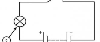
LED series connection diagram
LED series connection diagram
A break occurs when the connecting wire burns out due to a significant excess of the rated current.
But there is another reason. Due to manufacturing defects or overheating, the crystal structure is destroyed and breakdown occurs.
The most unpleasant situation is when the contact between the crystal and the connecting wire does not completely burn out, but is broken (temporarily disappears). In this case, the spotlight shines normally for 1-2 days, and then suddenly starts blinking like a strobe light.
Why do you need a driver for an LED and how to choose it
What will happen to the spotlight if only one LED breaks down? Here is a diagram of a 50-watt matrix connected to a 1.5A current source
In normal mode, all current is distributed evenly between all lines. Each LED carries a nominal current of 300mA.
In the event of a breakdown, only one LED actually shorts out.
Due to the reduced resistance, most of the current flows into the line with the broken element.
This instantly leads to burnout of the connecting wires. After which, the entire line is turned off.
Now a current higher than the nominal current begins to flow through the remaining LEDs - 375 mA. This will certainly cause overheating and another breakdown.
This means that another line will turn off.
And behind her is another one.
And another one. Until they all burn out.
How to replace the matrix on your TV yourself
But unlike this simulation, in reality, the last line does not burn out.
This is because the power supply has overvoltage protection.
The driver increases the voltage to produce a rated current of 1.5A. But due to abnormal LED resistance, the voltage rises above the permissible level.
The protection is triggered and the driver is disabled. Soon the voltage drops and it turns on again. This is where rhythmic blinking occurs.
To be fair, it must be said that these matrices belong to the first generation. Today there are already modified models with modernized drivers.
On them, when one line burns out, the current in the others does not change. True, their price is many times more expensive.
How to replace LEDs in a lamp if you don’t have a hair dryer or soldering station
Of course, not everyone has a soldering station for such repairs (I, for example, don’t have one at home). In this case, you can use a regular soldering iron for repairs, slightly modifying its tip. Just wind a copper winding wire with a diameter of 1-2 mm onto the tip, and sharpen and tin the ends of the wire. Why not a soldering station for repairing and replacing SMD parts?
All that remains is to replace the LED, and the repair can be completed. This can be done with a soldering iron with a thin tip or a regular one, but modified for desoldering. Before soldering, remove excess solder from the contact pads and apply flux to them. Now place the new LED in place, observing the polarity, hold it with thin tweezers and solder. Keep in mind that the soldered LED must be exactly the same type as the burnt one. Otherwise, such repairs will not last long.
Probable causes of failure and ways to eliminate them
Current limiting capacitor
So, first of all, you need to determine the cause of the malfunction of your device. If the spotlight turns on, but when turned on does not burn evenly, but flickers and blinks, the current-limiting capacitor C1 has probably failed. Many Chinese manufacturers make the mistake of using a current-limiting capacitor that does not match the parameters of the driver when trying to achieve maximum brightness from a not very powerful spotlight. A current-limiting capacitor at 400 volts rated operating voltage will do just fine.
power unit
Another common cause may be a failed power supply. There are two ways out of the situation - go to an electronics store, where they will help you choose a suitable power supply (its characteristics are indicated on it, therefore it is advisable to disassemble the spotlight and take the unit with you), or select a power supply (may be suitable from a scanner or printer).
The second option is possible, of course, only if you suddenly have unnecessary and non-working office equipment lying around that can serve as a power supply donor. Check the power supplies so that they are similar in parameters. An exact match is not necessary, but the parameters should not diverge too much. As mentioned earlier, if you have the skills to use tools and understand electronics, you can easily change the power supply yourself.
Driver
If a low-power spotlight needs repair, it is likely that it may not have its own power supply, and the function of changing currents in it is performed by the LED driver. Since the LED cannot be powered directly from the network, requiring an alternating current that differs from what the network can offer it, the spotlight uses a driver that takes into account the variation in the characteristics of the LED depending on the operating temperature and time, adjusting the output current supplied to the LED . It is this driver that can fail.
To replace it, you will need to disassemble the LED spotlight and find out the driver markings in order to buy or order a replacement. If you are a confident user of power tools, you can find a failed driver element and unsolder it and replace it. If you are repairing a DIY LED floodlight, most likely it will be quite easy for you to find the problem in the driver or find a similar driver and make a replacement. It will definitely be cheaper than buying or assembling a new spotlight from scratch.
Matrix burnout
Another option for failure of the design of your LED spotlight, in addition to a malfunction of the driver, power supply or other small elements involved in the current conversion process, may be the burnout of the LED matrix itself. If the LED itself fails, you need to find and purchase a diode with similar characteristics. After disassembling the spotlight, you will need to carefully uninstall the burnt matrix by unscrewing the four fastening screws and unsoldering the conductive elements. Then you will need to evenly and carefully apply a layer of thermal paste to the new diode, solder the current-carrying elements and carefully screw the matrix. It is necessary to take into account that the shape of the matrix must remain intact, that is, it is advisable to use the same screws that were originally used. They should not have conical heads, because if you use them, if you tighten them with a little more force, they can damage the matrix and all your work will be in vain.
Diagnostics
First of all, it is necessary to determine the cause of the LED spotlight malfunction. As an example, let's talk about checking the performance of a rectangular Volpe spotlight with a matrix including 9 diodes. The total power of the lamp is 10 W. The luminous flux is 750 lm.
The check is carried out in the following order:
- Inspect the wiring for physical integrity. Check for breaks, burnt insulation, or kinks in the cable. The purpose is to ensure that there are no breaks in the conductor.
- Check the device body, as well as the LED matrix for mechanical damage (deformation, chips, cracks).
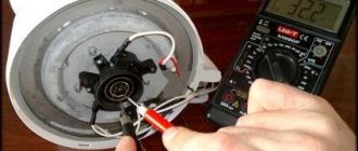
- The next task is to check the input voltage by opening the back panel of the case. The input voltage should be 220V (AC). If there is no voltage, the cause of the breakdown is not in the lamp, but in the electrical circuit. Measurements are carried out with a standard multimeter. The output voltage is 12 V (DC).
- If there is no output voltage, the breakdown is looked for on the converter board. Inspect the contacts for oxidation, look for cracks in the tin coating in areas of soldering or burnt-out elements.
- If the above verification methods do not produce results, test the performance of the matrix.
LED spotlight repair
To improve heat transfer, it is necessary to sand the two adjacent surfaces with P1500 grit sandpaper.
Then spread a thin layer of thermal paste. Excess paste will squeeze out on its own when heated or over time. The main thing is that there are no air bubbles inside.
Sergey ordered a 50 W LED on Aliexpress. It operates at 30-36V and consumes 1500mA during operation.
The luminous flux from it is 90-120 Lm/W. The color temperature of the light flux is 6000-6500 K, and the operating time is 100,000 hours. Good Chinese LED module.
When installing, the LED module can be slightly rubbed against the heatsink, because this makes it easier for excess thermal paste to come out.
When soldering an LED, remember that it is afraid of overheating, so solder quickly and accurately.
After repair, when assembling the protected LED spotlight, make sure that the rubber gaskets fit. Then the spotlight will work for a long time and reliably even for street lighting purposes.
Useful tips
Some useful tips for repairing LED floodlights:
- When replacing the matrix, be sure to pay attention to the polarity.
- Be sure to remove the hardened heat-conducting paste under the matrix.
- The surface should be degreased with alcohol.
- When soldering, you do not need to overheat the surface. Soldering time is up to 2 seconds. If the matrix is overheated, the crystals will be destroyed or their new characteristics will not allow the spotlight to function normally.
- To repair a high-power spotlight, the knowledge used in repairing low-power lamps is sufficient. There are no special differences between devices of different power.
- If a matrix with a large number of diodes is not filled with a compound solution, the non-working diode will need to be replaced. To perform this operation, a micro-soldering iron is required. You need to work carefully so as not to overheat the crystals.
- If it is impossible to see the values on the burnt-out resistances, you cannot do without the instructions for the spotlight. It must contain the relevant data.
Anyone can fix a spotlight. However, to perform repair work, at least basic knowledge of electrical engineering is required, as well as skills in using a soldering iron and a multimeter. You also need the ability to read diagrams to understand the design of the spotlight.
Checking the LED matrix
To check the operation of the matrix, it is recommended to use laboratory power supplies. In this case, it is necessary to supply less voltage than is required for the operation of this unit. After this, it will be necessary to measure the current indicators, that is, find out how much of it our device is currently consuming. If there are no malfunctions in this case, the matrix should light up. Upon completion of this procedure, it is necessary to gradually increase the voltage supplied to the matrix to nominal values. When the matrix flares up to full power, then we can assume that this piece of equipment is working. Many people involved in such work miss important points that are associated with the correct installation of various parts, which over time leads to breakdown.
Connection diagram of the LED matrix.
LED spotlight design and typical faults
An LED spotlight (LED) is a bright lighting device consisting of:
- LED emitting light;
- driver that controls the operation of the device;
- housings;
- a diffuser that increases the efficiency of the device;
- lenses that determine the shape, color and other parameters of the light flux.
The most common malfunctions in the spotlight are driver failure or LED burnout. The latter greatly lose brightness or burn out due to the fact that the thermal energy they generate is poorly removed into the atmosphere. This problem is typical for budget manufacturers who skimp on radiators.
Combustion or unstable operation of the driver is a problem typical for Chinese-made floodlights, in which manufacturers also save on literally everything. However, using these products can be beneficial if you know how to organize electronics. Chinese spotlights are very cheap and work well after the driver has been restored.
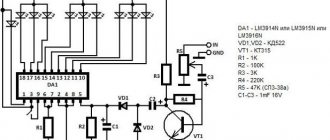
Electrical circuit of LED floodlight
The photo shows a typical electrical circuit of an LED spotlight driver. The operating principle of any spotlight driver circuit is the same.
Voltage from the household network is supplied to the driver input through fuse F1, filtered using LC elements and rectified by a diode bridge. Next it is smoothed out by electrolytic capacitor C13. A DC voltage of about 280 V is created at the capacitor terminals.
From capacitor C13, voltage is supplied through current-limiting resistors to zener diode D12 and pin 6 of the microcircuit. The zener diode provides power to the microcircuit with a voltage of 9 V, which is the reference for the operation of the driver as a whole. From capacitor C13, voltage is also supplied through the winding of transformer T1.1 to the output of field-effect transistor Q1 operating in switch mode.
The driver works as follows. From pin 5 of the microcircuit, high-frequency pulses are sent to the gate of transistor Q1, due to which the resistance between its drain and source becomes close to zero. At this moment, a current passes through the primary winding of the transformer, due to which voltage appears on the secondary winding. It is rectified by the high-speed diode SF28 and smoothed by the electrolytic capacitor SC1. The amount of current flowing through the LED matrix is determined by the resistance value of the resistors installed from pin 3 of the microcircuit to the common wire.
The most common ones that fail are electrolytic capacitors (they are easy to identify by their appearance - they are swollen), bridge rectifier diodes, a field-effect transistor, a high-frequency diode and a zener diode (if it breaks, the microcircuit fails).
The reason for the burnout of the LED matrix in the spotlight
Typically, LED matrices fail due to overheating. I decided to figure out why the LED matrix in this spotlight, despite the thick-walled duralumin body, which is also a radiator, burned out.
The first thing that caught my eye was that the matrix was secured with two screws, and not four, which is provided for by its design. The screw heads were conical, which could lead to deformation of the matrix substrate if the screws were tightened too tightly.
After unsoldering the current-carrying conductors and unscrewing the screws, the matrix was easily separated from the spotlight body. The photo shows the appearance. Recesses in the corners of the substrate instead of holes reduce the likelihood of it being evenly pressed against the radiator.
The reason for the burnout of the LED matrix became obvious after examining its reverse side. The area of the substrate opposite the burned-out area with LEDs was not covered with heat-conducting paste, although the paste on the body of the spotlight was applied evenly.
Typically, the section of the radiator to which the fuel element is pressed is ground. In the spotlight, this rule is doubly violated, since the area of the body to which the LED matrix is pressed is not polished, and is also painted with shagreen paint, which significantly reduces heat removal from the matrix.
Based on the above, we can conclude that the LED matrix failed due to overheating due to its poor pressing to the spotlight body during assembly.
Before installing the matrix into the spotlight body, the contact area was sanded with sandpaper until the aluminum and aluminum shined.
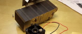
Cooling radiators
Most LED lighting fixtures come with cooling radiators. The presence of this element is a sign of the high quality of the device. In these products, a special seat is allocated, and a radiator is used to remove heat. The thermal paste needs to be replaced periodically. If this is not done, then over time the radiator will lose its efficiency and the board or unit will burn out. Disassemble the device and make sure that thermal paste is applied to both surfaces of the seat.
If necessary, apply a thin layer of special lubricant yourself to the entire surface of the seat. Too much thermal paste affects heat transfer just as negatively as its absence. To increase thermal output, you can screw an additional aluminum plate to the radiator, but make sure that it does not block the main air flow.
High-quality repair of LED light sources with your own hands is possible provided that safety rules are followed and the design diagram of the electrical device is available. The article described in detail the main causes and types of malfunctions, and provided recommendations for finding and eliminating them.
Recently, a friend asked me to help with a problem. He is developing LED lamps, selling them along the way. He has accumulated a number of lamps that are not working correctly. Outwardly, this is expressed as follows: when turned on, the lamp flashes for a short time (less than a second), goes out for a second, and so repeats endlessly. He gave me three such lamps to study, I solved the problem, the fault turned out to be very interesting (just in the style of Hercule Poirot) and I want to tell you about the way to find the fault.
The LED lamp looks like this:
Fig 1. Appearance of a disassembled LED lamp
The developer has used an interesting solution - the heat from the operating LEDs is taken by a heat pipe and transferred to a classic aluminum radiator. According to the author, this solution allows for the correct thermal conditions for LEDs, minimizing thermal degradation and ensuring the longest possible service life of the diodes. At the same time, the service life of the diode power driver increases, since the driver board is removed from the thermal circuit and the board temperature does not exceed 50 degrees Celsius.
This solution - to separate the functional zones of light emission, heat removal and power current generation - made it possible to obtain high performance characteristics of the lamp in terms of reliability, durability and maintainability. The disadvantage of such lamps, oddly enough, directly follows from its advantages - manufacturers do not need a durable lamp :). Does everyone remember the story about the conspiracy among incandescent lamp manufacturers about the maximum service life of 1000 hours?
Well, I can’t help but note the characteristic appearance of the product. My “state control” (wife) did not allow me to put these lamps in the chandelier where they are visible.
Let's return to the driver problems.
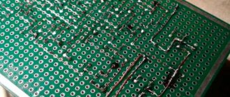
This is what the driver board looks like:
Fig 2. Appearance of the LED driver board from the surface mount side
And on the reverse side:
Fig 3. Appearance of the LED driver board from the power parts side
Studying it under a microscope made it possible to determine the type of control chip - it is MT7930. This is a flyback converter control chip (Fly Back), hung with various protections, like a Christmas tree with toys.
The MT7930 has built-in protection:
• from excess current of the key element • decrease in supply voltage • increase in supply voltage • short circuit in the load and load break. • from exceeding the temperature of the crystal
Declaration of protection against short circuit in the load for a current source is rather of a marketing nature