How can you produce electricity without batteries? With magnets of course! In this tutorial, I'll show you how you can use a magnet and some electrical components to make a simple flashlight that doesn't require batteries! This type of flashlight is great for hiking, camping, and emergency situations. Eliminating batteries means the eternal flashlight is always ready to go!
Required materials for a self-charging flashlight: a small piece of PVC pipe, magnetic wire, neodymium magnet, LEDs, 4 diodes or 1 diode bridge, capacitor, resistor, wire, breadboard and electrical tape.
Faraday flashlight - assembly
After we have decided what exactly the Faraday flashlight consists of, it is worth noting that it still has a power source, so it is not correct to think that the flashlight does not need a battery at all. In fact, it is discharged, so the light does not light.
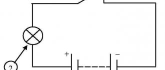
When we shake the flashlight, the magnet or battery will pass back and forth through the induction coil. An alternating current will appear, which, after passing through the diode rectifier bridge, will become smooth and constant.
Recharge the battery and the light will shine again. Conclusion: creating a flashlight from magnets and batteries is quite possible!
Each instruction for creating a flashlight will say that the body can be any object with an LED lamp or a cylinder-shaped part made of plastic.
Use your imagination, but don’t forget about the properties of the material you choose. In homemade projects, capacitors are often used instead of a battery.
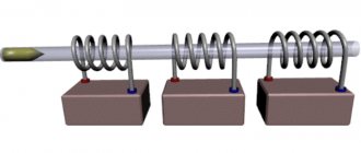
Following from the manufacturing diagram, the induction coil is formed by two windings with a length of forty millimeters (that is, each – twenty millimeters, conditionally).
On both sides, six hundred turns of copper wire of zero/eight millimeters in thickness are overlapped. The performance of the entire structure will depend on how the coil was wound.
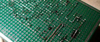
We carry out everything according to the markings, the first turns are strictly to each other, obligatory fixation with glue of the first row. And then the coils are located as neatly and close to each other as possible.
Remember that you need to install rubber magnet stops to ensure everything works properly.
These are the main tips for installing a flashlight with your own hands. Shake your device, if the light comes on, it means you did a great job! You will find the basic diagram, as well as photos of homemade lanterns, on the Internet.
Printing the case on a 3D printer
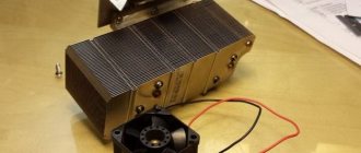
So, there was an idea, but it was difficult for it to materialize, since it was necessary to assemble a gearbox with an electric motor and stuff it into some kind of housing, and for most radio amateurs the housing is a “stumbling block.” But this task has been radically simplified with the purchase of an inexpensive 3D printer. Now the construction of any housing for a radio-electronic device is limited only by the author’s imagination.
The first pancake, as usual, was lumpy: I printed out the case, not yet knowing what the finished device would look like, taking the first engine I came across as a generator. It turned out that even with a very fast rotation of the handle, there was not enough voltage for stable operation of the flashlight. Then, taught by bitter experience, I approached the question more intelligently. I took a bunch of existing engines and tested them for suitability for this project.
We do this: we clamp the motor shaft into a screwdriver, give maximum speed and measure the voltage and short circuit current of the motor. Accordingly, we select the best copy. According to my observations, it is best to take a high-voltage (12 -24 volt) and low-revving motor.
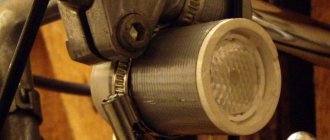
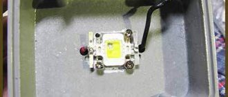
Further on the gearbox: I used factory gears, since my 3D modeling program does not have a library for constructing the latter and I am currently printing from PLA plastic, but it is not resistant to wear. The drive gear and motor were used from some kind of electric corrector for car headlights, the intermediate (large) one from the disc drive of the AIWA music center, the last one (on the motor) from a children's car. The lens was used from a non-working Chinese headlamp. On the plus side: it has a lens and the ability to change the focal length. The light source is a three-watt LED; it, of course, is not used “to its full potential,” but in terms of reliability it has no equal (with such a low load).
As you know, such flashlights have one more drawback - they shine while you turn the handle. To at least to some extent smooth out this drawback, I installed ionistors in the case with a total capacity of two farads. And in parallel with the latter, a five-volt zener diode, since the maximum voltage for these ionistors is 5.5 volts, and the generator is capable of delivering up to 12 volts without load. There is a switch installed in the side wall of the device that disconnects the LED from the ionistors; if not needed, you can turn it off and a charge will remain in the ionistor for later use. In the off position, when the knob is rotated, the process of charging the ionistors occurs.
Battery finger
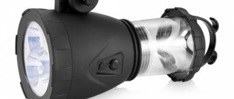
A certain community of foreign inventors managed to create a device, or flashlight, Lumen, based on the capabilities of a thermoelectric generator (TEG). It does not generate a powerful beam, but it shines no worse than pocket flashlights from Chinese consumer goods at any bazaar.
This technology, of course, is not applicable for a powerful “spotlight,” but for small pocket flashlights the circuit is simply ideal.
The principle of generating electricity with a mini-TEG in a Lumen flashlight is surprisingly simple. The generation supplies current to several LED “bulbs”. The glow is enough to read or write text in the dark.
The flashlight, weighing only 45 grams, is called a “finger” flashlight. It “turns on” at a temperature (warmth) of less than thirty degrees. It can also turn on at the appropriate air temperature.
The inventors installed a window on the device for your finger - touch it and light will appear. He can work like this without interruption indefinitely. The flashlight was announced for sale for $15. Look at the photo of the eternal flashlight, which never appeared on sale
This message was given by many sites back in 2015, as well as the promise of enthusiasts to begin producing flashlights in a year. In total, they lacked 5 thousand dollars for the final technological breakthrough. But according to the crowdfunding they announced (people's help), in just a couple of days such collections exceeded the amount by 328 percent. Where's the thermal flashlight? The Internet is silent.
Principle of operation
The device consists of several inductors that you can assemble yourself. The primary inductor actually serves as a power source or completely replaces its usual counterpart - the battery. Due to the movement of a rod of permanent magnets in it, an electric current is induced. Due to the oscillatory movements in the magnetic field, electric waves are created emanating from the coil at a certain frequency. A rectifier or diode bridge helps stabilize them and convert them into direct current. Without a storage capacity, such a device would have to be constantly shaken, so the next element in the circuit is a supercapacitor that can be recharged like a battery. Next, a step-up transformer or voltage converter is connected, which consists of a toroidal ferrite coil and two windings - base and collector. The number of turns can be the same, and is usually 20-50. The transformer has a middle connection point at opposite ends of both windings, and three outputs to the transistor. An autotransformer increases tiny current pulses into enough current to operate the LED, and a bipolar transistor is connected to control them. A similar electrical circuit has different names in different sources: joule thief, blocking generator, Faraday generator, etc.
Materials and tools
To create an “eternal flashlight” you will need copper wire (0.5 mm), PVC pipe (diameter 20 mm), a low-power reverse conduction transistor, a resistor, a diode bridge or a 2W1 rectifier and round neodymium magnets with dimensions of 15x3 mm. In addition, you need a 1F 5.5V ionistor (supercapacitor), a white 5V LED, a switch button, plywood and cotton wool. You will also need insulated copper wire and transparent glue.
Tools must include a soldering iron, a hacksaw, a file, sandpaper and a hot glue gun.