Radio-controlled toys can be seen in the hands of every child. Stores are overflowing with a variety of gadgets, and the most interesting thing today would be to assemble a radio-controlled car with your own hands.
In this instruction I want to show you how to make a radio-controlled car with your own hands. Instead of making a simple RC car, we'll be building a cardboard F1 racing car. Cardboard is publicly available and makes it possible for anyone to assemble such a machine right at home.
All materials for making the machine are easily accessible to everyone, and the article also contains links to purchase parts online.
Examples of devices [edit | edit code]
The principle of translational motion is implemented in a drawing device - a pantograph, the leading and driven arms of which always remain parallel, that is, they move forward.
In this case, any point on the moving parts makes specified movements in the plane, each around its instantaneous center of rotation with the same angular velocity for all moving points of the device. It is important that the leading and driven arms of the device, although moving in harmony, are two different
bodies. Therefore, the radii of curvature along which given points on the leading and driven arms move can be made unequal, and this is precisely the point of using a device that allows you to reproduce any curve on a plane on a scale determined by the ratio of the lengths of the arms.
In fact, the pantograph provides synchronous translational movement of a system of two bodies: the “reader” and the “writer”, the movement of each of which is illustrated in the above drawing.
Forward movement
- this is the mechanical movement of a rigid body, in which any straight segment rigidly connected to a moving body remains parallel to its original position.
One of the most important characteristics of the movement of a point is its trajectory, which in general is a spatial curve that can be represented in the form of conjugate arcs of different radii, each emanating from its own center, the position of which is different for different points of the body and can change over time.
In a particular case, a straight line can be considered as an arc, the radius of which under given conditions can be considered equal to infinity. And movement along an arbitrary trajectory is like a set of conjugate arcs.
In this case, it turns out that during translational motion, at each given moment in time, any point of the body rotates around its instantaneous center of rotation, and the length of the radius at a given moment is the same for all points of the body. The velocity vectors of the points of the body, as well as the accelerations they experience, are identical in magnitude and direction.
However, since the trajectory is a concept related to the field of kinematics and does not contain information about velocities, in the general case it does not give an idea either of the magnitude of the forces experienced by a material point or of their direction.
Nevertheless, there may be cases when, according to the conditions of the problem, it is sufficient to study the movement of one arbitrary material point of the body (for example, the movement of the center of mass of the body).
For example, an elevator car or a Ferris wheel car moves forward.
In the general case, translational motion occurs in three-dimensional space, but its main feature, the preservation of parallelism of any segment to itself, remains in force.
Mathematically, translational motion is equivalent to parallel translation.
When solving problems of theoretical mechanics, it is convenient to consider the motion of a rigid body as a superposition of the motion of the center of mass of the body and the rotational motion of the body itself around the center of mass (König’s theorem).
The force from the source to the executive body can be transmitted in a variety of ways. Versions of execution have become quite widespread, the purpose of which is to convert rotational motion into reciprocating motion. A similar mechanism is installed very often today. Let's consider the varieties, scope and many other points in more detail.
Classification of mechanical gears
Mechanical engineers have adopted several classifications depending on the classifying factor.
Based on the principle of operation, the following types of mechanical transmissions are distinguished:
- engagement;
- rolling friction;
- flexible links.
According to the direction of change in the speed, gearboxes (decrease) and multipliers (increase) are distinguished. Each of them changes the torque accordingly (in the opposite direction).
According to the number of consumers of transmitted rotational energy, the form can be:
- single-threaded;
- multi-threaded
Classification of mechanical gears
According to the number of transformation stages - single-stage and multi-stage.
Based on the transformation of types of motion, the following types of mechanical transmissions are distinguished:
- Rotational-translational. Worm, rack and screw.
- Rotational-swinging. Lever pairs.
- Translational-rotational. Cranks are widely used in internal combustion engines and steam engines.
To ensure movement along complex specified trajectories, systems of levers, cams and valves are used.
Electric drive
Single-speed asynchronous AC electric motors with a squirrel-cage rotor are most often used as electric drive motors. An asynchronous machine is connected to a three-phase network, so it must have three phase windings on the stator, creating a rotating magnetic field that drags the rotor along with it. The rotor rotates asynchronously, that is, at a speed different from the field speed. Possessing a rigid characteristic (dependence of torque on speed), these engines provide constant power over the entire speed range and a slight change in shaft speed under load.
The use of asynchronous electric motors with electric gear switching by changing the number of pole pairs greatly simplifies gearboxes. However, variable speed induction motors have constant torque at different speeds, which reduces their efficiency at low speeds.
A characteristic part of a large group of electrical machines is the collector - a hollow cylinder assembled from copper rings insulated from each other. The presence of a collector in AC machines allows the phases to be supplied to the rotor. Asynchronous electric motors with a wound rotor are used for mechanisms with smooth, step-by-step starting in difficult conditions during continuous operation.
The use of DC electric motors, the rotation speed of which can be adjusted within a fairly wide range (at constant power in a certain speed range) by changing the excitation field, turns out to be more preferable, since it significantly simplifies the gearbox.
In DC motors, the commutator provides a torque that is constant in direction. The scope of application of collector machines, especially DC machines, is quite extensive, and the presence of simple and small-sized rectifier devices allows them to be connected to AC networks. A particularly valuable property of a DC commutator machine is the ability to smoothly (steplessly) regulate the rotor speed.
An electric machine is called synchronous, the speed of rotation of the rotor of which is connected by a constant ratio with the frequency of the alternating current network into which this machine is connected. Synchronous electric motors are suitable in cases where a motor operating at a constant speed is required. Synchronous motors have slightly higher efficiency and lower weight per unit power than asynchronous motors designed for the same speed.
Electromagnets are often used to carry out auxiliary movements.
Application area
Rocker mechanisms are used in those devices and installations where it is necessary to convert rotation or swing into longitudinal movement or the reverse conversion.
They are most widely used in metalworking machines such as planers and slotters.
An important advantage of the rocker-lever mechanism is its ability to provide high speed movement in the reverse stroke. This makes it possible to significantly increase the overall productivity of the equipment and its energy efficiency, reducing the time spent on unproductive, idle movements of working bodies
A rocker mechanism with an adjustable slider length is also used here. This allows you to best adjust the kinematic scheme based on the length of the workpiece.
The conchoidal type mechanism is used in light wheeled vehicles driven by human foot muscle power - the so-called walker. The person operating the machine, imitating steps, alternately presses the pedals of the mechanism, fixed to the axle at one end. The rocker pair converts the rocking motion into rotation of the drive shaft, which is then transmitted by a chain or cardan drive to the drive wheel.
In analog computers, so-called sine and tangent rocker mechanisms were widely used. To visualize various functions, they use slider and two-stage circuits. Such mechanisms were also used in target tracking and weapons guidance systems. Their distinctive feature was exceptional reliability and resistance to adverse environmental influences (especially electromagnetic pulses) against the backdrop of sufficient accuracy to solve the assigned tasks. With the development of software and hardware of digital technology, the scope of application of mechanical analog computers has greatly decreased.
Another important area of application for rocker pairs is devices in which it is necessary to ensure equality of the angular velocities of the rockers while maintaining the angle between them. Couplings in which partial alignment of shafts is allowed, power systems for automobile engines, reverse devices on a steam engine.
Main types of axle shafts
Depending on the design, the axle shaft can be fully or partially unloaded from the bending moments acting on it.
Balanced axle shaft
more typical for heavy-duty vehicles, including buses. In the drawing, such an axle shaft will look like a part freely installed inside the bridge, and the wheel hub will rest on the bridge beam using two bearings. In this design, the axle shaft transmits exclusively torque, since the entire bending force is absorbed by the bearings.
Types of axle shafts
Half-loaded axle shaft
in the vast majority of cases it is installed on passenger cars and light trucks. The design of this type of axle shaft is different in that it has a bearing between the axle shaft itself and its casing, and the axle shaft is attached directly to the wheel hub. For this reason, bending moments periodically occur on the arm, which affect the axle shafts in the vertical and horizontal planes.
On front-wheel drive vehicles, axle shafts of a slightly different design are installed to transmit torque from the gearbox to the wheels. Such a drive shaft consists of an axle, internal and external CV joints.
Drive shaft design of a front-wheel drive vehicle.
Application area
Today, the ratchet as a part is used in the creation of various industrial units with components of engineering structures. At the same time, stable operation of various small elements of tools can be ensured. This point indicates the versatility of using ratchet mechanisms.
From a technical integration point of view, the device outperforms many other designs.
Very often, manufacturers use a ratchet as an element through which operating parameters are set. An example is fixing the cutting step in a certain range. In addition, installation is carried out during the direct manufacture of machine tools.
Recently, installation has been carried out in cylindrical grinding machines, the device provides radial feed. The mechanism is found in jacks and various winch systems, wind-up cars and other devices.
Types of mechanism
There are a wide variety of friction ratchet mechanisms available on the market. They can be used to implement a wide variety of tasks. Among the features of the classification, we note the following points:
- The profiled surface is often made in the form of a drum or rack.
- The rack-and-pinion version is extremely rare, since the functionality of the device is significantly reduced. Drum friction ratchets are much more common due to their compactness and other properties.
- The base profile is also classified according to a large number of characteristics. The most common are radial, rectangular and flat designs. Radial ones are widely used because they are compact and easy to install.
In most cases, the tooth has a classic shape, which ensures reliable operation.
https://youtube.com/watch?v=GMDe6caao-Q
Cardboard cake stand
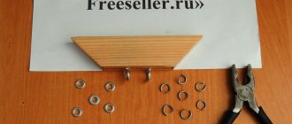
Cardboard, as a separate type of material, rather than a box, is also available for sale. To create a cardboard backing for a cake, we need to stock up on some materials and tools:
- one sheet of high-density cardboard - it is better to choose three-layer cardboard;
- self-adhesive paper or beautiful special packaging paper; a simple plastic bag.
Assortment of cardboard thickness
We will not cut out a cake shape from cardboard. We simply cover, for example, a square-shaped stand with wrapping paper, which we secure on the reverse side with pieces of tape.
We will assemble the cake on a base, only on baking paper cut to fit the circumference of the cake. And first, we will cover the substrate with additional polyethylene.
Simple kit for covering a cake base
It will turn out neatly and very convenient to carry and serve dessert.
Cake on a simple dessert base
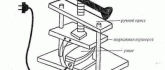
Toggle mechanism
The modern knee-lever mechanism is used in cases where a large force must be transferred to the executive body, but the driving force should not be large. In this case, hydraulics are often used as a drive, which largely determines the basic properties of the structure. The advantages include the following:
- High travel speed at idle. Due to this, it becomes possible to install the device in cases where it is necessary to ensure rapid movement of the moving element. An example is equipment designed for milling or turning, since it has a large number of moving units that must periodically change their position.
- Small linear dimensions of the working hydraulic cylinder. This property determines the possibility of creating a compact structure. Recently, compactness has been most valued, as equipment is becoming lighter and smaller. This simplifies installation and maintenance.
- Low indicator of the amount of working fluid in the system. Due to this, maintenance costs are significantly reduced. From time to time it is necessary to replenish the volume of liquid, since the operation of the structure leads to its consumption.
However, this embodiment has a fairly large number of disadvantages, among which we note:
- Quite a high cost of the drive and the need for periodic maintenance. That is why the device is installed in cases where it is necessary to transfer large forces. In the production of this type of lever mechanism, materials with high resistance to environmental influences are used.
- There is a possibility of damage to the line, which causes the leakage of working fluid and other problems. The design features of the design determine that there is a possibility of a variety of problems arising, for example, overshoot of the maximum position.
There are several varieties of the device in question, all of them are characterized by certain performance characteristics.
Homemade weather vanes of varying complexity: photo reports
When making a wind direction indicator with your own hands, many questions arise. The design is simple, but there are many options. For example, the swivel assembly can be made in different ways, not to mention the shape and size of the housing. Everyone chooses what they like best. To form at least a general idea of how you can make this useful device for a summer cottage or garden plot, we will give several examples of homemade weather vanes with step-by-step photos.
You can do something like this too
Based on a bearing from a VAZ pump
The bearing was taken from an old VAZ. Based on the size of the bearing, pipes were found - one of which this bearing fits into. We install a stopper in this pipe so that the bearing does not fall inside; after installing it, we weld it. From pipes of smaller diameter we make a cross, to which we will then attach letters indicating the direction of the cardinal points.
Making a weather vane with your own hands
We weld another piece of thin pipe to the top of the bearing. This will be the rotating part, to which the body of the weather vane will then be attached. We weld two short sections of pipe perpendicular to this pin - we will weld the cut weather vane to them. To protect the bearing from moisture and dust, we use a boot from the steering rod, pulling it before we started welding the rotating part.
We are gradually assembling the structure
A cat is cut out of an aluminum sheet 2 mm thick, the letters are made of galvanized steel. We'll spray paint them with bright red auto enamel, and the cat with black.
Components for a homemade weather vane
All that remains is to weld/attach all the parts to assemble the weather vane.
This is what everything looks like assembled
A homemade metal weather vane on a bearing is ready. Can be installed on the roof.
The simplest weather vane in 5 minutes from scrap materials
When hunting, fishing or dacha, you may need a wind direction indicator. You can make a very simple model literally from nothing. You will need:
- plastic or paper glass (preferably large capacity);
- thick wire (you can use aluminum or steel);
- plastic screed;
- a washer with an internal diameter not less than the diameter of the wire.
What you need The manufacturing process is very simple. First of all, carefully, without damaging the walls, remove the bottom. You can remove it from a paper cup, but you will have to cut it off from a plastic cup. Next, stepping back from the wider edge about a centimeter, we make two holes in the walls, located one opposite the other, and thread the wire. We bend one edge of the wire so that the wind indicator does not fall off.
We make a weather vane with our own hands from scrap materials
From the opposite side - from below - we put a washer on the wire, raise it to the level of the glass, leaving a very small gap (a few millimeters). We take the tie, tighten it, fixing the washer at the desired level.
Pointer at work
That's all, we made a simple weather vane with our own hands. Of course, it is very short-lived, but long-term service is not always necessary. And it will correctly indicate where the wind is blowing.
Electronic turning systems
Principle of operation
The operating principle of the rotating device is very simple and rests on two parts, one of which is mechanical and the other electronic. The mechanical part of the rotating device is respectively responsible for turning and tilting the battery. And the electronic part regulates the times and angles of inclination at which the mechanical part operates.
Electrical equipment used in conjunction with solar panels is charged from the batteries themselves, which in some way also saves money on powering the electronics.
Positive sides
If we talk about the advantages of electronic equipment for a rotary device, then it is worth noting convenience. The convenience lies in the fact that the electronic part of the device will automatically control the process of rotating the battery.
This advantage is not the only one, but is just another one in the list of those that were listed earlier. That is, in addition to saving money and increasing efficiency, electronics frees a person from the need to manually make turns.
How to make it yourself
It is not difficult to create a tracker for solar panels with your own hands, since the scheme for its creation is simple. In order to create a workable tracker circuit with your own hands, you need to have two photoresistors available. In addition to these components, you also need to purchase a motor device that will rotate the batteries.
This device is connected using an H-bridge. This connection method will allow you to convert a current of up to 500 mA with a voltage of 6 to 15 V. The assembly diagram will allow you not only to understand how a tracker for solar panels works, but also to create it yourself.
To configure the operation of the circuit, you must perform the following steps:
- Make sure there is power to the circuit.
- Connect the DC motor.
- Photocells need to be installed side by side to achieve the same amount of sunlight on them.
- It is necessary to unscrew two trimming resistors. This must be done counterclockwise.
- The supply of current to the circuit is started. The engine should turn on.
- We screw in one of the trimmers until it stops. Let's mark this position.
- Continue screwing in the element until the engine begins to rotate in the opposite direction. Let's mark this position as well.
- We divide the resulting space into equal sections and install a trimmer in the middle.
- We screw in another trimmer until the engine starts to twitch a little.
- We return the trimmer a little back and leave it in this position.
- To check the correct operation, you can cover sections of the solar battery and watch the circuit’s response.
Turning on redstone devices in 1st order, turning off in another.
Here, in pictures, it is described how to make such a mechanism.
There is nothing complicated in this mechanism, we just need: 1) Redstone 2) Repeaters 3) Any blocks 4) Devices affected by redstone 5) A little time
1. This is an already built mechanism, it looks like this:
3. Consider the thing that is applied to the mechanism above (front view) (you can do without this thing if you use a lever instead of a button (then you will have to wait for the signal from the lever to reach the end));
4. Piece (rear view);
PS If you want to use a long chain powered by a button, then with each extension by 1 device (I have pistons), place this thing 1 repeater further, and do a little magic with the repeaters. (with very long mechanisms there can be a lot of these things)
I hope everything is clear to you. The mechanism is not complicated, that’s why I didn’t make a video.
And further:
1) I came up with this mechanism myself, if you’re a fool, then prove it. 2) This is my first tutorial.
Now, happy building!
The article is taken from an open source. If you are against posting an article, contact the site administrator.
DIY reciprocating mechanism
You can save a lot by creating a reciprocating mechanism with your own hands. In some cases it is made from a drill, in others an electric motor is used to transmit the rotating torque.
We will name the following points as features:
- Most structures cannot be manufactured independently, since the required parts are characterized by high complexity. An example is the combination of a crank shaft and a gear.
- In all cases, calculations must be carried out, since otherwise it is impossible to provide the required parameters.
- It is possible to make a structure of the type in question only if you have special equipment. If the device is made on your own, then its actual parameters from the calculated ones may differ significantly.
In general, we can say that the task under consideration is quite difficult to perform. That is why the work should be carried out exclusively by professionals who can carry out complex calculations and also produce the required parts.
Causes of axle shaft failure
During the operation of the vehicle, the axle shaft constantly operates under quite serious loads, including:
- bending moment, which appears due to the effect of gravity on the car;
- tangential reaction that occurs when the vehicle starts to move and brakes;
- lateral force due to car skidding;
- lateral loads arising from the influence of strong cross winds.
Axle shafts experience almost extreme loads when the vehicle moves on dirt roads, as well as on broken highways.
A broken axle shaft leads to a complete or partial loss of vehicle control, so proper, thorough and timely care is of great importance.
During operation of the drive axle, it is necessary to periodically check the condition of the bearings located on the axle shafts. Their long-lasting performance can be achieved by providing complete protection against the penetration of dirt and liquids.
Advantages of cam mechanisms
The main advantage of the device is its ability to implement very complex spatial trajectories of movement of the pusher. In addition, the movement can be strictly controlled according to time phases depending on the rotation angle of the drive shaft. Moreover, its design is very simple to operate and maintain.
Another important advantage of the design over, say, electronic control systems with electric or hydraulic drive is its exceptional reliability
This is very important in those designs where it is necessary to achieve precise repeated repetition of the same movements, such as an engine or a sewing machine
DIY reciprocating mechanism
You can save a lot by creating a reciprocating mechanism with your own hands. In most cases, it is produced from a drill; in others, an electric motor is used to transmit rotating torque.
Let's name the following points as characteristics:
- Most designs cannot be made on our own, since the required parts are highly complex. An example is the combination of a crank shaft and a gear.
- In any situation, calculations must be made, since otherwise it is impossible to provide the required parameters.
- It is possible to make a structure of the type in question only if you have special equipment. If the device is made independently, then its actual parameters may differ significantly from the calculated ones.
In general, it must be stated that the problem under consideration is quite difficult to apply. That is why the work should be carried out exclusively by professionals who can carry out complex calculations and also make the required details.
How to calculate a simple lever mechanism yourself?
Before directly creating the mechanism, you should carry out calculations of the main indicators, as well as construct a load distribution scheme. The force calculation of the lever mechanism is carried out after determining the initial data:
- A kinematic diagram of mass and moments, inertia of links and the position of centers of mass is created.
- The law of motion of the mechanism is taken into account.
- External force loading is determined.
- The overlap angle of the lever mechanism is calculated.
The kinematic and force carried out involves the creation of a coordinate system that is used to calculate kinematic characteristics. The rocker-lever version is designed when creating a coordinate system and designating all the forces. The design requires a large number of different formulas, and verification must be performed at the end.
As a rule, the work in question is performed by engineers who take into account GOST design. This is due to the fact that the structural formula of flat levers is selected depending on their area of application.
Description of the invention for the patent
The invention relates to a group of mechanisms in which the connection of mechanical links is carried out by the passage of a magnetic flux in the absence of contact between them.
A mechanism is known that contains a drum rotating on an axis and a magnetic element.
The objective of the invention is to impart to the known mechanism the functions of converting reciprocating motion into reciprocating rotational motion and vice versa.
The technical result is achieved by the fact that in the mechanism for converting reciprocating motion into reciprocating rotational motion and vice versa, containing a drum rotating on the axis and a magnetic element, on the surface of the drum there is a closed screw channel with at least one ball enclosed in it, and the magnetic element is mounted on a rail with the ability to move along the drum; wherein the ball and the magnetic element have a magnetic connection. The magnetic element is balanced by a cylinder containing a lighter-than-air gas.
Figure 1 shows in a horizontal position the mechanism for converting reciprocating motion into reciprocating rotational motion and vice versa, side view; Figure 2 shows a cross-section of Figure 1 along A-A; in Fig. 3 the mechanism for converting reciprocating to reciprocating motion and vice versa is shown in a vertical position, side view; Figure 4 is a top view of Figure 3.
The mechanism for converting reciprocating motion into reciprocating rotational motion and vice versa contains a drum 2 rotating on axis 1, on the surface 3 of which a screw channel 4 is made, closed by a rigid thin-walled shell 5. The drum can be hollow or solid, located horizontally or vertically, and have the shape cylinder or truncated cone. The cross-section of the channel can be in the shape of a semicircle, square, rectangle, or triangle. Several balls 6 made of ferromagnetic material, for example, in the form of iron shot, are placed in the channel with the possibility of free rolling. At the side surface of the drum, a rack 7 is movably installed with a permanent magnetic element 8 attached to it, which can be moved along the drum. The drum, shell and rack are made of non-magnetic material. The balls (shot) and the magnetic element have a magnetic connection. In the case of a vertical drum arrangement, the magnetic element can be balanced by a cylinder 9, for example, in the form of a thin-walled rigid ball containing a gas (hydrogen helium) lighter than air. The ball can be attached to a magnetic element or a rail.
When the axis 1 is turned, the balls 6 begin to roll along the screw channel 4, made on the surface 3 of the drum 2; forcing, due to the influence of a constant magnetic field, the magnetic element 8 and the rack 7 to move in the direction of movement of the balls. The thin-walled shell 5, tightly covering the surface of the drum, prevents the balls from falling out of the channel. Thus, in the proposed mechanism, the reciprocating rotational motion of the drum is converted into the reciprocating motion of the rack.
When the rack with a magnetic element moves along the drum, a constant magnetic field acts on the balls located in the screw channel, causing them to move in the direction of movement of the magnetic element and rotate the drum. Thus, the reciprocating motion of the rack is converted into the reciprocating rotational motion of the drum.
With a vertical arrangement of the mechanism for converting reciprocating motion into reciprocating rotational motion and vice versa, the cylinder 9, filled with a lighter-than-air gas, balances the force of gravity from the masses of the magnetic element and the rack.
The proposed mechanism can be used in the educational process, technical creativity, and in the manufacture of instruments and toys.
Information sources
1. Polytechnic dictionary. Ch. ed. I.I. Artobolevsky. – M.: Soviet Encyclopedia, 1976. – P.268-269.
Tools
Having assessed the volume and types of work, I collected tools in accordance with the following list:
- a jigsaw, which I use to cut circles from fiberboard and chipboard;
- I will need an electric drill to drill holes for connecting furniture parts;
- screwdriver for fastening screws;
- an air compressor with a gun for blowing holes and treated surfaces;
- hammer;
- iron;
- wrench;
- improvised tools (pliers, screwdriver, metal ruler, tape measure, knife, pencil).
Required set of tools
Disadvantages of cam mechanisms
The most noticeable disadvantage is the complexity and high cost of producing mechanism parts. The most labor-intensive part is the production of the control profile. The technological process begins with the casting of a workpiece from high-strength steel alloys, which are particularly resistant to variable mechanical stress, abrasion and temperature changes. Next, high-precision machining is required, followed by grinding and polishing of the surfaces. Hardening of the working surface is achieved by heat treatment and carburization. Such camshafts or oil pump drive cams are expensive, but they can last hundreds of thousands of kilometers.
Another disadvantage is the small load that the pusher can push. This occurs due to the high friction in the mating pair, in addition, significant lateral loads arise on the rod. This drawback limits the power capabilities of the device's executive body.
To combat this drawback, a roller pusher is used, placed on a ball or needle bearing. For large engines with large valve diameters and powerful return springs, a rocker arm design is used. The different lengths of the rocker arms work like a lever system, transforming more travel on one arm into more force on the other.
Passive office chair adjustment
Passive settings are achieved without additional mechanisms. This type of adjustment includes adjustment of the armrests. Some models adjust the position of the armrests horizontally or in height.
You can also seal the seat and back to ensure a comfortable fit, evenly distributing the load on the chair. Another mode is a sharp bend at the top edge of the chair. Neutralizes compression of the lower extremities in the area of the patella.
It is advisable to adjust the armrest so that the curvature of the elbows is at least 90°.
Functional purpose and device
View of the screw-nut cavity profile: a) arched contour b) radius contour
The purpose of the mechanism in question is to convert the rotational movement of the drive into linear movement of the working object. The transmission consists of two components: a lead screw and a nut.
The screw is made of high-strength steel grades 8ХФ, 8ХФВД, ХВГ, subjected to induction hardening, or 20Х3МВФ with nitriding. The thread is made in the form of a spiral groove with a semicircular or triangular cross-section. Depending on the operating conditions of the screw, the cavity profile can have several designs. The most commonly used is an arched or radius contour.
The female part, the nut, is a composite unit. It has a complex structure. Usually it is a housing in which there are two liners with the same grooves as those of the lead screw. Material of insert parts: volumetric hardening steel grade KhVG, cemented steels 12KhN3A, 12Kh2N4A, 18KhGT. The inserts are installed in such a way as to ensure preload in the screw-nut system after assembly.
Inside the helical grooves there are hardened steel balls made of ShKh15 steel, which circulate along a closed path during transmission operation. For this purpose, inside the nut body there are several bypass channels made in the form of tubes connecting the turns of the nut. Their length can be different, that is, the balls can return through one, two turns, or at the end of the nut. The most common is return to an adjacent turn (DIN system).
Static balancing of the crank-slider mechanism
During the movement of mechanism links with changing speeds (accelerated movement), inertial forces and moments arise in them. They are called dynamic loads. Such loads lead to vibrations; vibrating parts radiate their vibrations into the air, causing airborne noise.
Dynamic loads also lead to repeated deformations of parts, increased wear, accumulation of material fatigue and premature failure.
Noise and vibration also have a negative impact on people and machinery located near the source. And finally, energy is wasted to excite vibrations and emit noise, which reduces the efficiency of the crank-slider mechanism.
The causes of vibration are divided into:
- power, vibrations are disturbed by the periodic application of forces to an object;
- kinematic, disturbance occurs due to the movement of parts;
- parametric, excitation occurs due to forces and moments of inertia.
Vibration activity is divided into
- Internal, arising and spreading within the physical boundaries of the crank-slider mechanism. It affects only its parts and spreads little outside.
- External. It acts on the supports of the mechanism, its connections with other parts of the overall structure, the transmission, and so on. The main reason that causes such vibration activity is the imbalance of levers and links.
To eliminate the causes of vibration, static balancing of the crank-slider mechanism is carried out. The mechanism must be in equilibrium at rest, and the friction forces are assumed to be zero.
To do this, calculate the masses of all links and construct a graph of the forces acting on them at rest, primarily the forces of gravity. The masses of the links must be balanced taking into account the length of the arms (distance from the center of rotation).
During static balancing, the masses of the links are assumed to be concentrated at the geometric center of the link.
If the general center of mass of the system undergoes accelerated motion, the mechanism is considered unbalanced. The goal of the procedure is to achieve zero acceleration of the center of mass. To do this, balancing masses are added to the moving parts, reducing the acceleration to zero.
After static balancing, the stage of dynamic balancing of the crank-slider mechanism begins. In this case, calculations are carried out taking into account the actual spatial configuration of the parts.
During the production of a real product, additional imbalances of links arise due to material defects, casting errors, machining and assembly. To eliminate them, balancing the crank-slider mechanism is used. It consists in:
- determining the location of imbalance using vibration diagnostics tools;
- movement and securing of balancing weights provided for by the design of the product;
- drilling, sampling or surfacing of the required masses of material in calculated locations;
- repeated vibration diagnostics.
The cycle of operations is repeated until the moving parts are satisfactorily balanced.
MX series. Rotating mechanisms with additional support for large diameter rotating worktops
The mechanism is mounted on a square support platform:
The large support area allows you to install a round tabletop of large diameter on the mechanism - from 1 to 1.6 meters.
The round tabletop (the future rotating circle) is attached to the mechanism with self-tapping screws. Before attaching the table top, you must remove the mechanism ring from the support platform, attach the ring to the table top, then screw the platform back to the mechanism. All that remains is to turn the rotating center over and place it on the table.
After use, the spinning center can be easily removed from the table and stored away.
If you need advice on where to buy a round tabletop, write. Tabletops are offered by various suppliers in Russia; round tabletops are available in a variety of decors and colors.
The load on the MX mechanism is up to 50 kg.
Recommendations for mounting MX mechanisms when assembling a large diameter rotating table center
Prices for MX rotation mechanisms:
| MX-50. Mechanism with a square support for installing a rotating tabletop with a diameter of 100 cm. Height 2.8 cm. Product weight 3.4 kg. | 3000 | 2 days. | Order |
| MX-60. Mechanism with a square support for installing a rotating tabletop with a diameter of 120 cm. Height 2.2 cm. Product weight 3.2 kg. | 3300 | 2 days | |
| MX-70. Mechanism with a square support for installing a rotating tabletop with a diameter of 140 cm. Height 2.2 cm. Product weight 4 kg. | 3600 | 2 days | |
| MX-80. Mechanism with a square support for installing a rotating tabletop with a diameter of 160 cm. Height 2.2 cm. Product weight 5 kg. | 3900 | 2 days |
Need some advice? We will answer your questions
How to order. Payment. Delivery. Guarantee
Complete the mechanism with a round tabletop of the diameter you need. Read more about round tabletops
Clock turning mechanism
The design of the clock mechanism is basically quite simple. In order to create such an operating principle, you need to take any mechanical watch and connect it to a solar battery motor.
In order to make the engine work, it is necessary to install one moving contact on the long hand of a mechanical watch. The second fixed one is fixed at twelve o'clock. Thus, every hour when the long hand passes through twelve hours, the contacts will close and the motor will turn the panel.
The time period of one hour was chosen based on the fact that during this time the sun passes through the sky about 15 degrees. You can establish another fixed contact for six hours. Thus, the turn will take place every half hour.