May 02, 2017
LED cubes will never lose their popularity and attractiveness. There are a huge number of projects for 5x5 and smaller cubes on the Internet. Today we will build a cube of 8x8x8 diodes.
Building a cube is quite challenging for beginners and enthusiasts. Therefore, we tried to simplify this process as much as possible and create instructions that will be extremely detailed and complete, since any minor error can be critical, and it will be quite difficult to eliminate it.
To work on the project, it is enough to have basic soldering skills, have basic knowledge of electronics and be familiar with the operation of Arduino boards.
Led cube - what you need for self-assembly
If you are into DIY projects or like to tinker with electronic circuits, try assembling an LED cube with your own hands. First you need to decide on the sizes. Once you understand how the device works, you can upgrade the circuit with either more LEDs or fewer LEDs.
Let's look at how this works using the example of a cube with a side of 8 LEDs. This cube can be intimidating for beginners, but if you are careful when studying the materials, you will easily master it.
To assemble the led cube 8x8x8 you will need:
Operating principle of the circuit
Small 5mm type LEDs draw a negligible current of 20mA, but you are going to be lighting quite a lot of them. A 12V and 2A power supply is perfect for this.
You will not be able to connect all 512 LEDs individually because you are unlikely to find a microcontroller (MK) with so many pins. Most often, there are models in cases with a number of legs from 8 to 64. Naturally, you can find options with a large number of legs.
How to connect so many LEDs? Elementary! A shift register is a chip that can convert information from parallel to serial and vice versa - from serial to parallel. By converting serial to parallel, you will get 8 or more signal pins from one signal pin, depending on the register capacity.
Below is a diagram illustrating the working principle of a shift register.
When you supply a bit value, namely zero or one, to the serial Data input, it is transmitted along the edge of the Clock clock signal to parallel output number 0 (do not forget that in digital electronics the numbering starts from zero).
If at the first moment of time there was one, and then within three clock pulses you set the input to zero potential, as a result of this you will get the input state “0001”. You can see this in the diagram on lines Q0-Q3 - these are four bits of parallel output.
How to apply this knowledge in building an LED cube? The fact is that you can use a not quite ordinary shift register, but a specialized driver for LED screens - STP16CPS05MTR. It works on the same principle.
The most interesting part: demo videos + my work
Standard animations (+video)
Analysis of the musical spectrum (+ video)
The implementation of this feature was somehow not particularly impressive, I expected more.
Key “0”
— switches the cube to this mode.
Key “1”
- returns the cube to standard animation playback
Animated display of readings from the DHT22 temperature and humidity sensor (+ video)
I am not so much attracted by the possibility of creating some new abstract animations as by displaying some really useful information on a cube.
For example, from the DHT22 temperature and humidity sensor. But at the same time, I agree that a static display is not very interesting, so I still implemented a simple animation - this is the flight of letters and numbers from the back wall of the cube to the front. The code declares three arrays of unsigned char
:
massBukov[56]
, containing the letters M, Y, S, K, U, B, T
massNumber[40]
, containing the numbers from 0 to 9
massBUF[64]
, a buffer array sent to cube
Since the resolution of one side of the cube is 8x8, we can display on it a maximum of a two-digit number, which will be formed depending on the sensor readings. A letter corresponding to the type of reading will appear before the numeric readings, for example "B"
is for humidity and
"T"
is for temperature. When starting the program, I implemented the display of the name of a familiar resource on which this review was posted. After this, the temperature and humidity per cubic meter are displayed cyclically. To successfully compile this sketch, the DHT library is required.
Sketch for displaying temperature and humidity on a cube
// Output temperature and humidity from the DHT22 sensor // 5V power supply, the signal pin of the sensor is connected to pin 2 of the Arduino and is pulled through a 10K resistor to 5V #include “DHT.h” #define DELAYS 150 #define LAYER 8 #define COLUMN_COUNT 64 DHT dht (2, DHT22); // Output #2 for the sensor void printMass(unsigned char *massP); void printNum(unsigned char number); void printMain(void); unsigned char des, ed, h, t; unsigned char massBUF[64]; unsigned char massBukov[56] = { 0xFF, 0xFF, 0x30, 0x1C, 0x1C, 0x30, 0xFF, 0xFF, // M 0xF0, 0xF8, 0x1C, 0x0F, 0x0F, 0x1C, 0xF8, 0xF0, // Y 0x4C, 0xDE, 0x9B, 0x99, 0x99, 0xD9, 0x7B, 0x32, // S 0x00, 0x81, 0xC3, 0x66, 0x3C, 0x18, 0xFF, 0xFF, // K 0xFC, 0xFE, 0x07, 0x03, 0x03, 0x07, 0xFE ,0xFC, // U 0x00, 0x00, 0x2C, 0x7E, 0x52, 0x7E, 0x7E, 0x00, // B 0x00, 0x60, 0x60, 0x7E, 0x7E, 0x60, 0x60, 0x00 // T }; unsigned char massNumber[40] = { 0x00, 0x7C, 0x44, 0x7C, // 0 // 0 0x00, 0x00, 0x7C, 0x00, // 1 // 4 0x00, 0x74, 0x54, 0x5C, // 2 // 8 0x00, 0x7C, 0x54, 0x54, // 3 // 12 0x00, 0x7C, 0x10, 0x70, // 4 // 16 0x00, 0x5C, 0x54, 0x74, // 5 // 20 0x00, 0x5C, 0x54, 0x7C, // 6 // 24 0x00, 0x7C, 0x40, 0x40, // 7 // 28 0x00, 0x7C, 0x54, 0x7C, // 8 // 32 0x00, 0x7C, 0x54, 0x74 // 9 // 36 }; void setup(void) { dht.begin(); _delay_ms(DELAYS); Serial.begin(38400); Serial.write(0xAD); //command for cube to work from Arduino printMass(massBukov,COLUMN_COUNT,LAYER); printMass(massBukov+8,COLUMN_COUNT,LAYER); printMass(massBukov+16,COLUMN_COUNT,LAYER); printMass(massBukov+24,COLUMN_COUNT,LAYER); printMass(massBukov+32,COLUMN_COUNT,LAYER); } void loop(void) { h = dht.readHumidity(); t = dht.readTemperature(); printNum(h); _delay_ms(500); printMass(massBukov+48,COLUMN_COUNT,LAYER); _delay_ms(600); printNum(t); _delay_ms(600); printMass(massBukov+40,COLUMN_COUNT,LAYER); _delay_ms(600); } void printMass(unsigned char *massP, int razmer, int sdv){ for(int z=0 ; z<8 ; z++) massBUF[z] = massP[z]; for(int y=0; y<8; y++){ printMain(); for (int i=razmer-1 ; i>=0 ; i—){ massBUF = i<4; i++){ massBUF[4+i] = massNumber[des*4+i];//tens massBUF = massNumber[ed*4+i]; //units } printMass(massBUF,COLUMN_COUNT,LAYER); _delay_ms(DELAYS); }
[MENU]
How to connect LEDs?
Of course, using a driver will not completely solve the problems associated with connecting a large number of LEDs. To connect 512 LEDs, you will need 32 such drivers, and even more control legs from the microcontroller.
So we'll go the other way and combine the LEDs into rows and columns, so we get a two-dimensional matrix. The ice cube occupies all three axes. Having finalized the idea of combining an 8x8x8 LED cube in which the LEDs are combined into groups, we can come to the following conclusion:
Combine layers of LEDs (floors) into circuits with a common anode (cathode), and columns into circuits with a common cathode (or anode, if cathodes were combined on floors).
To control such a design you need 8 x 8 = 16 control pins per columns, and one for each floor, there are also 8 floors in total. In total, you need 24 control channels.
The input block receives a signal from three pins of the microcontroller.
To light the required LED, for example, located on the first floor, the third in the first row, you need to apply a minus to column number 3, and a plus to floor number 1. This is true if you have assembled floors with a common anode, and the columns - a cathode. If it is the other way around, the control voltages must be inverted accordingly.
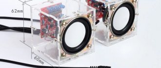
Hardware: housing
I designed the housing for the cube myself, deciding to keep it as simple as possible.
The size turned out to be 67mm3. This is a single part that can be 3D printed. The boards are fixed into it due to the elongated edges. For printing, I decided to use Shapeways' multijet fusion (MJF) process. It turned out nice, although the dimensional accuracy was lower than expected. At first, the panels fit into the frame too loosely, which I easily corrected with a small amount of superglue, which I applied to its ribs and left to dry overnight.
3D printed frame (1)
3D printed frame (2)
Practical recommendations for successful assembly
In order to make it convenient for you to solder a cube of LEDs, you need:
For the cube of LEDs to work correctly, you need to assemble it in layers with a common cathode, and the columns with an anode. Connect to the Arduino pins what is indicated in the diagram as input in the following sequence:
| Arduino pin no. | Chain name |
| 2 | L.E. |
| 3 | SDI |
| 5 | CLK |
DIY New Year's glowing snowman, step by step with photos
A glowing snowman can be made not only from duralight, but also in another equally interesting way, using disposable cups:
- Buy 300 white disposable plastic cups:
- Take 25 cups and fasten them in a circle using a heat gun or stapler:
- Place the cups in a checkerboard pattern on top of the first row in 7 rows, fastening them not only from the bottom and sides, but also from above to each other so that the structure is strong:
Make another such structure, place LED garlands inside each one, and then fasten them together with a stapler. Decorate the snowman so that it has buttons and a nose. You can use any stationery for this and more:
We create the magic of the holiday ourselves, so don’t expect pleasant surprises from someone, create them yourself with pleasure! Let our tips and recommendations help you out in everyday life, helping you make your holiday unforgettable!
What if I don’t have such skills?
If you are not confident in your abilities and knowledge of electronics, but want such a decoration for your desktop, you can buy a ready-made cube. For those who like to make simple electronic crafts, there are excellent simpler options with 4x4x4 edges.
Cube with face size 4 diodes
Ready-made kits for assembly can be purchased in stores with radio components, as well as a huge selection on Aliexpress.
Assembling such a cube will develop the novice radio amateur's soldering skills, accuracy, correctness and quality of connections. Skills in working with microcontrollers will be useful for further projects, and with the help of Arduino you can learn to program simple toys, as well as automation tools for everyday life and production.
Unfortunately, due to the peculiarities of the Arduino programming language - sketch, there are some limitations in terms of performance, but believe me, when you hit the ceiling of the capabilities of this platform, most likely mastering the work with “pure” MKs will not cause you any significant difficulties.
Source
Alternatives to 8x8x8
I will briefly comment on the alternative options available for purchase. There are several modifications of cubes to choose from, with support for memory cards, with speakers for playing music, however, among the more expensive versions, modification number 4 is of interest, which can
3D8S
program using a USB-TTL converter - this modification may be of interest for those who don't know how to program.
Other features like memory cards, speakers, spectrum analysis, remote controls - personally, in my opinion, it’s just an overpayment of money for unnecessary features. If you know how to program, then I recommend taking the cheapest version with Arduino support, number 2
. On Ali the cost is cheaper than on ebay. In addition, there are several types of each modification - three-color (as in the review), and one-color, i.e. All LEDs are the same color, and there are only five of these colors available: red, white, blue, green and pink. I just don’t understand why the pink version is the most expensive of them.
1)
The simplest and cheapest version of the cube, without Arduino support
EBAY: Three-color -
$20 + $2.5 (shipping) ||
Single color -
18.30-21.30$ + 2.5$ (delivery)
AliExpress: Three-color -
17.48$ ||
Single color -
$16.28-18.68
2)
With support for work from Arduino
EBAY: Three-color -
21$ + 2.5$ (delivery) ||
One-color —
19$ + 2.5$ (shipping)
AliExpress: Three-color —
18.67$ ||
Single color -
$17.71-20
3)
Arduino support + remote control + music spectrum
EBAY: Three-color -
$24.23 + $2.5 (shipping) ||
Single color -
$23-27 + $2.5 (shipping)
AliExpress: Three-color -
$25.78 ||
Single color –
$25.28-27.38
4)
Arduino support + remote control + music spectrum + work directly with a PC via the 3D8S program
EBAY: Three-color -
$28 + $2.5 (shipping) ||
Single color -
$27-30 + $2.5 (shipping)
AliExpress: Three-color -
$27.39 ||
Single color -
$26-29
5)
Music spectrum + work directly with a PC via the 3D8S program + memory card slot
EBAY: Three-color -
$35.83 + $2.5 (shipping) ||
Single color -
$35.68-38 + $2.5 (shipping)
AliExpress: Three-color -
$29.34 ||
Single color -
$28.5-30
6)
Remote control + music spectrum + work directly with a PC via the 3D8S program + memory card slot + speaker for playing music
EBAY: Three-color -
$30 + $2.5 (shipping) ||
Single color -
29-30$ + 2.5$ (delivery)
AliExpress: Three-color -
36$ ||
Single color -
$35-36
Creating a large LED cube
LED cubes will never lose their popularity and attractiveness. There are a huge number of projects for 5x5 and smaller cubes on the Internet. Today we will build a cube of 8x8x8 diodes.
Building a cube is quite challenging for beginners and enthusiasts. Therefore, we tried to simplify this process as much as possible and create instructions that will be extremely detailed and complete, since any minor error can be critical, and it will be quite difficult to eliminate it.
To work on the project, it is enough to have basic soldering skills, have basic knowledge of electronics and be familiar with the operation of Arduino boards.
LED Location
I would like to immediately note that you should not choose large LEDs, as they will block each other and the distant rows will be difficult to see. Also, do not use very bright diodes. So that the light of each diode is point-like.
For the project we will use not very bright 3mm diffuse LEDs with long legs.
For a better view of each LED, we will use very thin connecting wires.
The LEDs will be connected to each other using their legs. Cathodes with cathodes, anodes with anodes. For our cube we will need 8 such matrices.
Electronic circuit
Creating eight layers of 64 diodes each takes a lot of time, but it is quite simple to do.
The most difficult moment is building a circuit to control the LED cube and finding faults in the circuit, if of course there are any.
The MAX7219 chip will be used to control our cube. It was originally designed to control 7-segment LED displays. Using this chip, we will reduce the number of controls on each layer to a minimum.
To control each layer of 64 diodes you will need:
To create a cube we will need 8 sets of the above components. It's also worth noting that you may need a different resistor for the specific LEDs you'll be using. Its role in this circuit is to limit the maximum voltage that the MAX7219 chip will produce.
To make assembly easier, the cube was divided into two parts. 4 layers on each of them.
The cube can be controlled externally by any microcontroller via the SPI interface. For this project we will be using the popular Arduino (Nano) board. To control our cube using only 3 signal wires (SPI) and 2 power wires (5V DC). You can use the more common Arduino Uno board instead of the Nano. They are very similar (except for size), so there shouldn't be any connection problems.
It is also worth paying attention to the fact that all components should be soldered to the bottom of the printed circuit board.
Jumpers are used to connect the boards together. To connect two boards you need 5 jumpers. To create one block of 4 layers of LEDs you will need 15 jumpers.
Most cubes are solid, unlike ours. And if any LED in the middle of the cube fails, it is quite difficult to get to it. In our case this will not be difficult.
Package
The entire set was initially tightly wrapped in several layers of foam - everything is fine with that. Having put aside the walls of the acrylic case, in the bag with the other components I saw an enclosed piece of paper with a link to instructions for assembling the cube.
Contents
1)
Acrylic case - 6 walls
2)
Main motherboard made of fiberglass
3)
Fiberglass 8-pin racks
4)
3 bags of LEDs (256 red, 128 blue and green)
5)
Microcontroller STC 15F2K60S2
6)
USB power cable 3.5mm (Nokia)
7)
Speaker cable 3.5mm (male-male)
Bag with radio components
9)
Bag with screws and nuts for the acrylic case
10)
Remote control
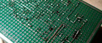
The motherboard is made of fiberglass and I must say, it is dense and strong, it does not bend with your hands, it feels like good quality. There are 64 through holes drilled in it - this is not easy, since it is this board that will play the role of a stencil when soldering the LED group, so you no longer have to saw and drill your stencil, which is a plus:
If you place it on the top wall of the acrylic wall, then it will lie almost flush with the grooves into which other acrylic walls are inserted:
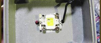
Three bags of LEDs, with identification circles of the corresponding color. There are as many red LEDs as there are green and blue ones combined, i.e. 256pcs. red and 128 each - blue and green. However, in reality there should be more of them, because both buyers and sellers understand that some of them may be defective or the user will damage some during soldering, so it is a sign of politeness and good form to add extra LEDs on top:
The size of one of these is 3mm
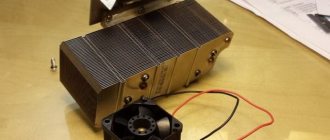
Microcontroller STC 15F2K60S2, 40-pin, in DIP package. He alone will control the entire process, although in other cube assembly kits there are usually several shift register chips in addition
Four posts, fiberglass, 8-pin, 4 pins on each flat side. It also feels like it’s made with high quality:
Two cables, one USB, to connect power to the cube, has a 3.5mm round plug, which was previously used in old Nokia phones. Second 3.5mm audio cable to connect the sound source to the cube:
The cube's remote control is normal, there is an infrared transmitter at the top end, no batteries included, which is a minus:
The acrylic walls are covered with adhesive kraft paper on top. There are grooves along the edges, and protruding parts that are inserted into these grooves. There are also holes for screws and motherboard connectors. This case is expensive, the seller says that cheaper versions of these cases from other sellers will not fit his cube, and obviously he brags about this, not being embarrassed by such a high price tag.
Eight pairs of screws and nuts to secure the walls of the acrylic case
[MENU]
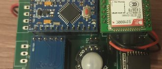
Contents of the bag with radio components
1)
Infrared receiver in a shielding casing
2)
Four multi-colored LEDs
3)
Various connectors:
- Two identical round 3.5 mm audio connectors - Round connector for power connection - UART connector 3S1P for receiving commands from Arduino 4)
64 collet contacts for LED grid
5)
10 kOhm resistor
[MENU]
Checking the cube
It is better to check the cube before complete assembly, each layer separately. This will make it easier to fix problems if there are any, of course.
To test, we connect each layer in turn to the Arduino Nano board (you should install the test program in advance). The lines should light up alternately from top to bottom.
You need to download the code to your board and then connect it to the finished cube.
That's all. All that remains is to enjoy the resulting device.
Source
Putting it all together
First, we prepare the case - make a small hole on the side or in the lid for 4 wires, which we will connect to the positives. We also mark the grid in the lid and drill small holes for the minuses of the bottom row of the cube. When everything is ready, insert the cathode legs into the prepared holes and secure the cube to the lid. You can do this using the same legs, but it is better to use additional fasteners, and you can move on to the next step - attaching the microcontroller to the cube.
Minus
If we look at the cover from the inside, we will see a square of 16 points with 4x4 sides located at the cathode exit points. For greater clarity, let's mark this grid as a chessboard, where the lower left corner is A1, next in row B1, and vertically A2 and in a similar sequence right up to the upper right corner, which logically turns out to be G4.
After marking, we begin to connect the controller contacts with the negative outputs according to the following scheme - A1 to contact TX1, B1 to D5, B1 - D9, G1 - D13. The next row is A2 on RX0, B2 - D4, B2 - D8, G2 - D12. Third row - A3 to A5, B3 - D3, B3 - D7, G3 - D11. The last one - A4 grids are connected to A4 of the controller, B4 - D2, B4 to D6 and G4 to D10.
Plus
After we are done with the minus, we move on to the plus. To begin with, let’s select the mounting points on the cube - turn it to a vertical position (the body is at the bottom) and take note of the vertical edge closest to the large (for 4 wires) hole. The solder points will be on the four horizontal layers between the fin diodes and the first diode to the side (right or left doesn't matter).
Now, we solder 4 pieces of wire to these points, and through resistors we connect them to the following contacts of the microcontroller - the top layer to A0, the second from the top to A1, the third to A2 and the bottom to A3.
The last step is to install the power supply: connect the plus batteries to the toggle switch, and then to the UIN contact; Solder the minus to the GND pin. We hide the filling in the case, turn it on and enjoy the play of light...
However, if you don't have time to make your own, you can always purchase a cube from the Lighthouse store!
LED cube 3x3x3 on Arduino Uno
You can find quite a few videos on youtube.com that show various colorful LED cubes blinking beautifully and controlled using Arduino. But access to the manufacturing technology and software code of these devices is offered for money. In our article, we will look at creating the simplest similar flashing LED cube 3x3x3 with the simplest blinking algorithm (easier for beginners), on the basis of which you can then program your own samples (patterns) of blinking (switching) of the LEDs of this cube. Moreover, all this will be absolutely free for you - our site does not require any money for reading the information posted on it (unless you intend to distribute it later somewhere - in this case it will be a violation of copyright. Active links on the Internet to articles on allowed on our website).
As shown in the above figure, the 3*3*3 LED cube consists of 27 LEDs arranged in rows and columns to form a cube shape.
Many similar cubes can be designed. The simplest of them will be a 3x3x3 cube. To design a 4*4*4 cube you will already need 64 LEDs. That is, with an increase in the linear dimension of the cube, the complexity of its manufacture increases many times over.
The 3x3x3 LED cube is the easiest to manufacture, not only because it contains quite a few LEDs, but also due to the following conditions:
In most cases, regular LEDs consume 2 to 5 mA of current. Therefore, if we use LEDs that consume 2 mA, then we can control 9 such LEDs without problems from one Arduino Uno pin, since the Arduino Uno pins are capable of providing a current of 20-30 mA.
White LEDs were used in this project, but you can use LEDs of any color - with colored LEDs the cube will look even more impressive.
To control this cube, we need 12 pins of the Arduino Uno board.
Features worth knowing about
Solder
plays an important role here. At my request, a friend once brought me a roll of solder strip. And everything would be fine, but it was when soldering the fiberglass racks to the motherboard that I became convinced of how crappy and disgusting this solder is. They will not be able to properly solder closely spaced contacts, since instead of four contacts, two or even one are formed. And even if with a thin tip it was possible to solder the contacts without obvious snot, then the matter will not be limited to this, since when connecting adjacent contacts there will still be short spots due to microscopic snot, which can be examined under a microscope. Due to bad solder, I had to resolder the contacts on the stands five times, but at the same time I was convinced of how well these stands and the motherboard were made, otherwise the tracks on them would have fallen off long ago. Bad solder usually has a matte surface after soldering, but good solder shines after soldering and no obvious snot is formed.
Flux
Throughout the entire process of building the cube, I used KIngbo 218 flux. LEDs are afraid of overheating, but thanks to the flux, touching their leads with a heated tip was about half a second. The flux was applied with a syringe with a thin needle, which saved it. As a result, I used about 1.5 cubes of flux for everything. Since the work ahead is extensive, it is better to do soldering with a hood like mine.
Sting and temperature
The T12-BCM3 “hoof” type tip was mainly used to form LED grids and solder radio components to the motherboard. To solder fiberglass racks I used a T12-D16 tip. The heating temperature always remained 320 degrees.
The order of LED groups by color
It is not at all necessary to follow the seller’s idea and solder the LEDs exactly this way (Fig. 1), when each color represents a horizontal layer. You can do it differently when, for example, the front panel consists entirely of red LEDs, and the back panel is green, with blue remaining in the middle (Fig. 2):
Power and current measurements
As mentioned above, there are two ways to power the cube with current - through the round connector on its left side and through the 4-pin connector on the front side.
Rated voltage 5V. Of course, I measured the current consumption. It is clear that if we are dealing with animation, then the current consumption will fluctuate. With the bottom backlight turned on (4 multi-colored LEDs), the current consumption range was 50-80mA
:
With the bottom light turned off, this range was significantly reduced to 25-47mA
I would say this is a small power consumption, so this cube can easily be powered from a smartphone with OTG support via a USB-OTG cable:
[MENU]
Required Components
Arduino Uno board, 220 Ohm resistor (3 pcs.), 5 V power supply.
Breadboard, connecting wires, 27 LEDs.
Soldering iron, solder and flux (rosin).
SR2032 battery, some tools.
An empty cardboard box, a pencil, a ruler and several jumpers (connectors).
Construction of a 3x3x3 LED cube
Step 1.
First, you need to use an SR2032 battery or a multimeter to check the LEDs for serviceability, because if it later turns out that some LED is faulty, then replacing it in an already assembled cube will not be very easy.
Step 2.
Then it is necessary to remove the insulation from the connecting wires as shown in the figure. You can use any jumper wires to create the cube, but it's worth noting that breadboard wires will work just fine for this purpose. Then the resulting bare wires must be cut into pieces 7 cm long - a total of 6 such pieces are needed. These pieces of wire will be used to bond the layers of LEDs together.
Step 3.
In this step, you need to take an empty cardboard box and stick white paper on its top as shown in the picture. White paper will be needed for precise positioning of the points.
After that, take a pencil and a ruler and mark 9 points on the paper every 2 cm thus forming a cube structure as shown in the picture.
We use a distance of 2 cm here because the length of the negative contacts of the LEDs is 2.5 cm. That is, in this case we will have 5 mm for soldering one LED to another. If we choose a larger distance, then soldering may become a problem; with a smaller distance, the cube will look somewhat awkward. Therefore, 2 cm will be the most suitable distance in this case.
After this, take any pointed object, such as a pen or pencil, and make a hole at each point. The holes should be of such a size that they hold the LED firmly enough - they should not be too small (the LED will not fit into them or we will not be able to wiggle it while soldering) or too large (the LED will fall into them). Therefore, check each hole made using an LED.
Step 4.
After that, place one LED in the hole and bend its positive terminal as shown in the picture below.
After this, bend the positive terminal of the LED again so that it forms an 'L' shape. If you look closely at the LED pin, you can see a small indentation where it should be bent into an 'L' shape. After this, bend the negative terminal of the LED to the right as shown in the following figure.
Step 5.
Then repeat all these steps for the remaining two LEDs and arrange these 3 LEDs in a row shape as shown in the picture. This template will be used for all the other LEDs in the cube. You can even bend the leads of all 27 cube LEDs first, and only then arrange them and solder their ends.
But first, let's repeat the described procedure for 9 LEDs, which we will arrange in the form of a matrix as shown in the figure.
Step 6.
After this, solder all the negative terminals of the LEDs as shown in the figure. Three LEDs will form a row.
After that, take two bare conductors 7 cm long (we prepared them earlier), place them as shown in the picture and solder 6 ends of these LEDs to form a complete matrix.
Now all the negative pins of the 9 LEDs are connected to each other, that is, we will have 9 positive pins (CP1-CP9) and one negative pin (CN1). After we take this structure out of the holes in the cardboard and cut off the protruding ends we will get one layer of our LED cube as shown in the following picture.
Step 7
We must take a similar sequence of actions to make the other two layers of the cube, the appearance of these constructed two layers is shown in the following figure.
Step 8
Now that we have all 3 layers of the cube, we need to join them together to create a cube.
After this, we attach the remaining 3rd layer to the resulting structure and we will have a complete cube. Soldering the 3rd layer will be a little more difficult than soldering the 2nd to the first, so try to do it carefully so as not to break the structure.
When soldering this entire structure, keep in mind that you should not heat (touch) the lead of the LED with a soldering iron for more than 5 seconds, otherwise you can overheat the LED and it will fail - and replacing it in an already made (at least partially) cube structure will not be easy.
Review navigation
1. Packaging
- Contents of the bag with radio components
2. Assembly.
Sequence - Step 1: Preparing the LEDs - Step 2: Soldering the LEDs - Step 3: Motherboard - Step 4: Soldering the fiberglass 8-pin racks - Step 5: Soldering the LED grids to the rack - What a fully assembled cube looks like - Dimensions and weight of a fully assembled cube cube
3. How to create and display your own figures.
Working with arrays. Connecting to Arduino - A little introduction to arrays - Why the char data type?
— Why is an array needed with 64 elements? — Synchronization of Arduino and Cube. The procedure for transferring arrays to the cube - Drawing your own graphics and converting them into an array of characters 4. ✪ The most interesting part: demo videos + my work
- Standard animations (+ video) - Analysis of the musical spectrum (+ video) - Animated output of sensor readings to the cube temperature and humidity DHT22 (+ video)
5. Features you need to know about
- Solder - Flux - Tip and temperature - Order of LED groups by color - Power supply and current measurements
6. Conclusions and thoughts.
Pros and cons - Advantages - Disadvantages
7. Alternatives to 8x8x8 8. Links to additional materials
[MENU]
Program source code
In the resulting cube, if we want to turn on one LED, for example, the LED in the second column of the first layer, we will need to power the CP2 pin and apply ground to the CN1 pin. According to the connections made in the circuit, we need to apply a high level voltage to PIN3 of the Arduino (which is connected to CP2) and a low level voltage to PIN A0 (which is connected to CN1).
We can light any other LED in the same way. Further in the program, in an endless loop, we will light all the LEDs in our cube one by one.
void setup() for (int i=0;i pinMode(i,OUTPUT); // pins S0-10 are set to data output mode > pinMode(A0,OUTPUT); //PIN A0 is set to data output pinMode(A1, OUTPUT); // PIN A1 is set to data output pinMode(A2,OUTPUT); // PIN A2 is set to data output
digitalWrite(A0,HIGH); //apply logical “1” to A0 pin digitalWrite(A1,HIGH); // apply logical “1” to A1 pin digitalWrite(A2,HIGH); // apply logic "1" to A2 pin /* add setup code here, setup code runs once when the processor starts */ > void loop() digitalWrite(A0,LOW); // ground is applied to layer 1 of the cube for (int i=2;i digitalWrite(i,HIGH); // turn on each LED in layer 1 one by one delay(200); delay(200); delay(200); digitalWrite(i ,LOW); > digitalWrite(A0,HIGH); // logical “1” is applied to layer 1 of the cube
digitalWrite(A1,LOW); // ground is applied to layer 2 of the cube for (int i=2;i digitalWrite(i,HIGH); // turn on each LED in layer 2 one by one delay(200); delay(200); delay(200); digitalWrite(i ,LOW); > digitalWrite(A1,HIGH); // logical “1” is applied to layer 2 of the cube
digitalWrite(A2,LOW); // ground is applied to layer 3 of the cube for (int i=2;i digitalWrite(i,HIGH); // turn on each LED in layer 3 one by one delay(200); delay(200); delay(200); digitalWrite(i ,LOW); > digitalWrite(A2,HIGH); // logical “1” is applied to layer 3 of the cube >
LED cube 4x4x4
I present a project of a 3D LED Cube with a 4x4x4 matrix.
64 LEDs form a cube with sides 4x4x4, which is controlled by an Atmel Atmega16 microcontroller. Each LED has its own virtual address and can be controlled individually from a microcontroller, thus allowing you to achieve amazing effects.
See the video of the cube in action below:
Step 1. What do we need?
The first thing is the patience to solder all 64 LEDs together