10.09.2021
The circuit diagram for this acoustic switch was found on one of the bourgeois sites. After checking, it became clear that the circuit was not working, after some experiments and alteration of the circuit - lo and behold! she earned it! Almost all the values of the components used were changed to make the circuit more accessible to beginner radio amateurs, and this is the end result.
Perhaps this is the simplest circuit that can exist; it uses a minimum number of components that are available to everyone. As a result of the alteration, domestic parts were used, which greatly facilitates the selection. The microphone was taken from a Chinese tape recorder; you can also use domestic ones, such as pine.
The microphone amplifier is assembled on two KT315 transistors, but to increase the sensitivity of the microphone it is advisable to use transistors like KT368 or its imported analogues; in general, transistors are not critical.
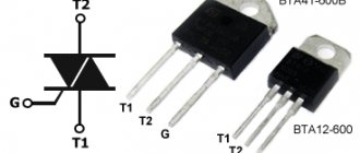
The power part of the circuit is a powerful bipolar transistor that controls the load, and in order to control large loads a relay was used (12-24 or 220 volts).
The signal from the microphone is amplified and sent to the base of a powerful key, the transition opens and it is at this moment that the relay is triggered, the microphone reacts to loud sounds (for example, clap), the sensitivity of such a circuit is 4-5 meters. At the second clap, the circuit is automatically switched off, therefore, the supply of current to the load is stopped.
The capacitors are electrolytic, the voltage is not so important, you can use the appropriate capacitors with a voltage of 10, 16, 25, 50 volts.
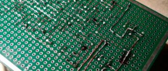
The range of supply voltages is also quite wide - from 3.5 to 14 - 16 volts, the current consumption in idle mode (when the circuit is turned off) is practically zero. The circuit can be assembled either on a breadboard or by surface mounting; the values of the parts are not critical and may deviate in one direction or another by 20%, but try not to replace the capacitances of the capacitors used, since the best parameters are obtained with the capacitors indicated on the diagram.
List of radioelements
| Designation | Type | Denomination | Quantity | Note | Shop | My notepad |
| Bipolar transistor | KT315A | 2 | To notepad | |||
| Bipolar transistor | KT818A | 1 | To notepad | |||
| Rectifier diode | 1N4007 | 1 | To notepad | |||
| Electrolytic capacitor | 1 µF | 2 | 10-50V | To notepad | ||
| Resistor | 10 kOhm | 2 | To notepad | |||
| Resistor | 3 MOhm | 1 | To notepad | |||
| Resistor | 48 kOhm | 1 | To notepad | |||
| Resistor | 1.8 kOhm | 1 | To notepad | |||
| Resistor |
set NS048
Based on this acoustic relay, you can independently create security systems, as well as other devices that can respond to sound, for example: automatic sound lighting switches, systems that track the source of sound and, of course, “smart” toys.
Specifications
Supply voltage [V] 9-12
Maximum current consumption [mA] 60
Description of the operation of the acoustic relay
The appearance of the acoustic relay and its electrical circuit are shown in Fig. 1
and
Fig.
2. Fig. 1.
Appearance of the acoustic relay
The electrical circuit consists of two main parts: analog and digital. The analog part includes two operational amplifiers A1 and A2, the digital part includes inverters N1...N4.
From the output of the electret microphone, an electrical audio signal is supplied to the input of the first operational amplifier A1, which matches the microphone with the output stage assembled on the operational amplifier A2. The sensitivity of the circuit as a whole is set by trimming resistor P1. The gain of the output stage is determined by the ratio of resistances R7, P1 and R5.
The amplified audio frequency signal is fed to the driver circuit. As it passes through inverter N1, capacitor C2 is charged to a logical one voltage at the lower input of inverter N2 in the circuit. As soon as the capacitor is charged, the output N2 changes the logical level to the opposite one, thereby forcing the trigger circuit built on the N3N4 inverters to switch to the opposite state. A logical one appears at the output of inverter N4, opening transistor TR1. As a result of this, LED D2 lights up and the winding of the electromagnetic relay K1 is connected to the power source, which switches the load through contacts K 1.1. Diode D1 is necessary to protect the transistor during its switching from current surges resulting from transient processes in the electromagnetic relay winding.
If the electret microphone does not pick up acoustic vibrations for some time, the variable component at the output of operational amplifier A2 will be zero, which leads to the appearance of a logical zero at the output of inverter N1. Capacitor C2 begins to discharge through resistor R1. After the discharge process is terminated, driver N2 resets the trigger circuit to its original state, which leads to the closure of transistor TR1, and consequently, de-energization of the electromagnetic relay winding. The load is switched off. The acoustic relay goes into standby mode.
Acoustic relay assembly
Before assembling the acoustic relay, carefully read the recommendations for installing electronic circuits given at the beginning of this book. This will help avoid damage to the printed circuit board and individual circuit elements. The list of set elements is given in Table. 1.
Table 1.
List of elements of the NS048 set
| Characteristic | Title and/or note | ||
| Brown, green, red* | |||
| R2, R9, Rll, R12 | Yellow, purple, red* | ||
| Brown, grey, orange* | |||
| Brown, black, orange* | |||
| Brown, black, brown* | |||
| Red red, red* | |||
| Orange, white, brown* | |||
| Trimmer resistor | |||
| 100 µF, 16/25 V | Capacitor | ||
| 10 µF, 16/63 V | Capacitor | ||
| Capacitor (22p - marking) | |||
| Capacitor (104 - marking) | |||
| Capacitor (56 - marking) | |||
| Red LED | |||
| Transistor. Replacement BC548 NPN | |||
| 7400 or 74LS00 | Chip | ||
| LF353 or TL082 | Chip | ||
| Electret microphone | |||
| Printed circuit board | |||
| Sockets for microcircuits | |||
| Relay 6V/2A | |||
| Battery connector | |||
| Pin contacts | |||
| * Color coding on resistors. | |||
Form the element leads, install them on the board and solder the leads. Connect the power supply and load according to the diagram shown in Fig. 3.
Rice. 3.
Connection diagram of the power supply and load to the acoustic relay board
Turn on the power to the acoustic relay electronic circuit. Use resistor P1 to set the required sensitivity of the device. Now everything is ready for successful operation of the acoustic relay.
In the event that you want to make a structurally complete device based on the NS048 kit, you can select a suitable stabilized power supply and housing for the acoustic relay in the catalog given in this book or on the website www.masterkit.ru. The design of the board provides for its installation in the case: for this there are mounting holes along the edges of the board for 03 mm screws. A correctly assembled device does not require additional configuration for operation.
Even a novice radio amateur can assemble such an acoustic relay. The NS048 kit is already fully equipped with everything you need, so all that remains is to install the components. Problems that arise during assembly can be discussed at the conference at https://www.masterkit.ru, and questions can be asked at:
NS048 sets, as well as other sets from the MASTER KIT catalog, can be purchased in radio parts stores or at radio markets.
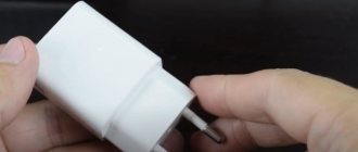
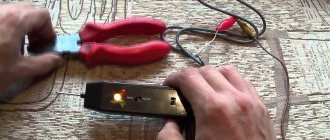
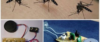
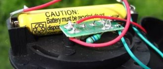
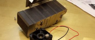
Hello everyone, today we are going to talk about the acoustic switch, and although there are many IC circuit diagrams for this on the Internet for beginners, sometimes it is difficult to find the ICs. With transistors this is already easier and simpler, I saw the diagram - it is surprisingly simple: a two-stage signal amplifier from a microphone on a KT315 or take the modern transistors indicated in the diagram. For example 2sc945 with high gain. You can also replace the power bd140 with the domestic KT818. At first I used 2 pieces of bc547, but later, after testing the circuit with bd140, it turned out that it had burned out, then I replaced it with kt818 and everything worked. The acoustic relay is powered by a 15 V battery. Microphone, taken from a Nokia headset. Transistors bc547 and kt818, load - lamp from garlands, resistors are looking for exactly at nominal value. Capacitors are not a problem. I collected everything on cardboard for the experiment.
The light bulb is designed for 6 volts, so it didn’t last long and burned out after two pops. But it is clear that it works...
Let's take a look at the diagram. The photo shows the parts we need.
We draw conclusions after the tests - pros and cons.
pros
: the circuit is simple and does not require configuration, scarce parts are not used, simplicity of the circuit, large power range.
Minuses
: the relay reacts to any loud sounds, especially low frequencies. Low sensitivity, unstable operation at sub-zero temperatures, you need two claps, and sometimes three.
As you can see, there were more disadvantages than positive aspects; on the other hand, the design showed itself to be very good, with its simplicity. Good luck to all beginners in their endeavors and good work of electronic devices!
Acoustic switch made easy | DIY master class
A couple of weeks ago, an LED panel for room lighting was assembled and it was decided to assemble an acoustic switch for it, and today I want to look at perhaps the simplest acoustic switch circuit.
The scheme was found on one of the bourgeois sites and slightly altered. The device allows you to turn the power circuit on and off with a clap. I intend to use it to turn on the lights. The device is quite sensitive thanks to a double amplifier using low-power transistors. It responds to clap at a distance of 5 meters from the microphone. All parts were replaced with domestic ones.
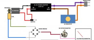
The microphone amplifier uses domestic transistors of the KT 315 series with any letter or index. The final stage uses a powerful transistor switch based on a bipolar transistor of the KT 818 series, all other details are the same as in the original circuit. You can exclude the relay from the circuit and connect a load in its place, but this is only in cases where you need to control loads with power up to 12 volts; if you need to control loads with power from the network, you can’t do without a relay. At the moment of clap, the microphone receives the wave, and as a signal it is sent to a power amplifier, which alternately amplify the signal received from the microphone. The amplified signal arrives at the base of the switch, its magnitude is sufficient to trigger the transistor, and at this moment the junction of the transistor opens and conducts a current that powers the connected load or relay.
When assembling, observe all the ratings of the parts; even a slight slope can lead to abnormal operation of the switch. The device responds not only to pops, but also to low-frequency noise (powerful bass, etc.).
The supply voltage range is from 4 to 16 volts, power only from stabilized DC voltage sources and under no circumstances use switching power supplies, the device will not work with them!
For the trial version, the device was mounted mounted, then it will be transferred to the board, the main thing is that everything works without failures.
sdelaysam-svoimirukami.ru
Application
The light switch claps on and off in response to the noise it makes. The operating algorithm is as follows: the first clap is switching on, the second is switching off.
It is recommended to install devices of this type only in quiet rooms. Premises of this type include bedrooms, storage rooms, utility rooms, and basements. It is irrational to install cotton devices in rooms where there are many people (offices, living rooms, industrial areas), since extraneous noise leads to false reactions of the devices.
The most common place to install a slam light switch is in the bedroom. It is very convenient to control the lighting without getting out of bed. Cotton systems are popular in families with small children, since to turn the light on or off you no longer need to reach for a high-mounted switch.
Many people confuse cotton and acoustic devices. The acoustic switch is triggered by any noise, and the clap switch is triggered only by claps.
SIMPLE ACOUSTIC RELAY
| radioskot.ru An acoustic switch is a very useful and necessary thing in the household, especially if you want to automate some devices or lighting in your home and add creativity to your home! Using an acoustic switch, you can turn the lighting off and on or use it for other devices, such as an electric kettle or fan. This scheme is fully operational, streamlined and stable. There are many diagrams of similar devices on the Internet, but when assembling them, a lot of performance problems arise and some of them lead to long discussions at the end of which, the problem is often not solved. Below is the diagram itself. The circuit is powered by a voltage of 5 to 9 volts, so choosing a power source will not be difficult. You can use, for example, a crown or other batteries and accumulators. If you need stationary power, then there are many power supply circuits online, even a transformerless one will do. The printed circuit board is made for DIP components, but despite this, it has quite compact dimensions and choosing a housing for it will not be difficult. You can download the printed circuit board from the link: akusticheskiy_vyklyuchatel.zip (downloads: 463) List of parts for assemblyPCB manufacturingI will not explain in detail how to make a printed circuit board, as it will take a lot of time. The PCB file is opened using the sprint-layout 6.0 program: sprint-layout-6.zip (downloads: 394) The circuit uses diode VD1; it is needed to protect transistor VT3 from the EMF of the relay coil. If you connect a relay as a load, then you need to install a diode; if you use a light load, then you can install a jumper instead. After making the board, to avoid oxidation, tin the thresholds with tin. Open the sprint-layout 6.0 program and solder all the parts on it according to the location. If everything is done correctly, the parts and values are not mixed up, then the device should work immediately without any problems. This is what the assembled acoustic switch looks like. And one more photo with a connected battery and an LED on the load. I would like to tell you about one problem that may arise. The circuit contains a 1.5 kOhm resistor R8, if you use an LED as a load, you can leave it, if you plan to install a relay, then replace the resistor with a 2 Ohm. There shouldn't be any more problems)) The result was an inexpensive but very effective and useful device that will definitely find its use in the household!)) Source usamodelkina.ru |
Specifications
As an example, let’s look at the characteristics of a standard device for turning the light on and off by clapping.
Device data:
- Power is supplied from a standard network with a voltage of 220 Volts.
- The maximum total power of consumers does not exceed 300 Watts.
- Sound control ranges from 30 to 150 decibels.
- Permissible temperature range: from 20 degrees below zero to 40 degrees above zero.
- Housing protection class - IP30.
A variety of lamps are used in the network:
- Incandescent and halogen light sources.
- Energy-saving or fluorescent light bulbs.
- LED devices.
The specified characteristics comply with the requirements of the law of the Russian Federation number 261. This act regulates the rules for the rational use of electrical energy.
The equipment is similar in size to a matchbox, that is, compact. This makes it possible to install it close to the lamps. The device is fixed using self-tapping screws or double-sided tape.
DIY cotton switch: diagram, video, photo
To increase comfort and simplify everyday routine, people are constantly improving devices and inventing new ones. Today we’ll look at a device for controlling electrical appliances remotely using sound. A homemade cotton machine is useful, for example, for turning on the light in a vestibule or pantry, where for some reason finding the switch in the dark is difficult or inconvenient. Below, for the readers of https://samelectrik.ru, we will tell you in detail how to make a cotton switch with your own hands, what elements need to be prepared and according to what scheme to carry out the assembly.
Assembly diagrams
All cotton or acoustic machines are united by the presence in the circuit of a microphone, which is needed to record sound. The design also provides a trigger or time relay to control the power relay.
In this circuit, operating from a 220V network, the signal from the electret microphone is supplied to transistor VT1 for amplification, then to the resistance matching unit, the emitter follower on transistor VT2. Next, a trigger and a signal comparator are assembled on the TM2 digital chip.
A comparator is necessary to protect the switch from acoustic interference; it cuts off sounds that are too short or long. The signal that has passed through changes the state of the trigger (on or off), and the trigger, in turn, controls the load—an incandescent lamp—through a power transistor and thyristor.
A circuit for assembling a homemade cotton switch with a similar purpose is based on an integrated timer.
To make it easier to study the diagram, we have identified zones on it. A microphone amplifier on a KT3102 transistor, a comparator on a 555 chip, a TM561 trigger and a KT3102 transistor, which controls the power relay.
No less interesting would be the self-assembly of an acoustic relay on an Arduino microcontroller:
To make a cotton machine with your own hands, you need to prepare three boards:
- Arduino Nano;
- sound module;
- power relay board.
You also need a PC, a USB cable, and a 5 Volt power supply. You need to install the Arduino IDE program on your PC to flash the microcontroller firmware.
By copying the text of the sketch (program) and pasting it into the Arduino IDE window, you can immediately flash the controller. By changing some adjustment parameters and rewriting the device, you can fine-tune a homemade sound relay for yourself. As we can see from the diagram, the controller has four wires: two for power, yellow is the wire that goes to control the power relay from pin 13. Green is the control wire from the microphone, connected to the analog input A0 of the controller.
The chip contains 8 analog inputs and 14 digital input/output contacts. For our project, we took A0 and D13, since together with it the LED on the Arduino board lights up.
Arduino sketch for making a sound relay: Sketch
By changing the value of if(analogRead, we set the sensitivity threshold, the maximum value that can be set is 1024. By making changes to the delay line, the execution time of the sketch changes. This sets the readiness time for switching. In addition, a protective threshold is set against interference and false positives. In addition, The microphone sensitivity can be adjusted with a variable control on the board.
To configure and test the circuits, we took an Arduino UNO simulation board. After receiving positive results and testing the program, an article was written.
The video below clearly shows a homemade cotton switch, which we assembled according to the diagram provided:
Video instructions
Several simple ideas for making your own acoustic light switch are shown in the video:
Now you know how to make a cotton switch with your own hands. We hope that the provided assembly options, simple diagrams and video tutorials were useful and interesting for you!
Also read:
samelectrik.ru
Hello everyone, today we are going to talk about the acoustic switch, and although there are many IC circuit diagrams for this on the Internet for beginners, sometimes it is difficult to find the ICs. With transistors this is already easier and simpler, I saw the diagram - it is surprisingly simple: a two-stage signal amplifier from a microphone on a KT315 or take the modern transistors indicated in the diagram. For example 2sc945 with high gain. You can also replace the power bd140 with the domestic KT818. At first I used 2 pieces of bc547, but later, after testing the circuit with bd140, it turned out that it had burned out, then I replaced it with kt818 and everything worked. The acoustic relay is powered by a 15 V battery. Microphone, taken from a Nokia headset. Transistors bc547 and kt818, load - lamp from garlands, resistors are looking for exactly at nominal value. Capacitors are not a problem. I collected everything on cardboard for the experiment.
The light bulb is designed for 6 volts, so it didn’t last long and burned out after two pops. But it is clear that it works...
Let's take a look at the diagram. The photo shows the parts we need.
We draw conclusions after the tests - pros and cons.
Pros: the circuit is simple and does not require configuration, scarce parts not used, simplicity of the circuit, large power range.
Cons: the relay reacts to any loud sounds, especially low frequencies. Low sensitivity, unstable operation at sub-zero temperatures, you need two claps, and sometimes three.
As you can see, there were more disadvantages than positive aspects; on the other hand, the design showed itself to be very good, with its simplicity. Good luck to all beginners in their endeavors and good work of electronic devices!
samodelnie.ru
Connection diagram and installation
Below is a diagram of a clap light switch. Based on it, you can connect this device.
The white conductors available on the device are connected to the network. The load is connected to the black wires. To connect copper conductors, you will need terminals. The black conductors are connected to the lamp bulb. These devices are connected in parallel.
The switch is powered via a single-key switch. If you need to turn it off, you just need to press the switch.
The sound sensitivity is controlled by the corresponding regulator. It is recommended to use the average audio value.
Required parts for assembly
To assemble an acoustic switch with your own hands, you need to take the following parts:
- Resistors (R1-10k, R2-1M, R3-22k, R4-270k, R5-2k, R6-1.8k, R7-330 Ohm, R8-1.5k)
- Transistors (VT1-KT315, VT2-KT315, VT3-3107)
- Capacitors (S1-3200pf, S2-1uF×10v)
- Diodes VD1
- Miscellaneous: M1 - electret microphone, HL1 - LED or relay, contact block.
Turning off the light with a clap: benefits and advantages
The high-tech device closes and opens an electrical circuit when a sound signal is given, such as clapping your hands. It is capable of remotely controlling not only the lights in the house, but also other electrical appliances: a fan, a humidifier, a stereo system, equipment, and aquarium lighting.
This useful device replaces or duplicates the traditional switch/remote control, saving users time on actions. All electrical consumers located in the acoustic sensitivity zone of the device can be equipped with acoustic switches.
In a transistor housing
The switch in a transistor housing is placed in a plastic box with a degree of protection from dust and moisture ≥ IP30.
Transistor devices are successfully localized in low-current networks (alarms, video surveillance, etc.).
Without housing
The use of a product without a housing is justified if the user intends to integrate the product into the housing of some electrical appliance. For example, it involves fixing a printed circuit board with components and an acoustic sensor under the air conditioner casing or in a fan stand. An open assembly is more compact and noticeably cheaper than a device in a case.
Switches and lamps "plug-socket"
A plug-socket switch is a removable electrical installation product in a plastic case with an input plug for connection to the network. The product is equipped with 1-3 output sockets for connecting floor lamps, sconces, complex household appliances, equipment, gadgets and other energy consumers. The product is an adapter for the path of electric current from a 220 V network to the load, equipped with a sound control board.
It’s very easy to insert 1–4 switches into the room’s fixed sockets and configure them for different consumers (or groups of consumers for devices with “double” or “tee” type outputs). For example, the 1st switch will connect↔disconnect the power socket with 3 claps, the 2nd will operate with 4 claps, the 3rd will respond with 5 claps, the 4th will control 6 claps.
The acoustic switch built into the “plug-socket” is triggered by clapping your hands thanks to selective filtering, highlighting characteristic sounds from background noise.
Adviсe
When choosing a remote switch with an acoustic sensor, you should pay attention to the design features of the device. The presence of a built-in power supply will eliminate further costs of purchasing a low-voltage DC source or batteries.
Please note that dimmer switches are only used with the type of load for which they are designed. For example, devices based on triacs do not “mate” with energy-saving and LED lamps.
Manufacturers
The most famous models presented on the Russian market are “Ecosvet” and “Claps”. Let's look at their main characteristics.
Switch "Сlaps"
One of the newest developments is the “Claps” cotton switch model. In this device, the sound is processed using a microprocessor; it does not react to any extraneous noise, but is tuned to several claps in a row (this is the most important operating condition).
It is permissible to install several such switches in one room, each of them will react to a certain number of claps, and accordingly turn on the light, humidifier, fan, TV or stereo system. This switch model is suitable for any household appliances that have an electrical cord.
Perhaps to some, the clap switch may seem like a toy or a completely unnecessary device. Others, on the contrary, are passionate about the idea of creating their own “smart home” so that lights and electrical appliances turn on and start working on command or clap. Arrange your life the way you want, but at the same time make it as comfortable as possible.
Ecolight switch
The Ecosvet device is designed to work with 220 Volt light bulbs.
Main parameters of the device:
- load - 300 Watt;
- sound signal spread - from 30 to 150 decibels;
- housing protection level - IP30;
- permissible temperature range - from 20 degrees below zero to 40 degrees above zero;
- cost - from 350 rubles.
“Ekosvet” is fixed with self-tapping screws using the mounting legs. It is not recommended to install the device in noisy rooms. Despite the fact that “Ekosvet” is configured to clap, false alarms are possible.
The figure above shows the device connection diagram. "Ecolight" is connected to a conventional switch to provide the ability to de-energize the circuit and stop its operation.
Advantages compared to classic ones
The main advantage is the absence of moving elements of a mechanical system driven by human power. As a bonus, the operating principle is based on relays or electronic keys, which gives greater reliability and durability compared to classic options.
The remaining advantages follow from the previous fact. For example, you can make the switch completely sealed, completely removing the impact of the environment on its functionality. It’s not for nothing that all manual control systems with a high IP protection index are built on the basis of touch operating principles. The ease of use is also worthy of mention. To switch the state, just touch, or simply raise your hand to the device.
How to connect?
The cotton switch “Ekosvet-X-300-L” in question consists of a block in which the entire circuit is mounted, and two pairs of wires - white and black. The white ones need to be connected to a 220 V electrical network, the black wires are connected to the lighting load.
The lamp receives zero (directly) and phase (through an ordinary household switch) from the distribution box. These two wires are connected to the white wires. You can do this using the old-fashioned twisting method, but it is better to use special self-clamping terminals.
The black wires are connected to the lamp socket itself. That is, with the usual circuit, phase and zero from the supply network would go directly to the lamp socket, and so you also additionally inserted a cotton (or acoustic) light switch into this circuit.
The block itself must be secured to the body of the lighting fixture. The unit has a sensitivity regulator, with which you can set the desired level of cotton. It is most advisable to set the so-called medium level, so that it is not too light, otherwise the switch will start to operate at the slightest tap, and not too strong, so as not to knock off your palms.
The clapper switch is powered through a regular keypad mounted on the wall. If you need to remove a fancy sound device from the circuit, it will be enough to turn off the key switch.
All that remains is to experimentally test the results of your work. When operating correctly, Ecosvet-X-300-L will only respond to clapping of palms. Tap with a hammer, bring a running vacuum cleaner close to the lamp, beat it in a mug with a spoon, turn on a hammer drill, tease with a mobile phone signal. We don’t know what your experiments will show, but there have been cases when cotton switches were triggered by the sound of a working hammer drill or the ringing sound of a metal spoon hitting a mug. This is further confirmation that there are few ideal things in the world; any device, especially in electrical engineering, has, along with advantages, a number of disadvantages (even if completely insignificant).
Where is the three switch system used?
Switch equipment with control from three different points ensures practicality. There is no need to walk across the entire room or long corridor to turn on or off the light.
An example of the location of pass-through switches in the bedroom
It is rational to use such a wiring system for a yard or personal plot. We left the house and turned on the light, approached the building and turned it off. We went out, turned it on again, and went to another object.
For example, a room has several beds. The first device will be at the door, the second near one side, the third near the second side of the bed. That is, there is no need to get up and turn off the lights.
Or illumination of the staircase opening, so as not to go up or down in the dark. One switch is installed first at the bottom, the next in the middle, and the third at the end, at the top of the stairs.
It is convenient to use the connection from 3 places in the entrances. On the first floor they turned on the lamp, on the second or third they turned it off. This significantly saves energy.
It is important to install three-point switches in oblong corridors and openings, with several entrances to different rooms. At the beginning of the corridor they turned it on in the middle or at the end they turned it off.
The lamp control circuit is used both in one room and for a large space.
You can use such a lighting system even in walk-through rooms. They turned it on in one room, walked through the room, and turned it off in another room. Convenient and economical.