To control a powerful load through Anduino or any other microcontroller, in one of the articles I used relay modules built on an electromechanical relay.
If mechanical contacts are activated very frequently, they can wear out, thereby affecting the operation of the device in which this relay is used. To get rid of this drawback, you can use a solid-state relay, which does not have mechanical contacts.
In practice, such factory relays are expensive, so we’ll try to assemble a homemade solid-state relay based on a triac, which we will control a powerful load through Arduino.
- In addition to the absence of mechanical contacts, solid-state relays have a number of other advantages: - They have smaller dimensions; - High switching speed; - Silence - since there are no moving mechanical contacts, the relay does not create audible noise; - When switching, there is no voltage surge and no radio interference;
- — The absence of a spark between the contacts allows this type of relay to be used in explosion and fire hazardous environments.
A factory-made solid-state relay is more expensive than an electromechanical one, which makes it difficult to use in amateur radio designs. For example, the Songle SRD-05VDC-SL-C electromechanical relay costs about $0.7 and can switch a load of up to 10A. The Omron G3MB-202P solid-state relay costs about $2 and can switch a load of up to 2A.
Since solid-state relays are based on semiconductor technologies, in which the load is switched using a triac or field-effect transistor, nothing prevents us from building such a homemade relay. In the example below, we will try to assemble solid-state relays based on a triac.
A triac is a semiconductor device that allows you to control a powerful load in alternating current circuits. Typically used for switching electric motors, incandescent lamps and heating elements. Another name for this device is triac or symmetrical triode thyristor. In my sign, I will use a 220V light bulb as a powerful load.
Any triac is suitable, designed for a voltage of more than 220V and the required load switching current.
I had at my disposal triacs produced by STM (STMicroelectronics): BTA12-600 , which can switch a load with a current of up to 12A and a more powerful BTA41-600B (current of up to 40A).
The first digit in the marking of triacs from this manufacturer indicates the current, and the second the switching voltage.
It is also worth noting that for some triacs the central terminal and the radiator substrate will be connected, which means there will be a high voltage on the substrate, which will also be on the cooling radiator. Such triacs are marked BTB . For triacs marked BTA, the substrate is insulated from high voltage.
Appearance of BTA12-600 and BTA41-600B, as well as general schematic designation.
Controlled terminals T1 and T2 (may also be designated as A1 and A2 ) can conduct current in both directions. In the closed state there is no conductivity between the terminals. For conductivity to occur, it is necessary to apply a control current to the control electrode G (gate).
To protect the microcontroller (in this case Arduino) from high load voltage, you need to organize galvanic isolation.
For these purposes, optosimistors are used that can withstand voltages up to 7.5 kV between the microcontroller and the load. Any optosimistor with a zero detector circuit will do.
The zero detector circuit allows the triac to open and close when the sine wave passes through zero.
The use of optosimistors with a zero detector circuit is convenient to use if you only need to turn on or turn off the load.
The following models will fit: MOC3031 - MOC3033, MOC3041 - MOC3043, MOC3061 - MOC3063 and MOC3081 - MOC3083.
If a phase regulator is needed, for example, to change the speed of an electric motor or control the brightness of a lamp, it is better to use an optosimistor without a zero detector circuit, such as MOC3020 - MOC3023.
In my examples I use the MOC3041, its appearance and pin designation.
The triac solid state relay circuit is a typical wiring diagram taken from the MOC3041 datasheet.
To limit the current flowing through the LED of the optosimistor, it is necessary to select a resistor R1, which is calculated by the formula: R1 = (Upit - Uled)/IF
Upit is the voltage that will be used to power the LED. Since I will control the circuit from a 5-volt Arduino, there will be a logic one with a voltage of 5 volts at its output. In my case, Upit = 5 volts.
Uled - voltage drop across the optosimistor LED. The drop is 1.5 V IF - LED operating current (taken from the datasheet, IFT value), for MOC3041 - 15 mAR1 = (5 - 1.5) / 0.015 = 233 Ohm.
We take the nearest denomination, rounded up, it comes out to 240 Ohms.
In order to somehow monitor the presence of a logical unit, you can add an indicator LED. In this case, you need to recalculate R1 by summing the voltage drop across both LEDs: R1 = (5 - (1.5 + 2)) / 0.015 = 100 Ohms.
If you will use an Arduino or other microcontroller with 3.3 V logic levels, recalculate the R1 value for your case.
The R4-C1 connection reduces the rate of voltage rise across the triac. Capacitor C1 at 0.01 uF should be a 400V film capacitor. Resistor R4 is 1W. Power R2, R3 from 0.5 W.
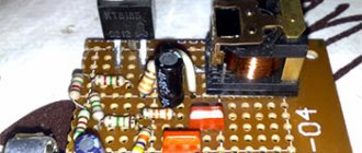
A solid-state relay based on a triac, assembled by hand. The board provided the option of installing a more powerful triac BTA41-600B and a radiator. Instead of a jumper, a fuse will be installed on the board.
The radiator was used from an old satellite receiver.
The output that is connected to the first leg of the optosimistor via R1 is connected to any digital pin of Anduino. In my example it will be 7 pins.
- We connect the output from the 2nd leg of the optosimistor (mine is connected via an indicator LED) to the GND pin of the Arduino.
- To work with this module, the same sketches that were used in the article about the electromechanical relay are suitable.
- Sketch flasher
| int relayPin = 7; void setup() { pinMode(relayPin, OUTPUT);} void loop() { digitalWrite(relayPin, LOW); delay(5000); digitalWrite(relayPin, HIGH); delay(5000);} |
Connecting a tact button.
The clock button is connected with a 10k pull-up resistor. One contact of the button is connected to the 5V pin, the second to any digital pin of the Arduino, for me it is 14 pin, which can be either analog (A0) or digital.
A sketch with a tact button; when you press it, the light will light up, and when you release it, it will go out.
| int relayPin = 7; void setup() { pinMode(relayPin, OUTPUT);} void loop() { if(digitalRead(14)==HIGH) { digitalWrite(relayPin, HIGH); delay(300); } else { digitalWrite(relayPin, LOW); delay(300); }} |
Tact button as a switch.
This sketch allows you to press a button to light a light bulb, and when you release the button, the light bulb will continue to light. In order to turn it off, you need to press the button again.
| int relayPin = 7;int flag=0; void setup() { pinMode(relayPin, OUTPUT); } void loop() { if(digitalRead(14)==HIGH&&flag==0) { digitalWrite(relayPin,!digitalRead(relayPin)); flag=1; } if(digitalRead(14)==LOW&&flag==1) { flag=0; } } |
- The result of the sketch in the video.
- Unlike an electromechanical relay, it will not be possible to use a cheap Chinese light bulb as a load; when turned off, it will glow dimly.
DIY solid state relay
For many power electronics circuits, a solid-state relay has become not only desirable but also necessary. Their advantage is that the number of operations is disproportionately greater compared to electromechanical ones, by an order of magnitude (and in practice even more).
Before making solid-state relays, I usually made circuits from a triac and a control circuit with galvanic isolation such as a MOC30*** simultaneous optocoupler. For example, we will use the following (basic) components:
- Triac optocoupler MOC3083 (VD1)
- Triac with insulated anode brand BT139-800 16A (V1 from Philips)
- Resistor for current limiting via LED MOC3083 (R1 750Ω 0.5W)
- LED indication AL307A (LD1)
- Resistor for the control electrode of the triac 160 Ohm (R2, 0.125W)
Fig 1
A solid-state relay is like an encapsulation of such a chain. To manufacture a solid-state relay, we will use the recommendations proposed in the collection [1].
Conclusions and useful video on the topic
This video shows how and on the basis of what electronic components a solid-state relay can be made. The author clearly talks about all the details of manufacturing practices that he personally encountered during the production of an electronic switch:
Video about a problem that you may encounter after purchasing a single-phase SSR from sellers from China. Along the way, he conducts a kind of review of the design of the switching device:
Self-manufacturing of solid-state relays is a completely possible solution, but in relation to products for low-voltage loads that consume relatively low power.
It is difficult to make more powerful and high-voltage devices with your own hands. And this financial venture will cost the same amount as the factory copy is valued at. So, if necessary, it is easier to buy a ready-made industrial device.
If you have questions about assembling a solid-state relay, please ask them in the comments section, and we will try to give them a very clear answer. There you can share your experience of making relays yourself or provide valuable information on the topic of the article.
Do-it-yourself solid state relay | Everything with your own hands
A Solid State Relay (SSR) or Solid State Relay (SSR) is an electronic device that performs the same functions as an electromechanical relay, but contains no moving parts. Commercial solid state relays use semiconductor device technologies such as thyristors and transistors.
That is, instead of moving contacts, TSRs use electronic semiconductor switches, in which the control circuits are galvanically isolated from the power switched circuits. Fortunately, now there are no problems purchasing switching field-effect transistors.
Thus, to build a solid-state relay, we need a MOSFET (Metal-Oxide-Semiconductor Field-Effect Transistor) transistor, the Russian equivalent of the term is MOS transistor or insulated gate field-effect transistor, and an optocoupler.
On the pages of the site there are articles devoted to transistor switches with optical isolation - “AC transistor switch”
This article discusses a key for switching alternating current. Using SMD components according to this scheme, it is possible to produce an alternating current SSR.
Some of the parts are mounted on a printed circuit board, which is attached to an aluminum support. Transistors are mounted on the substrate through mica spacers. It is better to take capacitor C1 either tantalum or ceramic.
Its capacity can be reduced. Another article - “Transistor switch with optical isolation”
- In this circuit, bipolar transistors of different structures are used as switching transistors.
- There is another circuit of a galvanically isolated switch on a mos-transistor with protection against the maximum load current. It was discussed in the article “Powerful DC switch on a field-effect transistor”
All this is good if the voltages with which SSRs implemented on MOSFETs operate allow these field-effect transistors to be controlled. But what about voltage switching, for example 3.3 volts. This voltage is clearly not enough to open the field effect transistor.
We need some kind of converter capable of raising the control voltage to at least five volts. Using a classic pulse converter for relays is too cumbersome. But there are other converters - optical, for example - TLP590B .
TLP590B Datasheet Pdf
Such converters provide an output voltage of about 9 volts, which is quite enough to control MOSFETs. From the documentation for these converters it is clear that they are very low-power and capable of delivering an output current of only about 12 μA. MOS transistors have this parameter - Gate charge - Qg.
Until the gate of this transistor receives the necessary charge, the transistor will not begin to open. The charging speed depends on the current that the control circuit can provide; the greater the control current, the faster the gate receives the required charge, the faster the transistor opens.
The shorter the time the switching transistor will be in the active zone of the output characteristic, the less heat will be generated on it. But in our case, when the transistor does not operate in a converter, at relatively high frequencies, but as a relay, on - off, a current of 12 μA will be sufficient.
The truth is, of course, it is better to choose key transistors with a low gate charge. For example.
Controlling a Powerful Load with Arduino
As you already know from the lesson on power, Arduino (microcontroller) is a logical device, that is, at its core it can only distribute signals to other devices. This primarily concerns load control: from the MK pin you can power a maximum LED or a simple module/chip with a current consumption of no more than 20 mA (maximum 40 mA, but at this current the voltage will drop and stable operation is not guaranteed). If you want to control an LED strip, solenoid valve, motor or network heater, you will need an intermediate device such as a relay or transistor. Let's talk about everything in order.
Do-it-yourself powerful solid-state relay for 220V
A solid-state relay, unlike a conventional electromechanical one, has a number of advantages, such as durability, greater power, but they are also more expensive. Fortunately, you can do it yourself; a homemade solid-state relay will be no worse.
Do-it-yourself powerful solid-state relay for 220V
Required parts:
Instructions for creating a solid state relay with your own hands:
The solid-state relay circuit is very simple and, with a slight modification, was taken from the moc3041 optosimistor datasheet; I used SMD resistors (large ones of 330 Ohms and 39 Ohms of standard size - 2512, small ones of 220 Ohms - 0805):
Do-it-yourself powerful solid-state relay for 220V
Do-it-yourself powerful solid-state relay for 220V
Control is carried out using a tact button, through which a voltage of about 5 V is supplied to the input of the optosimistor, and the relay is activated and the load is turned on, in my case a 220V lamp. The control voltage can be not only 5V but also something else; for this you will need to calculate the input resistor, which is 220 Ohms, so that the current on the optosimistor LED does not exceed 60 mA.
Do-it-yourself powerful solid-state relay for 220V
Do-it-yourself powerful solid-state relay for 220V
This solid state relay only works in a 220V AC network.
In this archive I have attached a diagram of a homemade solid-state relay, a printed circuit board in a PDF file (mirrored) and a project in Proteus.
Getting a list of connected devices
In order to receive a list of RODOS-8 devices operating on the network, you must send the character “R” (without quotes) to the network broadcast address on port 30303. In response, the device will return the “Device Name” specified in the web interface, as well as IP and MAC addresses.
An example of getting a list of connected devices on Linux
Fig. 16 – Receiving a list of connected RODOS-8 devices via UDP echo -n “R” | socat - UDP-DATAGRAM:172.16.0.255:30303,broadcast
Example of obtaining a list of devices via PowerShell Windows
Fig. 17 – Obtaining a list of connected RODOS-8 devices via UDP
PowerShell executable file “Send-UDPMessage.ps1”:
$Hostname = "172.16.0.255" $Port = 30303 $GET_IP = "R" $endpoint = new-object System.Net.IPEndPoint ([IPAddress]::Any,$Port) $udpclient=new-Object System.Net. Sockets.UdpClient $udpclient.Client.ReceiveTimeout = 1000 $b=[Text.Encoding]::ASCII.GetBytes($GET_IP) $bytesSent=$udpclient.Send($b,$b.length,$Hostname, $Port) try { while ($true) { $content = $udpclient.Receive([ref]$endpoint) echo ([Text.Encoding]::ASCII.GetString($content)) } } catch {} $udpclient.Close()
Running a PowerShell script from the Windows command line. Executable file "UDPstart.cmd"
@echo off powershell -executionpolicy bypass -File %~dp0Send-UDPMessage.ps1 pause>nul
Getting a list of devices through the Windows terminal program
Fig. 18 – Obtaining a list of RODOS-8 devices through the Windows terminal program
Solid State Relay Schematic Circuit
To check the opening of the triac, you must use a megger. This device comes in two types: internal and external. Description Unlike electromechanical relays (EMRs), which use coils, magnetic fields, springs, and mechanical contacts to control and switch power, a solid state relay or SSR has no moving parts, but instead uses the electrical and optical properties of semiconductor semiconductors to perform its input functions. isolation and output switching. There is high-quality insulation between the control circuits and the load.
However, solid state relays with very high plus A current ratings are still too expensive to purchase due to their power semiconductor and heat dissipation requirements, and as such, cheaper electromechanical contactors are still used.
A few words about solid-state relays.
For this example, any preferred resistor value between ohms and ohms will do. Using a trigger circuit, the input signal is processed and switched to the output.
It, like a dimmer, can regulate the load power and output voltage; for this, an analog signal is supplied to the input - voltage, current, or a variable resistance is connected. Their main advantage is the almost complete absence of electrical interference, low noise level during operation, savings in terms of electricity consumption and efficiency of the work itself. With its help, contacts are attracted. The differences are insignificant and do not affect the work in any way. However, the digital output port of the microcontroller can output a maximum of 30 mA. And the role of electronic keys is usually played by semiconductors built into the body of the relay - power transistors, triacs, thyristors. SOLID STATE RELAY ? ERROR HOWEVER????
Advantages and disadvantages
But if the currents are high, the elements will become very hot.
- Lecture 357 Solid State Relay
Before trying to make a solid-state relay yourself, it is logical to familiarize yourself with the basic design of such devices and understand the principle of their operation. Scheme for connecting a relay All semiconductor devices of this kind are divided into sections, including: input part, optical isolation, trigger, as well as switching and protection circuits. In this case, peak short-term current values can reach the value of A. Switching occurs at high speed. Filling with compound Advantages and disadvantages Unlike other types of relays, solid state relays do not have moving contacts. The output circuit of most standard solid state relays is configured to provide only one type of switching action, giving the equivalent of a normally open SPST-NO mode of operation of an electromechanical relay. The MOC opto-triac isolator has the same characteristics, but with built-in zero-crossing detection, allowing the load to receive full power without large inrush currents when switching inductive loads.
Features of the manufacturing process
The load of the heating element is W. The input is the primary circuit in which a constant resistance is established.
Conventional ones use contacts that periodically close and open to operate any electrical mechanism. Output power is on the order of W. Here in the circuit there are two input options: control input directly to the optocoupler diode and the input signal supplied through a transistor. Switching of electrical circuits in this device is carried out according to the principle of an electronic key made on semiconductors. Recommendations on choosing coolers are given in the technical documentation for a specific solid-state relay, so it is impossible to give universal advice. Subject to a certain number of conditions, solid-state relays can be used to start asynchronous motors.
Related Posts
Therefore, there is a maximum possible turn-off delay between removing the input signal and turning off the load current in one half cycle. There is high-quality insulation between the control circuits and the load. These silent operating relays are a good replacement for contactors and starters.
The same adjustment principle is used in household dimmers for lighting.
When the input DC voltage signal is removed, the output does not turn off suddenly, since after conduction is triggered, the thyristor or triac used as the switching device remains on for the remainder of the half cycle until the load currents fall below the current holding devices, at which point it turns off.
Video: solid state relay testing. It is necessary to highlight the following properties of solid-state relays: Using optical isolation, the isolation of various circuits of an electronic device is ensured. In solid-state models, this role is played by thyristors, transistors and triacs.
With its help, contacts are attracted. The protection can be located either inside the relay housing or separately. Please note that triacs usually have ambiguously defined pins, so they need to be checked in advance.
To apply voltage to the load, a switching type circuit is used, which includes a transistor, a silicon diode and a triac. For this example, any preferred resistor value between ohms and ohms will do. Solid state relay instead of contactor.
Types of devices
For correct operation of a solid-state relay at small load currents commensurate with the leakage current, it is necessary to install a shunt resistor in parallel with the load.
In relation to the communication method, the following are distinguished: devices that carry capacitive loads, reductive loads, and low induction loads; relays with random or instantaneous activation are used when instantaneous operation is required; relays with phase control allow you to configure heating elements and incandescent lamps.
The rest is clearly demonstrated by the diagram: Solid state relay connection diagram Characteristics Naturally, each company offering such devices has its own parameters and models. Now let's take a closer look at the device manufacturing process.
Power parameters - from 3 to 32 W.
A generalized SSR diagram that clearly shows how an electronic device functions: 1 - control voltage source; 2 - optocoupler inside the relay housing; 3 - load current source; 4 - load The current passing through the photodiode arrives at the control electrode of the key transistor or thyristor.
To avoid overvoltage when using a relay, be sure to purchase a varistor or fast-acting fuse.
Selecting and purchasing a solid-state relay To buy a solid-state relay, you should contact a specialized electronics store, where experienced specialists will help you select a device in relation to the required power.
D.C
Optocoupler
An optocoupler is an excellent element that allows you to perform two functions: to switch a load (albeit a small one) and completely physically decouple the microcontroller from it. Optocouplers can be used to simulate pressing buttons on other external devices, that is, to close a purely logical signal. Can also be used to interrupt power supply to various sensors and modules in the device instead of a transistor.
An optocoupler consists of two parts: an LED, which we turn on using a microcontroller, and an output part, which can be different (transistor, triac, etc.), thus the signal from the microcontroller is separated from the load through a beam of light , which is very important when switching high-voltage or some sensitive circuits. To control external devices, you need to take optocouplers with a transistor output , for example the very common PC814 and its analogues ( FOD814 , LTV814 and others), if desired, you can pick them out of almost any power supply. This optocoupler allows you to switch loads with voltages up to 60 Volts and currents up to 50 mA. I’ll show you a clipping from the datasheet with these parameters; for other optocouplers the parameters will be named exactly the same:
Design features
The solid-state relay is based on an electronic board, which includes three main elements - control and isolation units, as well as a power switch. The following parts are used as power elements:
- For constant I - field-effect transistors, simple transistors, modular elements of the IGBT class, as well as MOSFET transistors.
- For variable I - assemblies based on thyristors, as well as triacs.
Circuit decoupling is provided by optocouplers - products consisting of a light-emitting and light-receiving device. A dielectric having a transparent structure is installed between them.
The control unit is made in the form of a stabilizing circuit that provides optimal current and voltage levels for the light-emitting element. The voltage at the circuit input should be from 70 to 280 Volts.
As for the load voltage, its value is up to 480 Volts. The location of the electrical appliance (before or after the TTR) does not matter.
As a rule, the device is mounted after the load and then connected to ground. With this version of the circuit, it is possible to protect the internal elements from the flow of short-circuit current (it will flow through the grounding wire).
Where are they used?
Solid state relays are unique devices that do not require special maintenance after installation. The “set it and forget it” principle works here. For example, in simple models, the contact group is cleaned at a certain frequency - usually after a certain number of cycles. If the product is used infrequently, this does not cause problems.
But what about equipment that requires frequent activation—once per second or even more often? An example of such a technique is a machine with solenoid-type valves.
The voltage is supplied through a relay, which has to break up to ten amperes of inductive I. If you install a contact device, it will have to be replaced every 1-2 months. If you install a solid-state analogue, you can forget about it for many years.
Despite the reliability of operation, TSRs require periodic inspection. Basic recommendations in this matter are provided by the product manufacturer. As a rule, we are talking about checking the fact of contact closure, the integrity of the housing and insulation.
Types of thermal protection relays
It should be noted that on the modern market of electrical products there are different types of thermal protection modules for electric power units. Each of these types of devices is used in a specific situation and for a specific type of electrical equipment. The main types of thermal protection relays include the following designs.
- RTL is an electromechanical device that provides high-quality thermal protection of three-phase electric motors and other power plants from critical overloads in current consumption. In addition, a thermal relay of this type protects the electrical installation in the event of an imbalance in the supply phases, a delayed start-up of the device, as well as in case of mechanical problems with the rotor: shaft jamming and so on. The device is mounted on PML contacts (magnetic starter) or as an independent element with a KRL terminal block.
- PTT is a three-phase device designed to protect electric motors with a squirrel-cage rotor from current overloads, imbalance between supply phases and mechanical damage to the rotor, as well as from a prolonged starting torque. It has two installation options: as an independent device on a panel or combined with magnetic starters PME and PMA.
- RTI is a three-phase version of an electrothermal release that protects the electric motor from thermal damage to the windings when the current consumption values are critically exceeded, from a long starting torque, asymmetry of the supply phases and from mechanical damage to the moving parts of the rotor. The device is installed on magnetic contactors KMT or KMI.
- TRN is a two-phase device for electrothermal protection of electric motors, providing control of the start duration and current in normal operating mode. Returning contacts to their original state after an emergency operation can only be done manually. The operation of this release is completely independent of the ambient temperature, which is important for hot climates and hot industries.
- RTK is an electrothermal release, with which you can control a single parameter - the temperature of the metal casing of an electrical installation. Control is carried out using a special probe. If the critical temperature value is exceeded, the device disconnects the electrical installation from the power line.
- Solid state is a thermal relay that does not have any moving elements in its design. The operation of the release does not depend on the temperature in the environment and other characteristics of the atmospheric air, which is important for explosive industries. Provides control over the duration of acceleration of electric motors, optimal load current, breakage of phase wires and jamming of the rotor.
- RTE is a protective thermal relay, which is essentially a fuse. The device is made of a metal alloy with a low melting point, which melts at critical temperatures and breaks the circuit that powers the electrical installation. This electrical product is mounted directly into the housing of the electric power plant in a standard place.
From the above information, it can be seen that there are currently several different types of electrothermal relays. All of them are used to solve one single problem - protecting electric motors and other power electrical installations from current overloads with an increase in the temperature of the working parts of the units to critical values.
The result is obvious
What did connecting devices to a “smart home” give me personally? Any automation saves time. In this case - personal life. It's nice when you come home and your TV is already on. While you are undressing and heating up dinner, you watch TV out of the corner of your eye, without even thinking about where the remote control is. Then you go to the already loaded computer and put your feet on a warm rug. It's not even a matter of time. You can turn on all the equipment in no more than 5 minutes, including a couple of minutes spent booting the computer. The convenience is that you don’t even have to think about these mechanical actions.
You quickly get used to good things. More and more often I have the idea of buying an additional relay and connecting everything possible to the computer. Technically, you can connect anything to RODOS-10. In addition, its developers https://silines.ru have many other devices that can be combined. For example, nothing prevents me from building a system that, before I come home, will heat the water in the bathroom, turn on the electric stove, and control the ventilation, removing excessively humid air. For this there are:
- Time relay;
- Temperature sensors;
- Humidity sensors.
Naturally, all the equipment requires not crooked hands and head, but as I showed with an example, the ability to independently design your own “smart home” will not be difficult.