DIY crafts for car enthusiasts
Hi all. Many people have multimeters that are powered by a Krona battery; if the multimeter does not have an auto-shut-off, the battery quickly breaks down, even if the multimeter has an auto-shut-off, you still have to change the battery several times a year.
In this article I’ll tell you how you can get rid of the battery and switch to a lithium battery, which can be recharged by simple charging.
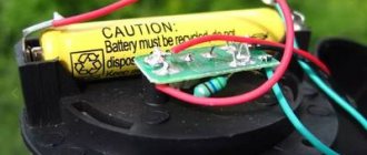
The main thing is to choose a small battery; in my case, a 3.7 Volt 400 mA battery from an old DVR was suitable.
The battery has a voltage of 3.7 volts, and the multimeter runs on 9 volts, so a voltage converter is needed. Buying a compact dc-dc converter is not a problem; the popular MT3608 boost converter board costs a penny and is affordable for everyone.
This converter has an open circuit current of about 1.5 milliamps, so even if the multimeter is turned off, current is drawn from the battery.
You can of course put a small switch,
which would turn on the battery, but we will go a different way. We will also need a charging board, which will make it possible to charge the battery from a USB port.
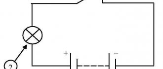
As can be seen from the block diagram, the converter is always connected to the battery and consumes some current from it, even in idle mode.
It is highly advisable to use something like this as a voltage converter
built on the ME2149 chip and similar ones, such converters can be purchased without problems in online stores. The trick of such converters is that they have a very small no-load current, a couple of hundred microamps.
Unfortunately, I didn’t have such a converter, and I didn’t want to order and wait a whole month, so I went a different route. I took the MT3608 converter and remade it a little, but I remade it because it would drain our battery in 30-40 days even if we didn’t turn on the multimeter, and that’s no good.
Therefore, it was decided to remake the converter board,
after which it began to consume a current of only 50-55 microamps, instead of 1.5 milliamps, which means that the battery will be completely discharged in 300 days, and this is already cool...
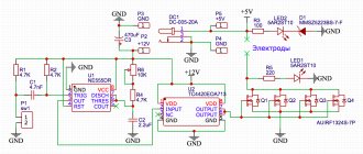
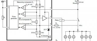
Here is the original circuit of this converter.
And here it is already redone
At the very beginning, you need to apply a voltage of about 4 volts to the input of the converter and set the trimmer resistor to 9 volts at the output, or you can simply unsolder the trimmer and solder a constant 70 kOhm resistor in its place.
Next, we take a needle or the blade of a stationery knife and cut the 4th pin of the microcircuit from the 5th pin, then assemble everything according to the diagram that was published a little higher...
You can naturally make everything more beautiful, but I did it the way I did it)
Well, just in case, a few words about the operation of the circuit.
The fourth pin of the microcircuit makes it possible to control the converter if it receives positive power, the converter starts if the ground is turned off. When turned off, the converter consumes a tiny current, 50-55 mA.
If a load is connected to the output of the converter, a certain voltage drop will occur across the resistor,
This drop is enough for the low-power transistor to work; through the open transition of the transistor, “+” power is supplied to the fourth terminal of the microcircuit, as a result of which the converter starts and at its output we get the specified voltage of 9 volts.
Remodeling does not take much time and costs almost no money. A transistor of any low or medium power, I advise you to take a transistor with a high current gain.
I had to cut down the MT3608 board to fit into the case, and I added a 10 uF electrolyte to the output to smooth out the ripples.
The standard charging system is built on the basis of the TP4056 microcircuit; the board has a charge indicator and a protection board for the battery.
This module will allow you to charge a lithium battery from a regular USB port with a current of up to 1 ampere, since my battery has a capacity of 400 milliamps, I reduced the charge by 2 times by replacing the current-setting resistor on the board...
The table depending on the charge current of the resistance of this resistor is now in front of you
This board also had to be cut down, the battery protection system was thrown out, since the battery itself already had such protection.
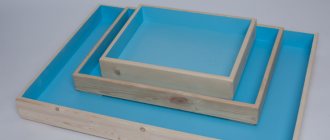
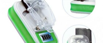
I printed the case on a 3D printer,
Well, you can place this craft at your discretion, you can also place everything without the case, the only thing you need to do is cut out a window for the charge socket. You can also use the case from an old, used Krona battery. Take all the guts out of it, insert our boards and fill it with glue.
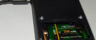
Well, now let’s test what we’ve got, insert our “battery” into the multimeter, as we see the voltage on the battery is about 4 Volts, this means that our converter is in sleep mode and consumes an insignificant current from the battery.
Now we turn on the multimeter and again check the voltage on the “batteries”, as we see it is already around 8 volts, this means that the system responded to the load and the converter started up. Everything works great, otherwise the multimeter would show a low battery icon.
This device, that is, the “battery,” is specially designed to power a multimeter.
Of course, you will have a completely fair question - Why is all this necessary, when you can buy a battery and not worry?... But I’ll answer you simply, I’m interested in making crafts with my own hands so that they work and bring benefits in the future, but go to the store and just buying is not for me.
Author; AKA KASYAN
Popular;
- Do you need to wash your car battery?
- How to charge a car battery from a laptop power supply, diagram
- Scheme of a simple battery charger with auto shutdown
- Car battery diagnostics using one voltmeter
- A good adapter for a laptop from 12 Volts
- How to easily make car lamps brighter.
- Automatic charger with auto shut-off.
- Charger for a car from a power supply from an LED strip
Refinement of the multimeter mount
Another inconvenience when taking measurements with a multimeter is the lack of a third hand. You constantly have to hold a multimeter in one hand and use the other to work with two probes at the same time.
If measurements take place at your desk, then there is no problem. Put the tool down, free your hands and work.
What should you do if you measure the voltage in a panel or in a distribution box under the ceiling?
The problem can be solved simply and inexpensively. In order to be able to mount the multimeter on a metal surface, glue ordinary flat magnets to the back of the device using hot-melt adhesive or double-sided tape.
And your device will be no different from expensive foreign analogues.
Another option for inexpensive modernization of a multimeter in terms of its convenient placement and installation on a surface when taking measurements is to make a homemade stand. To do this, you only need 2 paper clips and hot glue.
And if you don’t have any surface nearby where you can place the tool, what should you do in this case? Then you can use an ordinary wide elastic band, for example from suspenders.
You make a ring out of an elastic band, pass it through the body and that’s it. Thus, the multimeter can be conveniently mounted directly on your hand, like a watch.
Firstly, now the multimeter will never fall out of your hands again, and secondly, the readings will always be before your eyes.
Multimeter backlight
A function that the multimeter lacks in poorly lit areas is display backlighting. Solving this problem is not difficult, just apply:
- 2 LEDs soldered in series to each other
- reflector - ordinary piece of gold from chewing gum
- microswitch of any type
Make a hole in the side of the housing for the switch. Glue the reflector under the indication display and solder two wires to the crown contacts.
They supply power to the switch and then to the LEDs. The structure is ready.
The final result of a homemade modification of the multimeter backlight will look like this:
The backlit battery will be used up much faster, so do not forget to turn off the switch when there is enough natural light.
Small details.
It was difficult to purchase just one battery. They are mostly sold either in pairs or in groups of four. However, some kits, for example, “Varta”, come with five batteries in a blister. If you are as lucky as I am, you will be able to share such a set with someone. I bought the battery for only $3.3, while one “Krona” costs from $1 to $3.75. There are, however, also “Crowns” for $0.5, but they are completely stillborn.
March 19, 2012 (15:23) in Power supplies, DIY
Caps for probes
The spikes at the ends of the probes are quite sharp, which can hurt you. Some models come with protective caps, some do not.
They also get lost quite often. But in addition to the danger of pricking your finger, they also protect the contacts from breaking when the multimeter is in a bag mixed with another tool.
In order not to buy spare ones every time, you can make them yourself. Take an ordinary cap from a gel pen and lubricate the tip of the dipstick with any oil. This is done so that the cap does not stick to the surface during the manufacturing process.
Then fill the inner surface of the cap with hot glue and place it on the sharp tip.
Wait until the hot glue hardens and calmly remove the resulting result.
Disassembling a nine-volt Krona battery.
To complete this project, I carefully bent the rolled edge of the back of the tin housing.
In the corners I bent the folding using a thin screwdriver.
Using pliers, I smoothed out the deformed edge of the shell.
Removed battery sections.
I drilled a hole with a diameter of 6mm in the back wall and screwed in a standard socket for a 3.5mm Jack so that the built-in battery could later be charged without disassembly.
The procedure for winding a pulse transformer.
It is very difficult to wind a gasket onto a ring core of such small dimensions, and winding a wire onto a bare core is inconvenient and dangerous. The wire insulation may be damaged by the sharp edges of the ring. To prevent damage to the insulation, dull the sharp edges of the magnetic circuit as described here.
To prevent the turns from running apart when laying the wire, it is useful to cover the core with a thin layer of “88N” glue and dry it before winding.
First, the secondary windings III and IV are wound (see converter diagram). They need to be wound into two wires at once. The coils can be secured with glue, for example, “BF-2” or “BF-4”.
I did not have a suitable wire, and instead of a wire with a calculated diameter of 0.16 mm, I used a wire with a diameter of 0.18 mm, which led to the formation of a second layer of several turns.
Then, also in two wires, primary windings I and II are wound. The turns of the primary windings can also be secured with glue.
I assembled the converter using the hinged mounting method, having previously connected the transistors, capacitors and transformer with cotton thread.
The input, output and common bus of the converter were connected with a flexible stranded wire.