Planning to buy +97 Add to favorites I liked the review +136 +240 My version of spot welding on an Atmel AVR ATtiny48 using a transformer from an old microwave.
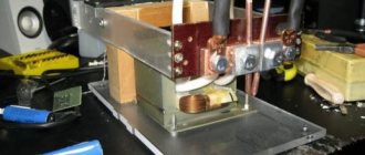
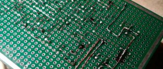
A two-segment LED display, buttons and a buzzer are used. Transformer switching through a triac. Pulse time 0.1 - 99 seconds and start/stop manually (when the value on the display is 0). A transformer from a non-inverter stove, with a capacity of about a kilowatt (the more, the better). The thin winding of the transformer is carefully removed with a hacksaw, and the metal magnetic jumper between the windings, which limits the power, is removed. A thick wire in insulation larger than 10 mm in diameter is inserted into the resulting gap - 2 turns. I used a truck to connect the battery. The ends of this wire are screwed to copper rods about 15 mm thick. The rods are sharpened. For indication, a two-segment indicator is used, connected directly to the controller, the controller has a lot of outputs, so I didn’t bother with dynamic display. Each display is connected through one resistor - I was too lazy to solder it to each segment. The difference in brightness is not particularly noticeable. The control unit has 3 buttons - up, down, select/pulse. The passive beeper informs about button presses and warns before an impulse. The program is written in C in Atmel Studio 6.0. There is a settings mode (Setup function) - enter by simultaneously pressing the up and down buttons. Settings: 1. Delay before impulse in seconds 2. Shows the number of operations in tens. 3. Controller temperature 4. Calibration of internal generator. The frequency of 15625 Hz is displayed on the tweeter; OSCCAL is adjusted using the buttons. The display shows the value in hexadecimal. 5. 60 second cycle to check the built-in generator. Button chatter is eliminated by means of a delay (timer 0 is used). After the PCINT1 interrupt is triggered by changing the value of the pins, the interrupt comparing TCNT0 and OCR0A of timer 0 is activated and we wait for the interrupt to trigger. In it we already get the state of the buttons. Long press the buttons to quickly change time/settings. The Watchdog interrupt is used for this and also to flash the LED. I decided to pervert myself this way. Hang reset is not used. For display output, its own microlibrary is used. Scheme: Files in the topic: Welder.zip Only registered and authorized users can leave comments.
we.easyelectronics.ru
Spotter from an old microwave: how to make it yourself
In order to make a device with your own hands, with which you can straighten dents on a car body, it is not at all necessary to thoroughly know electrical engineering and purchase expensive components. For these purposes, you can make a spotter from parts taken from a microwave oven that has expired, as well as from other equally accessible structural elements.
Homemade spotter assembly
Electrical part of a homemade spotter
The most important element of any spotter operating on the principle of resistance welding is a transformer. It is quite difficult to find and inexpensively purchase an already assembled transformer that can ensure the efficient operation of such equipment, so it is better to make it yourself. As a basis for the manufacture of such a device, you can use a transformer from a microwave oven.
Microwave transformer: old secondary winding removed, new one installed
In order for your equipment to provide enough current to weld the washer, it is better to take two transformers from the microwave. It is necessary to carefully remove the secondary windings from them, and wind new ones in their place, for which a wire with a cross-section of 50 mm2 or more is used. The number of turns on the secondary winding of each such transformer should be 2–3. In this case, your homemade equipment will generate a current whose strength will be sufficient to perform welding.
The process of making a simple homemade spotter made from two transformers from microwave ovens can be seen in the video below:
The transformer is not the only element of the electrical system of a homemade spotter. It will also include:
- a transformer that supplies power to the equipment control unit;
- thyristor;
- diode bridges;
- variable resistor.
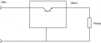
Spotter electrical circuit
A simple circuit assembled from these elements ensures the formation of a powerful electrical impulse and its supply to the spotter electrode.
Ensuring convenience and safety of work
To make it not only convenient but also safe to work with the spotter that you make yourself from microwave parts, you need to place all its structural parts in a neat and reliable case. Such a housing will, in addition, protect the electrical part of the equipment from mechanical damage and contamination, which can quickly render it unusable. You can also use a part from an old microwave - its body - as a protective casing.
The basis of a homemade spotter can be any suitable sized body
Before placing the electrical unit of the device into the microwave housing, it is necessary to securely fasten all its parts to the base, which is best made of dielectric sheet material. When placing the elements of the spotter's electrical unit on the base, you need to distribute them evenly over its entire area: this will make your equipment more convenient to carry. In addition, small wheels that can be attached to the bottom of the base will give the homemade device additional mobility.
Once all the electrical components of your equipment are placed in the old microwave case and securely fastened in it, you need to take care of the other parts that you will not be able to work without. These elements are:
- electrical cables used to connect the welding transformer to the electrodes of the equipment;
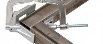
- a gun in which the spotter electrode will be fixed;
- devices for pulling metal using welded washers: reverse hammer or inopuller.
A reverse hammer and a gun are the working elements of a spotter
Knowing the current generated by your homemade spotter, you can calculate the cross-section of the cables through which the current will flow. Usually they are guided by the following rule: for 10 A of current there should be 1 mm2 of electrical cable. In addition to the cross-section, the length of the wires going to ground and to the welding electrode is also important; it should be as short as possible in order to minimize current losses.
Gun for homemade spotter
If you've spent time making a homemade spotter from microwave parts, don't be lazy and make a convenient and safe gun for it. In order to make such a holder on your own, you will need a thick sheet of getinax or textolite, from which two identical pistol-shaped blanks are cut out (they should fit comfortably in your hand). A power button and a bracket for attaching the electrode are placed in a special recess that must be made in one of these blanks.
Assortment of consumables for spotter
You can also make an electrode for your homemade spotter yourself, using round copper rods, bronze or copper tubes, which are very convenient to connect to a current supply cable. On the side of the working part of the electrode, it is necessary to make a slot into which a washer will be inserted for welding. If you use a tube to make an electrode, then its working end must be flattened and only then made a corresponding slot on it.
To work with the spotter, you will also need a reverse hammer, which you can make yourself. It is best to use a mounting gun to make such a device, slightly modifying its design. You can see how to quickly and cost-effectively make a reverse hammer in the video that many home craftsmen post online.
As you can see, it’s not at all difficult to make a spotter yourself using an old microwave and other unnecessary parts that have been stored in your garage or home workshop for years.
met-all.org
Electrical circuit layout of printed circuit board
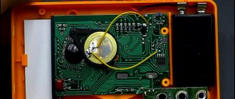
Two blue LEDs connected in series begin to glow just at a voltage of 5 V. They form a battery readiness indicator. I added a yellow electrode contact indicator. I made a circuit and laid out the board in the EasyEDA editor
Circuit based on SMD components
Resistance welding from a microwave and a homemade timer on PIC
- AliExpress
- Made by hands
- Products for professional use
Let's continue the cycling topic.
When I rode a bicycle to work, it was inconvenient to carry it in a backpack - my back sweats. It’s inconvenient to carry on the trunk - the bag slides and tries to get into the spokes. You need a small basket for the trunk that would keep small loads from falling. Since they don’t make such small baskets, I decided to make them myself. To assemble such a basket you need resistance welding, which can also weld batteries. The process of assembling the trunk basket, batteries, and welding itself is described below. The “welding body” is a transformer from a microwave oven.
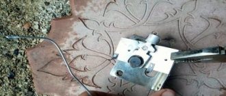
The secondary winding was removed with a hacksaw, and the plates between the primary and secondary were removed. I recommend a hacksaw; a Dremel or grinder can easily damage the primary winding, but it is still needed. A PV3 wire of 70 square millimeters was inserted (stuffed, hammered) into the window of the secondary winding in 4 hands, 1 meter is enough. The wire goes very hard, it took two people to refuel. Tinned copper lugs were soldered onto the wire with a gas torch; it was not possible to solder pure copper ones. Electrodes are attached to the tips - 10 squares of copper for welding batteries and rectangular ones for welding rods or sheets.
In the case of rectangular electrodes, they allow you to weld both wire, if the electrodes are placed plane to plane, and a sheet if you turn the top electrode at an angle, as in the photo. Rectangular electrodes are plates from the installation kit for current transformers; they were not useful during electrical installation, but here they are.
“Welding Brains” is a homemade timer on the PIC16F628A microcontroller, the link to which is in the title of the review.
I purchased it from the Chinese Super Electronic market, it’s not the first time I’ve made it there, and I don’t think it’ll be the last. When ordering $15-30, it is sent by mail with a normal track, well packaged, and does not mess with the package. Moreover, his prices are usually minimal or close to them. In addition to picukha, it was purchased
A set of quartz resonators for all occasions, 10 items of 5 pieces each - $2.7 lot 50 pieces.
5V stabilizer chip 50 pcs $1.28 - Powerful thyristors BTA41-600 10 pcs $4.8 - Optocoupler 10 pcs $1.6 - PIC itself - 10 pcs $13.8
Based on the diagram from the article
The power part was taken from the circuit, and it was decided to write the firmware myself. I didn’t like the use of two buttons in the circuit - it’s faster and more convenient to control the encoder, the shutter speed range is small.
I reviewed the power supply right there; a 5V stub was added to it. Two supply voltages 5V main and 12V control go to the controller. When the power is turned off, the 12V voltage begins to drop first; it goes through a resistive divider to the controller leg (blue trimmer, set to 3V). The controller sees zero on the leg, saves the parameters and goes to sleep.
The output of the PIC leg gives a signal to the optocoupler, the optocoupler opens the thyristor, which in turn turns on the trans primary. No heating of parts was noticed. It is possible to use a solid state relay, as in the previous article on this resource. I also used a solid body in my previous welder, but the optocoupler + thyristor is smaller and cheaper when purchased in 10-piece quantities.
The encoder was purchased like this:
It already has pull-up resistors, the encoder not only rotates but is also pressed. When you press the encoder, the number begins to blink smoothly (I changed the brightness according to a sinusoid) - it shows the number of pulses up to 9, that is, you can cook with a repeated or triple pulse, the pause between pulses is equal to the pulse duration, the duty cycle is 50% in general. When you press the encoder again, it remembers the parameter into memory (checks whether it has changed) and goes back to the operating mode. Indication on two LED seven-segment indicators, dynamic indication. When welding, you usually need both hands free; to start welding, a pedal was made - a bell button. When turned on, the timer for 1 second shows and reminds the number of pulses. Then the shutter speed indication.2 -0.02 sec 0.2 -0.2 sec 2.2 -2.2 sec. maximum 9.9 seconds, minimum 0.01 sec. When you press the pedal and practice the shutter speed, it is shown - - The tweezers should not twitch when practicing the shutter speed, it didn’t turn out very clearly. timer operation 1.33 min
Physically, the timer is assembled in the housing of the HP printer power supply; a board is used from it as a supporting element and a power connector, fuse and filter capacitors at the input. Something is assembled on stands, something is glued with hot glue, in general, all the elements of the collective farm. Oddly enough, everything works.
The faint of heart and perfectionists should not look at photos of offal
welding nails 4+4mm.
Result after
Welding result
Luggage racks, 1 kg of galvanized wire 3 mm was enough for both luggage racks, price about 1.5-2 $ Mine cell 4*4cm, wife for a bike bag cell 5*5 cm Welding batteries for screwdrivers leftover galvanization
UPD. Added larger photo
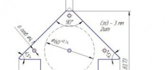
Brief description of the principle of operation and assembly: Resistance welding is the process of forming a permanent welded joint by heating the metal with an electric current passing through it and plastic deformation of the joint zone under the action of a compressive force. (Vicki) That is, you need a lot of current and compression force. In industrial devices, the compression force and current are regulated electronically; there are welders with hydraulic compression. The simplest ones are those where they are squeezed with their hands, as in my version. Current is still needed. The transformer from the microwave allows you to replace the secondary winding; instead of the step-up winding, we install a step-down winding. The voltage does not matter much; the current is sufficient. When using larger transformers, damage to the wiring is possible; the primary winding currents in the microwave transformer are around 15-20 amperes, a good home option. In addition to the power part, which provides current and sometimes pressure, sometimes an electronic part is needed. You can put a 16A circuit breaker in the primary winding, like in an access panel, and use it to set the time delay of the current effect by hand “by eye.” For example like this
If you want a little convenience, holding both with both hands, you can add a button. But not every button can withstand currents of 15 amperes; for this you can use a solid-state relay or a starter. If the starter coil or solid state relay input is low voltage, not 220V, then a power supply is needed. This option is in the next picture.
The power supply provides 12 or 24 or any other safe voltage, it turns on the relay/starter through the K button, it is convenient to press with your foot and the button does not burn out. For long shutter speeds of the order of 2-5 seconds and large details, this is acceptable. But when welding batteries, plates 0.1-0.2 mm thick are usually used and short dwell times of the order of 0.01-0.1 seconds are required. Such shutter speeds are difficult to work out manually; exceeding the shutter time will burn out the plates, and sometimes even the battery, and they are not cheap. To ensure repeatability of the result, an electronic timer is installed, which generates the necessary short exposures. The next picture shows a circuit with a timer.
In total, almost the most advanced option - a transformer with a replaced secondary, a timer button, a power supply, you can combine it to your taste. For example, if the timer is 220V, then a power supply is not needed, but your leg may get fried if there is 220V on the pedal. Brief assembly instructions: -Find a microwave, disassemble, remove the trans (it is 2/3 of the weight of the microwave). -Check whether the primary winding is alive, it is usually wound with a thicker wire, ring. Do not turn on! High voltage may appear on the secondary winding and transformer housing. -Carefully remove the winding with the thinnest wire, if the thick one is live. Clamp it in a vice, cut it with a hacksaw or any other not very powerful tool, the remains will be knocked out. -Remove the shunts (plates between the primary and secondary windings). -There are several more turns of the filament winding. It can also be deleted. -Wind the secondary winding into the vacant window. For welding batteries, 35 squares of copper are enough, for thicker materials 70-100mm. You may have to remove the factory insulation and insulate with heat shrink/duct tape. Two or three turns is usually sufficient. The wire is called PV3*70 or welding wire. Maybe PV5*70, but I haven’t seen those. -End the wire. Typically, tinned copper lugs and copper lugs are used. You can crimp or solder them or both. -Attach electrodes to the ends of the wire. To weld batteries, 10 squares of copper (PV3*10) are enough. For thicker metals, electrodes are made from large-diameter copper rods, sharpened at the ends. The better the connection between the electrodes and the wire and the shorter the wire, the greater the current and the better the welding. — Add a timer, button, body to taste. You can add an LED to the upper electrode arm to illuminate the work area. You can add another winding of 3-5 turns and solder a 5V buzzer to it (the white wire is in my photo), it will beep when welding. Link to the proteus project
drive.google.com/open?id=0B0G2PPYK72EgOXF4eDNxTkMtWkE
Not good at proteus, but it seems to work. link to firmware
drive.google.com/open?id=0B0G2PPYK72Egc1lfT0t2OHFyTUE
RV2 adjust to 3v, lower log. 0 and the command goes to save to memory. Motor-encoder, two buttons to turn it, a trigger button and an encoder button, ports B for the indicator - ABCDEFG-2345610 indicators I have sc56-11gwa, that is, a common cathode. The title of the oscillogram shows the shutter speed in seconds. In the first, the shutter speed is 0.01 seconds, pulses one at a time manually, to the right 5 pulses at 0.01 each, the rest are all 5 pulses automatically after a pause equal to the shutter speed.
This is a video from a previous welder, there are 3 turns *35mm. The wire is thinner and more flexible, the essence is the same.
Plate 0.1*4mm
Planning to buy +127 Add to favorites Liked review +160 +286
mysku.ru
Required materials
- Timer NE555
- MOSFET TC4420 driver
- Power switches IRF1324 - 4 pcs.
- Ionistors for 3000 F 2.8 V - 2 pcs or 3 pcs (for version 7.5V)
- Power supply 5 V 3 A or PSU 7.5 V (for version 7.5V)
- Gerber PCB file
- Or a development board like in the video
- Potentiometer 10kOhm
- Soft wire for connecting electrodes PUGV 1x6 mm2 - 1 m
- Rigid wire PuVng 1x4 mm2 - 0.1 m
- Terminal blocks for making an electrode handle
- Ferrules for wire 6x6 mm2 - 4 pcs or 6 pcs (for version 7.5V)
- Blue LED - 1 pc.
- Zener diode BZX55C3V9 at 3.9V or BZX55C5V1 at 5.1V (for the 7.5V version) - 1 pc.
- Yellow LED - 1 pc.
- Resistor 4.7 kOhm 1206 — 2 pcs.
- Resistor 2.2 kOhm 1206 — 1 pc.
- Resistor 100 Ohm 1206 - 1 pc.
- Resistor 220 Ohm or 390 Ohm (for version 7.5V) 1206 - 1 pc.
- Capacitor 4.7 nF 50 V 0805 — 1 pc.
- Capacitor 2.2 uF 25V 1206 — 1 pc.
- Electrolytic capacitor 470 uF 25V - 1 pc.
- Power socket
- Green button
- Power button
- DC-DC booster 5V - 12V or Schottky diode 1N5818 (for 7.5V version)
- Stl file 3D model of the case for printing
Making spot welds from the microwave
- November 21
- 12 rating
- Removing and disassembling the transformer
- Assembling the transformer and installing a new winding
Very often in the household there is a need for spot welding.
In spot welding, the metal is heated by passing heat from one part to another through the place of their contact.
At home, you can make spot welding from the microwave. The spot welding machine is ideal for welding stainless steel and galvanized sheet steel up to 1 mm thick.
Where can I buy
You can purchase a ready-made timer or time relay either in a specialized store or online in an online store. In the second case, the budget option for purchasing products on the Aliexpress website deserves special attention. For some devices there is an option for shipment from a warehouse in the Russian Federation; they can be received as quickly as possible; to do this, when ordering, select “Delivery from the Russian Federation”:
| Digital time delay relay module | Timer switch | Electronic time relay GEYA with delay |
| Universal time relay with a range from 1 to 60 minutes | Digital programmable timer TM618H | Digital time relay with display |