A temperature sensor assembled with your own hands can bring undoubted benefits both in the home and in the garden. The ambient temperature controller will promptly turn on or turn off the fan, heater, boiler, heated floors and many other appliances in the house, heat or ventilate greenhouses. If you have minimal experience with tools, making a temperature sensor with your own hands will not be difficult.
Principle of operation
The idea of creating a temperature sensor is that it uses an electrically conductive element, which, under the influence of fluctuations in ambient temperature, changes its resistance. Such an element is a thermistor.
The operating principle of variable resistance is that when heated, the resistance decreases and the current flowing through it changes its characteristic. This process is reflected in the operation of the application circuit, which turns on or off the corresponding devices.
Advantages and disadvantages
Even a simple do-it-yourself thermostat has a lot of advantages and positive aspects. There is no need to talk about factory multifunctional devices at all.
Temperature regulators allow:
- Maintain a comfortable temperature.
- Save energy resources.
- Do not involve a person in the process.
- Follow the technological process, increasing quality.
The disadvantages include the high cost of factory models. Of course, this does not apply to homemade devices. But the production ones, which are required when working with liquid, gaseous, alkaline and other similar media, have a high cost. Especially if the device must have many functions and capabilities.
Assembly
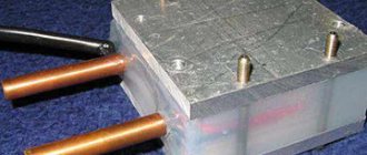
Having prepared the above materials and tools, we proceed to soldering a simple circuit.
- The positive terminal of the power supply is connected by a wire to the input contact (+) of the cooler;
- The three terminals of the field-effect transistor are soldered with wires like this: “source” with a cooler, “gate” with a thermistor, “drain” with a variable resistor.
- Wires connect the free contacts of the thermistor to the “+” of the power supply, and the variable resistor to the “−” of the same block.
Using Arduino
There are many circuits describing a digital thermometer using an Arduino microcontroller. All of them uniformly take the measured temperature from the sensor and display it on the display, which is quite small in size. That is, of course, such a system can be used outdoors, but the display screen needs to be placed closer to people or even mounted indoors.
What is good about a microcontroller is that not only a digital indicator can act as a scale. Although the latter also has the right to life, for reading readings in places where the street informant is not visible. As for the latter, in its role you can use a long homemade ruler (which can also be an ordinary board of any size), with markings and an arrow moved by a servo drive, demonstrating the current temperature values.
Mechanism
The general design of the mechanism is as follows:
The lower and upper ends of the scale are determined by the physical position of the installed switches, which are closed by a movable pointer when the marked length limit is reached. The latter is required only for the initial calibration of the mechanism when the system is first started.
To ensure that the accuracy of the presented meter is not influenced by external weather factors (the moving string and guide lengthen in the heat and contract in the cold), it is recommended that the upper roller and supporting wire be secured to rigid springs “in tension.”
Scheme
A few notes on the diagram. The TM1637 digital indicator is used to display temperature information numerically. Additionally, the previously described mechanism displays the value on an “analog” scale using a bipolar clock motor M1. S1 is a blocking switch installed at the top of the scale, S2 at the bottom.
Examination
Test the thermostat in this order:
- bring a burning match or lighter to the thermistor and the cooler should start working;
- when cooling, the fan should turn off;
- if the circuit does not work, you need to recheck the soldering and contacts.
TR - thermistor, K - cooler, R1 - variable resistor, PT - field-effect transistor, AB - 12 V battery.
Simple electronic
In order to make an electronic thermometer, a slightly more complex design is required. The temperature indicator in it is an ammeter with a sensitivity of 50 μA, and the sensor is an STZ-19 type thermistor with a unary resistance rating of 10 kOhm. The latter has many analogues from various manufacturers, in case it is not possible to find the original of the indicated marking.
So, to create an electronic thermometer, you will need:
| Designation on the diagram | Name | Analogs |
| VT1, VT2 | Transistors KT315A | KT3102 (A, B, C, D) |
| S1 | Power switch | |
| R1 | 68 ohm resistor | |
| R2 | Variable resistor 680 Ohm | |
| R3 | Variable resistor 22 kOhm | |
| R4, R5 | Resistors 6.2 kOhm | |
| R6* | -//- 9.1 kOhm | |
| R7* | -//- 910 Ohm | |
| R8 | Thermistor STZ-19 10 kOhm | |
| GB1 | Two 1.5 V AA batteries | |
| S2 | Two-position operating mode switch calibration/measurement | |
| PA1 | Any microammeter with a limiting pointer position of 50 µA. It is desirable to have the longest scale length for subsequent ease of marking. |
Thermal sensor on germanium diodes
A feature of germanium semiconductor diodes is their high sensitivity to changes in air temperature. Therefore, these radio components can be used as temperature sensors when they are turned back on.
Their use is explained by the strong dependence of the reverse current on the ambient temperature. This feature of the diodes is used in a simple cooler speed controller circuit.
Germanium diodes connected in parallel (3–4 pieces) are connected in the opposite direction to the base circuit of the composite transistor. Their glass cases can be mounted directly on the cooler without any heat sinks. Resistor R1 protects the transistor from thermal breakdown, and R2 determines the response threshold of the regulator. If the fan does not turn on when the room temperature is exceeded, then the number of diodes must be increased. When the cooler begins to rotate the blades at high speed, the number of radio components is reduced.
Setting up the thermostat
As already mentioned, a thermostat based on the LM335 sensor does not need adjustment. It is enough to know the voltage supplied by the potentiometer to the direct input of the comparator.
It can be measured using a voltmeter. The required voltage value is determined by the above formula.
If you need, for example, for the device to operate at a temperature of 20 degrees, it should be 2.93 V.
If any other element is used as a temperature sensor, the reference voltage will have to be checked experimentally. To do this, you need to use a digital thermometer, for example, TM-902S. For precise adjustment, the thermometer and thermostat sensors can be connected using electrical tape, after which they are placed in an environment with different temperatures.
Thermostat made from scrap materials
The potentiometer knob must be rotated smoothly until the thermostat operates. At this moment, you should look at the scale of the digital thermometer and apply the temperature displayed on it to the scale of the thermostat. You can determine extreme points, for example, for temperatures of 8 and 40 degrees, and mark intermediate values by dividing the range into equal parts.
If you don’t have a digital thermometer at hand, the extreme points can be determined by water with ice floating in it (0 degrees) or boiling water (100 degrees).
When faced with choosing a heater, people discover that there are many types of devices, but you need to choose one. Ceramic heater for the home - subtleties of the right choice, review of models and prices.
Air humidity standards and methods for measuring it are presented in this topic.
Using a thermal sensor on Arduino
To assemble a temperature meter based on an Arduino microcontroller, you need to prepare the following:
- Arduino UNO;
- connectors;
- circuit board;
- digital module DS18B20 (range from −56 to +1250 C).
The DS18B20 digital temperature sensor is a device that not only signals when a specified temperature threshold has been exceeded, but can also store measurement values. The sensor chip has three output contacts - “+”, “−” and a signal wire. The waterproof temperature sensor is used to measure the heating of water or liquids.
A temperature sensor can always be purchased, like an Arduino board, in online stores. The digital module is connected to Arduino via GND channels, and the Vdd output is connected to 5V, Data to any Pin. For a clearer understanding, the connection diagram of the DS18B20 digital sensor to Arduino is shown in the photo below.
Do-it-yourself temperature controller parts
The temperature sensor is usually a thermistor - an element whose electrical resistance changes depending on the temperature. Semiconductor elements are also used - transistors and diodes, the characteristics of which are also influenced by temperature: when heated, the collector current (for transistors) increases, while a shift in the operating point is observed and the transistor stops working, not responding to the input signal.
But such sensors have a significant drawback: they are quite difficult to calibrate, that is, “bind” to certain temperature values, which is why the accuracy of a homemade thermostat leaves much to be desired.
Meanwhile, the industry has long mastered the production of inexpensive temperature sensors, the calibration of which is carried out during the manufacturing process.
These include the LM335 device from National Semiconductor, which we recommend using. This analog temperature sensor costs only $1.
“Troika” in the first position of the digital row in the marking means that the device is intended for use in household appliances. Modifications LM235 and LM135 are intended for use in industry and military applications, respectively.
Having 16 transistors, this sensor works like a zener diode. Moreover, its stabilization voltage depends on temperature.
The dependence is as follows: for every degree on the absolute scale (Kelvin) there is 0.01 V of voltage, that is, at zero Celsius (273 Kelvin) the stabilization voltage at the output will be 2.73 V. The manufacturer calibrates the sensor at a temperature of 25C (298K ). The operating range is from -40 to +100 degrees Celsius.
Thus, when assembling a thermostat based on LM335, the user is freed from the need to select, by trial and error, the reference voltage at which the device will provide the required temperature.
It can be calculated using a simple formula:
V = (273 + T) x 0.01,
Where T is the temperature of interest to the user on the Celsius scale.
In addition to the temperature sensor, we will need a comparator (LM311 brand from the same manufacturer is suitable), a potentiometer for generating a reference voltage (setting the required temperature), an output device for connecting a load (relay), indicators and a power supply.
The thermostat is an integral part of autonomous heating. The thermostat for the heating boiler will help maintain the temperature in the house at a comfortable level.
We will discuss the operating principle of the thermostat for an infrared heater here.
Is it worth installing a thermostat for a heating radiator? In this article https://microklimat.pro/otopitelnoe-oborudovanie/otopitelnye-pribory/termoregulyator-dlya-radiatora-otopleniya.html we will consider the purpose of the device and the types and features of installation.
Connection options
- To the heated floor system;
- To the heating element;
- To the heater.
Connecting a thermostat to a heated floor system
A standard underfloor heating thermostat is supplied with detailed instructions for connecting the device to the underfloor heating system. You can connect the TP yourself using the markings under the terminal blocks.
Underfloor heating mat
On the back of the regulator there are three pairs of terminal sockets for wires. The first pair is intended for connecting a two-core network cable. Socket “L” – phase, “N” – zero.
The second pair of sockets is intended for connection to the underfloor heating terminals – L1 and N1. The fifth and sixth terminals are used to connect to the temperature sensor.
Connecting the thermostat
Floor temperature regulators can be inserted into a socket box or mounted on the wall. The temperature sensor can be either built into the body of the device or installed at the end of an external cable.
In the first case, the air temperature inside the room is measured. In the second option, the sensor measures the degree of heating of the final floor covering.
Connecting the thermostat to the heating element
The thermostat must be connected to the electric heater through a magnetic starter. This is due to the fact that the power of the regulator is far from comparable to the power of heating elements.
A magnetic starter (MP) is needed when the thermostat controls several heating devices at once. The MP is cut into the phase wire in parallel with the thermostat. Adjustment of the operating modes of the heaters is carried out by a thermostat, the supply current passes through the MP. This makes it possible to use a three-phase power supply, which allows the operation of high-power heating elements.
Many TRs are equipped with electronic microprocessors, which additionally provide indicators of the level of humidity, pressure and time required to achieve the values of the specified parameters.
Connecting the thermostat to the heater
Thermostats can be mechanical or electronic. Recently, the second models have been actively displacing their mechanical counterparts. The use of modern electronics makes it possible to more effectively control the temperature in a given environment.
TRs for room heaters are built into heater housings or placed away from heating devices. The regulator, first of all, is connected to the electrical network, then through the control circuit it is connected directly to the temperature sensor.
Additional Information. In most cases, infrared heaters are connected to a thermostat via a magnetic starter. To connect the device correctly, you must strictly follow the instructions provided.
Features of how temperature control devices are connected depend on the type of heating devices. This can be a single-core or two-core connection of TP underfloor heating. The connection of a two-phase thermostat to three-phase current heating elements is carried out only through a magnetic starter. For water heating, the thermostat is embedded directly into the radiator. Each specific case has its own thermostat connection diagram.
What is tempera made from?
Inexpensive models are made of aluminum and plastic. Plastic presses do not perform their primary functions very well. Due to insufficient weight, the result during pressing will be insufficient. Tools made of plastic quickly fail and are short-lived. Sometimes it is easier to replace the tamper with a better one rather than purchasing another one made of plastic.
The aluminum work surface lasts longer. Its peculiarity is that the material is susceptible to small scratches.
The best raw materials for the working part of the distemper:
Parts are made on lathes. Wizards set certain forms and parameters. Hand grinding is the most reliable. Suitable diameters for coffee makers: 51 mm, 52 mm, 53 mm, 55 mm, 57 mm and 58 mm. The last two are used for professional coffee machines.
The handles are made of wood and aluminum. Expensive models made from valuable wood species are in particular demand. The walnut or maple handles last a long time and are also very comfortable. Mandatory processing of the handles: craftsmen give them an ergonomic shape, then grind and impregnate them with oil. The last final stage is varnishing.
Aluminum elements are coated with special powder paint. Craftsmen use anodizing techniques to prevent the metal surface from oxidizing.
general description
A room thermostat for a gas boiler consists of 2 metal strips that are used as an electrical switch contact in the heating system circuit.
The nominal contact drops with a sharp increase in temperature, due to this the heating function is turned off. When the microclimate changes, the necessary valves are automatically turned on and the boiler starts working again.
The body of this device is usually made of white plastic. LEDs are used to illuminate the display. The range for determining the temperature in the house for many devices is within 0…+45°C.
In addition to saving money, there are many more advantages
Typically, thermostats for a gas heating boiler are purchased to save money. Reducing the room temperature by even a few degrees reduces gas consumption by 5%. Due to the fact that the device reduces the number of cycles of heating equipment switching on, the owners’ costs for utilities are also reduced. At the same time, the equipment additionally ensures the safety of all boiler elements, which do not wear out so much.
Advantages of using a thermostat:
- setting a comfortable microclimate - you can select up to 7 modes;
- savings on gas payments (about 20%);
- increasing the operating time of all elements of the heating system, including the circulation pump;
- prevents severe dry air and overheating in the house;
- reduction in the number of boiler equipment starts.
Individually specified temperature settings for the thermostat are especially relevant for families with children, when it is necessary to maintain a comfortable microclimate at all times, as well as for those people who are especially sensitive to temperature changes.
In this video you will learn how a wireless thermostat works:
How to install correctly
To extend the life of the thermostat, use the following recommendations:
- do not install electronics without additional protection outdoors or in rooms with high humidity levels;
- if necessary, remove the control sensor into an unfavorable environment;
- exclude the placement of the regulator opposite heat guns or other “generators” of cold or heat;
- To increase accuracy, choose a location without active convection currents.
Coffee tamper
A coffee tamper is one of the barista’s indispensable tools; it is used to tamp coffee in a portafilter. Temping from the English tamping literally means tamping. Today, the number of coffee tamping techniques is huge.
For any barista, as well as for those who have an espresso machine at home, an important question is which tamper to buy for comfortable work and high-quality tamping of coffee in the portafilter.
What is a tamper used for?
Pressing coffee in a portafilter (tempering) is necessary in order to achieve the most uniform structure of the coffee tablet, this ensures uniform passage of water and proper extraction of aromatic and flavoring substances.
When the coffee tablet is unevenly compacted, water passes through the least compacted places, thereby making the espresso taste burnt. Proper temping of coffee ensures the stability of the espresso taste and is the most important point in preparing this drink.
Who invented the tempera
A tamper for a coffee maker, as an independent accessory, was brought to the market by the American Rage Barber , he was surprised that expensive espresso machines for pressing coffee included a cheap, inconvenient piece of plastic, which did not allow high-quality pressing of coffee and was inconvenient for them to work throughout the day .
Rage Barber launched the production of tampers; his company quickly became one of the leaders in the industry, and the tampers he produced often become awards at various competitions among baristas.
It should be noted that the company Reg Barber Enterprises Inc (located in Canada) produces really very beautiful and original temperas, but their cost is very high - from $30, which is a very impressive amount for a steel platform with a wooden handle :).
The point of cost, in general, applies to all tampers - the price for this accessory is unreasonably high, many are interested in how to make a tamper with their own hands, if you have a familiar turner and dimensional drawings, this is an elementary task.
What to look for when choosing a tamper
Comfortable handle - in order to compress coffee efficiently, significant force is required - in the range of 13-20 kg, if the handle of the tamper is uncomfortable, it will be very difficult to press on it with such force. You should also choose a handle according to the size of your hand.
Accuracy of the sole size - the diameter of the tamper must correspond to the diameter of the portafilter basket (0.5-1 mm less), it should be taken into account that in many portafilters the walls narrow towards the bottom; if the gap is too small, the tamper can get stuck.
Outsole material:
- Plastic is the cheapest and least practical, as it scratches easily, and the tamper made from it is lightweight, which makes tamping more difficult.
- Aluminum - quite often used in mid-price tampers, this is a quite good and practical option, but it should be noted that the aluminum surface is easily scratched.
- Stainless steel – durable and scratch-resistant, it should be taken into account that such a tamper is quite heavy.
Tempera sole shape
Flat is the traditional and most popular form of tempera sole.
Rounded (convex) - this shape has become popular with many baristas, since it is believed that it is easier for water to pass near the walls of the portafilter, and this shape of the tamper makes it possible to increase the layer of coffee near the walls, thereby ensuring a more uniform passage of water. Also, this shape allows you to avoid destruction of the surface of the tablet by attaching the dispersion group (this problem exists in some espresso machines). At this temperature there is a high probability of warping when pressed.
A tamper with a corrugated surface (serrated face) leaves such a surface after tamping; it is not at all clear why its creators believe that coffee will pass through such a surface more evenly (this is the opinion of the author of the blog, if you have a logical explanation for this I would be happy to take a look at it, please write to [email protected] ).
Overview of circuits
Depending on the type of elements that make up the thermostat, there are mechanical and digital thermostats. The operation of the former is based on the operation of a relay, the latter have an electronic unit that controls the processes. We will consider examples of the operation of several schemes below.
Rice. 3. Thermostat circuit No. 1
In the diagram shown, the measurement occurs due to resistors R1 and R2; with temperature fluctuations, the variable resistor R2 will change the magnitude of the voltage drop. After which, through the thermostat amplifier, represented by a pair of transistors, electric current will begin to flow through relay coil K1.
When the amount of current in the solenoid creates a magnetic flux of sufficient strength, the core will attract and switch the contacts to another position. The disadvantage of such a thermostat is the presence of magnetically conductive parts, which, due to hysteresis, make an additional correction for temperature in addition to the measuring element.
Rice. 4. Thermostat circuit No. 2
This thermostat, unlike a mechanical thermostat, does not use a relay connection, therefore it is more accurate. Its use is justified in situations where a few degrees can make a significant difference, for example, when controlling the heating temperature of an engine or in an incubator.
Here, the change in temperature conditions is recorded by resistor R5, thanks to which the thermostat changes the electrical operating parameters. To compare and enhance the difference in the electrical parameter coming from the half-arms, the K140UD7 microcircuit is used.
To control the load, a thyristor VS1 is installed in the circuit; in this example of a thermostat, the limit is 150 W, but if desired, another parameter can be selected. But it should be taken into account that using a thyristor as a switch leads to its heating, therefore, with an increase in power, it is necessary to install a radiator for better heat transfer.
Peugeot 406 ♫ Ghetto Blaster › Logbook › Making an outside temperature sensor
Now I’ll tell you how to make a temperature sensor in a mirror with your own hands.
Since we have an on-board computer with many functions, flashing dashes on the display instead of temperature are not feng shui. The temperature sensor is a regular NTC thermistor, i.e. with a negative temperature coefficient.
We need to select a resistance as close as possible to the reference values. This affects the accuracy of temperature readings. The thermistor rating is measured at ambient temperature = 25 °C. We have the following plate:
from which it follows that we need a thermistor with a nominal value of 2.56 kOhm or close to it.
In nature, thermistors with a nominal value of 2.5 kOhm exist. But I couldn’t find it on sale, and waiting for a parcel from China of at least 100 pieces is not profitable and expensive. There were only two thermistors on sale with similar parameters, nominal values of 3.3 kOhm and 4.7 kOhm.
A wonderful formula comes to our aid, with which we can select the resistance of a resistor connected in parallel in the circuit in order to reduce the resistance of the thermistor to the required value. Here is the formula:
Thus, we select the required denominations available for sale. (3.3 * 12) / (3.3 + 12) = 2.58 kOhm (very close to 2.56 kOhm)
Thus, we need to purchase a thermistor with a nominal value of 3.3 kOhm and a resistor of 12 kOhm. I experimented with the nominal values of a 4.7 kOhm thermistor and a 5.6 kOhm resistor. It works, but not exactly. It lies by 3 degrees. With a 3.3 kOhm thermistor it’s just right.
We solder the thermistor and resistor like this:
We connect the sensor wires to the upper connector of the on-board computer on pins 6 and 7. Polarity matters. To find out how to connect correctly, you need to hold the connected thermistor over a cup of hot water/tea. If connected correctly, it will show a temperature above 30 °C. If it is not correct, then there will be dashes on the screen. In this case, change the polarity.
Next, you need to embed the finished sensor somewhere. I couldn’t think of anything better than the standard place in the right mirror. For the thermistor body I took what came to hand. It was a plastic nipple from a compressor, which is used to inflate balls:
Source
Famous artists who worked in tempera technique
Among the most famous artists of the Renaissance, who created great masterpieces of world culture using the tempera technique, there are many big names. But the author of this article wants to pay tribute to other painters who have revived the popularity of ancient techniques in our time. Among them:
On the Very Important Lot portal, connoisseurs of beauty can always take part in art auctions and purchase masterpieces of world antiques. And also - buy paintings directly from contemporary artists, painted in different techniques.
Temperature change indicator with thermistor and relay housing
Hello. In this article I will show how to make an electromechanical temperature change indicator. Due to its simplicity and clarity, this diagram can serve to familiarize children with the basics of electronics and attract them to the study of physics.
It is important to note that the device is precisely an indicator of temperature changes, and not a thermometer. Like any indicator, this device does not show the exact value of the measured value (in this case temperature), but only demonstrates its change. Almost all the parts for making the indicator can be obtained from old faulty instruments.
Materials and tools: - two 51 Ohm resistors; - 150 Ohm trim resistor; - thermistor; - switch; — two-pin connector (optional); — pointer milliammeter; — battery with a nominal voltage of 1.2 V, size AA or AA battery; — mounting wire with a diameter of 0.2-0.5 mm. - breadboard (optional); - soldering iron; - flux and solder;
The indicator is a Wheatstone measuring bridge. The circle with the letter A denotes an ammeter (in this case a milliammeter), it is connected directly to a measuring bridge consisting of four resistors. R1 and R3 are fixed resistors with a nominal value of 51 ohms. Resistor R2 is a variable resistance resistor and is used to configure the circuit. R meas. – a thermistor, it serves to convert temperature changes into resistance changes. The Wheatstone bridge works as follows, R1 and R2 represent one arm (branch) of the bridge, and R3 and R are measured. – second. When the resistance of both arms is equal, no current flows through the ammeter, the needle is at zero. But if the resistance of one of the arms changes, a current begins to flow through the ammeter, the value of which is higher, the greater the difference in resistance, and accordingly, the more the needle deviates. It is important that the Wheatstone bridge allows you to determine relatively small changes in the resistance value; this is of great importance for constructing an indicator, since the change in the thermistor resistance is several tens of ohms.
It is important to note that in addition to the thermistor, there is also a posistor, and although both elements are often called simply a thermistor, it should be remembered that they have opposite characteristics. The resistance of the thermistor decreases when heated, and the resistance of the posistor increases.
It is not necessary to buy a thermistor; it can be found on the board of an old faulty monitor or TV. In most cases, the part looks like the picture below, but may differ in the color of the body.
Since the part is similar in appearance to a ceramic capacitor, it is worth taking it out of the faulty device to carry out a simple check, connect a multimeter set to the resistance measurement mode to the terminals of the part, the device should show values in the range of 15 - 30 Ohms. When the body of the part heats up, the resistance should decrease.
Below I have provided a diagram according to which my sample indicator is assembled.
Then I soldered the connector for connecting the thermistor, the switch, and the battery (if using a battery, it is advisable to solder a special holder and install the battery in it). After this, I soldered a milliammeter, which was taken from an old tape recorder, but you can use any other one with a rated current of up to 200 mA.
The component leads should be carefully insulated, especially if a metal case is used to assemble the device. After that, I soldered a measuring cable consisting of a thermistor piece of two-core wire and a plug. The thermistor has no polarity, so cable assembly should not be difficult.
Then I did some preliminary setup. Its essence is as follows: after turning on the device, you need to rotate the screw of the trimming resistor to set the milliammeter needle approximately in the middle of the scale. After this, you need to heat the thermistor (for example, using a soldering iron), if the arrow deviates to the right, everything is in order, but if the arrow deviates to the left, you need to change the polarity of the milliammeter connection.
After that I moved on to making the body. Having chosen the size of the relay housing, in my case from the RS-13, I drilled holes in it for the connector and for access to the trimming resistor.
The device turned out to be quite sensitive, if you set the arrow at the border of the green part of the scale, and then hold the thermistor in your fingers, the arrow will approach the red part of the scale in a few seconds. If the thermistor is placed in snow or chilled water, the arrow opposite will move to the left.
Here are some more photos of the device:
Source