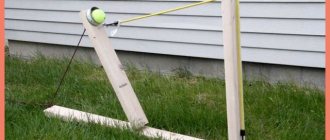
Summer, heat, beach, pond... As always, the standard program. I swam twice and lie there like a seal, bored. What can you do on the beach if you come without company? You can drive a radio-controlled boat! It’s fun for yourself and fun for the children.
I thought so last year, before the swimming season. It seemed like there was nothing to do there. I pulled out the drawings from the global network; they are presented below, just for information. Normal drawings are at the link, there is also an AutoCAD file from which I built my trough. (Blueprints).
Everything seems simple. Looking ahead, I’ll say that it took me a year and a half to make the boat))). It happened.
With the drawings it’s clear that we build what we like. But the biggest stumbling block may be the radio control equipment. You can, of course, take something like a radio control from a broken Chinese car, but then long-distance voyages are contraindicated for your ship. Firstly, the range will be small, and secondly, there will be no proportional control. If you can live with the latter, the former condemns you to having fun only in a small “puddle”. Well, as they say, something always gets in the way of a bad dancer.
I have radio equipment, proportional, 6-channel. Left over from unsuccessful attempts to launch a radio-controlled plane into the sky, nothing, I’ll also launch a plane someday. In the place with the equipment there were servos, batteries and a brushless motor with a control unit.
I decided to make the body using frame technology, as this is more familiar to me. You can read about other technologies on Google. I cut out the frames from scraps of 4 mm plywood (what I used):
I sanded it down to smooth edges using my sanding jig.
I made a slipway using a scrap from the kitchen countertop; I couldn’t do it without it.
And he started gluing it on the PVAshechka. PVA will not get wet unless you keep it under water for three days.
I decided to weigh in, for the sake of history:
Only 80 grams, “fluff”, for now.
Further more interesting. We need to cover the skeleton with something. And here I made my first mistake. If you go old school, then you need to sheathe it with either veneer or balsa. But times are different now, or rather the budget is different, I decided to save money. I decided to cover it with paper, in a couple of layers, followed by impregnation with epoxy resin.
It fits, in principle, nothing, but it soaks in very poorly! Office paper is not suitable for this at all!
With grief I pasted it in half. I glued it in two layers of paper, in the hope that everything would be saturated and become one. But no. Then I had to pierce the un-glued bubbles with a needle and fill them with cyan acrylic (superglue). I spent a lot of time on this (((
When all the glue had dried, I varnished the inside, after all, wood, paper, PVA... If next time I make a similar frame structure, I’ll probably try covering it with women’s tights impregnated with epoxy. Paper is a complete pain.
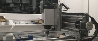
I finished the “trough” with grief, I started filling it. First I made a motor mount from a piece of brass. Why brass? for better heat removal from the engine. After all, my engine is an aircraft engine, designed for constant airflow from the propeller, but here there will be a closed box. But this didn’t seem enough to me, so I decided to add additional water cooling. I soldered a copper tube purchased from an auto parts store. I soldered on an electric stove, there was nothing else to heat it up with:
I made the motor mount removable for easy installation of the engine itself. The photo below shows fasteners made of epoxy. I did this in the following way: I pasted adhesive tape onto the motor mount and coated the adhesive tape with a thin layer of grease. Using plasticine, I secured the motor mount in the body at an angle; plasticine is also a formwork for resin. I inserted screws, also rubbed with grease, into the holes in the motor mount and tightened the nuts. I took furniture nuts, M4, with antennae. Then I filled it all with epoxy resin:
I forgot to say that I glued the motor mount together with the propeller shaft connected to the engine in order to maintain alignment. I ordered these items from China:
At first the coupling was simple, not cardan. But I drilled it out for the shaft of my engine and naturally the alignment disappeared. I had to buy an additional cardan. To interface through the coupling, the plastic thing at the end of the shaft had to be removed. The shaft and propeller are from a factory radio-controlled boat FT009.
sjigalov › Blog › DIY radio-controlled boat model. Part 1.
DISCLAIMER: EVERYTHING THAT IS DESCRIBED HERE, I DID MYSELF.
IN NO EVENT I AM SAYING THAT “THIS IS CORRECT, WE DO THIS.” THIS IS NOT A BOAT BUILDING INSTRUCTION. I DO NOT HAVE PROFESSIONAL TOOLS OR PROFESSIONAL WOOD WORKING SKILLS. I JUST LIKE WORKING WITH MY HANDS, GAINING EXPERIENCE, CREATING SOMETHING NEW. It all started in early February, when I accidentally came across parts for radio-controlled boats and catamarans on a well-known Chinese website. I was pleased with their low price, relative to other types of models (until that moment, the idea was to assemble a truggy or a monster based on a 1:10 scale short-course that had been lying on the balcony for a long time. But the prices for the parts were upsetting). And I caught fire. With my engineering thinking I figured out what parts were needed and what needed to be installed. I began to think about how to build a building. Since I have never been a shipbuilder, I started looking for hull drawings on the Internet. After spending several days searching, I was able to find them. If someone suddenly also wants to do something similar, the keywords are “Wasabi900e”.
900 is the length of the boat in mm. I also saw drawings for 1300 mm for a boat with an internal combustion engine.
I went to the printing center and printed out the drawings in A1 format. The original pdf file is in exactly this format. Everything was printed with millimeter accuracy. (My coursework has never been printed even with such accuracy, even if it was created according to size). We print 2 copies, or better yet 3, just in case. One copy of the main drawing for verification, the second for the stencil. Third - let it be.
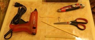
We go to a normal hardware store and look at the plywood. You need plywood, ideally 6mm. I couldn’t find one, but I found 4mm plywood, sawn into 50x50cm squares. Take 2 even(!) sheets. You will also need PVA carpentry glue (I already had universal glue, but later I bought a can of waterproof glue). We also look at a manual jigsaw and files for it.
If you have some kind of special tool for figure cutting, that’s generally great. You have to cut a lot and for a long time.
We are looking for a place to work, preferably a large table with good lighting, and glue the cut out parts from one of the drawings onto PVA. We clamp the plywood to the table with a clamp, and begin reciprocating movements with a jigsaw, and at the same time remembering the drunken worker at school.
I made a model at work. During one night shift I made the bow of the boat.
A small nuance. The central part, on which the 4mm plywood frames are attached, turned out, in my opinion, thin. It bent easily and was crooked. Glue it onto the plywood, pressing it well over the entire area, let it dry, and cut it out to the same shape as the one already cut out. We get 8mm thickness. Already more serious. We glue the frames, not forgetting that the grooves on them (in the center) are designed for 6mm plywood, they need to be expanded to 8mm.
On the next night shift I did the stern part. The drawing shows that it consists of a lower “board” 6 mm thick. We read the drawing and calculate the length - 441mm. I drew it on paper in advance, glued it to plywood, and sawed it out. We saw the remaining frames in the same way. We glue the keel and frames together, maintaining the dimensions. We do everything accurately so that it is not crooked.
The next step is gluing the body together. Docking occurs in the center. I took a board and put the stern and bow on it. Secure it with electrical tape. Under the nose part, approximately in the center, I placed electrical tape so that the nose was glued correctly and did not look down.
An important point: in the drawing, on the frames there are rectangular high “ears”. They are needed so that when the boat is turned upside down, it stands on them at the same height. In theory, it should be assembled this way.
In general, the skeleton is ready. The next point is the stringer(s) (I don’t know how to do it correctly) - long longitudinal sticks connecting the frames together. In the same hardware store I took a 10x10 mm bead, 150 cm long. According to the drawing they should be 6x6 mm. I clamp it in a vice and cut off the excess with a utility knife. You can use a plane, but I didn’t spend the extra money, and I have nowhere to find it. We glue them in starting from the stern to the bow, clamping them with a twisted pair wire. We’re not in a hurry to glue the nose yet, there’s a lot of work to do to make it look beautiful.
Radio controlled fishing boat
A radio-controlled fishing boat is a real find that any craftsman can build with his own hands. With its help, bait is delivered over long distances. You can buy such a product in a specialized store, but after several fishing trips it will break. Naturally, there are very high-quality models, but their cost is also impressive. It’s better to build a radio-controlled boat yourself, so you can be sure that it’s in good working order, and you’ll only need a few spare parts.
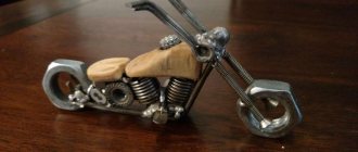
Radio controlled ship model from a toy car
The peculiarity of this homemade product is that the model is as close as possible to the real ship, that is, the proportions are respected. In total, the assembly process consists of several stages, this is the preparation of the necessary parts, the creation of the body, as well as the assembly and testing of the homemade product.
Ship manufacturing process:
Step one. We obtain the necessary elements
First you need to disassemble the machine and get all the necessary elements. The ship will need a rear wheel drive, an electronic part (radio control), a steering gear, and a compartment in which the batteries are installed. The machine is disassembled using a screwdriver, first the body is removed, and then the radio module and other elements are unscrewed. When disassembling, you need to use a camera or mark the wires. Otherwise there may be difficulties later. You need to remember how the wires from the board to the motor, power supply, and antenna are connected. Often toys use very thin wires. It is advisable to remove them and solder them with a larger cross-section.
The engine compartment also needs to be cut out from the bottom; the author used a hacksaw blade for this purpose. When all the elements are removed, it is advisable to check their functionality.
Step two. Ship hull
The body is cut out in one piece, using a piece of polystyrene foam 60 mm thick. First you need to make a paper pattern with the contours of the boat deck. The dimensions of the pattern are 400 × 80 mm. Next, the contours are transferred to polystyrene foam and cut out using a jigsaw at an angle or straight. The aft cut must be made to match the diameter of the propeller.
Step three. Installing the necessary elements into the case
To install the shaft, they need to carefully push the hole into the motor. The shaft is attached to the gearbox axis using a piece of plastic tube of suitable diameter. It can be glued or tied with copper wire. After this, the motor needs to be started, if it works without effort, then you can install the screw on the shaft.
The engine, as well as the steering gear, are mounted on hot glue.
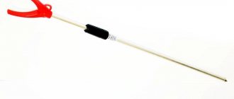
As for the ship's superstructure, it is made of foam plastic cut into thin pieces. The sheets are connected to each other using hot-melt adhesive. Inside the add-on there is a radio control board. As for the antenna, it is made from a piece of enameled copper wire, which is mounted on a mast made from a barbecue skewer.
Step four. Ship testing
Now you can start testing. It is quite possible that the boat will float crookedly; it can be easily centered using the keel. As for the control range, it is as much as 100 meters, which is more than enough for such a model. The ship can be modified by changing the size and pitch of the propeller.
Source
Product manufacturing technique
It’s not difficult to make a radio-controlled boat for fishing with your own hands, you just need to follow the sequence of work:
- Manufacturing of the body. If plywood is used, you will additionally have to line it with fiberglass and coat it with epoxy resin. This will help protect the material from rotting. It is necessary to cut plywood or fiberglass according to a previously drawn or downloaded diagram. In order to seal all seams, polyurethane foam is required.
- Installation of the power frame. Thanks to it, the load on the hull is distributed evenly, and it remains afloat. The bow of the boat can be filled with foam, which guarantees its unsinkability.
- Installation of a pipe with a screw. The blades of the driving component remain inside the housing, so they will not get tangled in weeds, injure fish, or snag on snags. The pipe opening must additionally be covered with a grill.
- Arrangement of the electronic part. Now the engine, stern tube, shaft with coupling and propeller are installed. In order for a fishing boat to sail in a given direction and turn, it must be equipped with regulators.
- Installation of servomotors for opening containers with bait. They must be located in housings that do not allow dust and moisture to enter.
- Installation of batteries.
To control the product, it is better to choose a five-channel radio system that is installed on toys.
Theory
The submarine model is built according to the same principles as the real one. In a waterproof housing, inside of which all controls and electronics are hidden. On the outside, it is surrounded by a “light” permeable body, which serves as a streamliner and a beautiful appearance. Our model will consist only of a durable body.
At speed, the submarine can dive using depth rudders, and in a static position only with the help of a ballast tank. How it works? When floating on the surface, the mass of the boat is slightly less than the mass of the volume of displaced water (Archimedes' law). Those. if the boat has a volume of 3 liters, then its mass should be slightly less than 3 kg.
Theoretical calculations of the immersion of a submarine model.
There are 3 main problems during construction. They are completely independent and can be solved separately.
Operating procedure
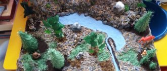
1. Assembling the hull of a catamaran boat. - draw a sketch of the boat:
- Having made the markings, cut along the red lines; — bend along thin lines and bend angles: 1 – tilt of the bow of the boat; 2 — raising the bow of the boat; 3 – lifting the stern; 4 – tilt of the stern; - fasten the bent parts with paper clips; - glue the paper with any glue, after which the shape of the boat will be ready; — measure the displacement of the boat; — we will make the form rigid, for which we will wrap the body inside with cellophane and fill it with filler; — epoxy mass is applied to the resulting blank, wrapped in fiberglass; — after hardening, the body can be easily removed; — a second hull is also being made for the catamaran.
Ballast tank
This is usually the most difficult part of a submarine. But we will do it simply - we will use a micropump. More precisely, a peristaltic micropump - it holds the pressure itself and does not require additional valves. The pump itself is capable of developing a pressure of 1 atmosphere, which means it can pump a tank at a depth of up to 10 meters. The pump is controlled in the same way as a conventional electric motor - a speed controller or servo with micro switches.
The original silicone tube in the pump was 2.54mm, changed to 46mm. As a result, throughput increased by 1.5 times. The motor is designed for 6 volts, I supply 12. The motor heats up a little, but not critically. The final speed is 100ml in 20 seconds.
Cover (deck) of the boat and controls on it
The material for the cover was fiberglass laminate 2 mm thick. I attached the hull of the fishing boat to a sheet of fiberglass laminate, traced the outline with a marker, and cut out the desired shape with a jigsaw.
The weight of the lid was 590 grams. For such rigidity this is quite a normal result.
Next, I placed the main power switch on the lid (it comes complete with a rubber cap),
I placed the power regulators and the toggle switch for the flashlight in a powder container, which I attached with “liquid nails” glue for complete waterproofing.
For the receiver phone and voltmeters, I used an external junction box. It also houses the battery contacts for charging the battery. On the back side there is a connector for unloading.
Battery and charger
An inexpensive computerized charger allows you to charge directly from a car battery. Costs 680 rubles.
We take LiPo batteries - these are the best that can be found on the model market.
We put 2 batteries in the cart for 380 rubles, the total price became 5710.
You can not skimp and take the top ones, 2 pieces for 1150 rubles and the total price will be 8150 rubles, but since fishing is not every day, it is cheaper to change cheap ones every 3-4 years.
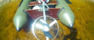
And here is a video of how a homemade boat sails to deliver bait across the lake.
I’ll talk about connecting all the electronics in a separate article, but for now, let’s summarize.
Electrical diagram
Everyone stays where they are and no one runs away. There is nothing to be afraid of. Below is a complete wiring diagram for a fishing boat. The diagram is large because it is detailed, but now everything will become clear.
Dotted lines highlight individual blocks. You may not use some of them at all, or replace some with an inexpensive purchased analogue. Just one circuit may seem complicated to you, but you don’t even need to understand it, and if you want, you can solder even what you don’t understand.
Layout
The boat measures 60cm in length and 7.5cm in diameter. Inner diameter 71mm. The plugs extend 2.5cm each.
Inside the case is divided into “compartments”.
The tank must be in the middle so that the boat sinks horizontally (there is no trim).
The fastening elements are made of 5mm thick porous PVC sheet. Then they are tightened on iron pins located along the body. The rear plug should also be secured to studs to ensure the rigidity of the assembly with the motor and steering rods.
Initially, stroke controllers were used to control the motor and pump. But their reverse is much slower than forward rotation, which is not convenient for the pump. During testing, I did not install a separate UBEC power circuit and used the built-in 1 amp BEC. Because I received a defective servo that jammed, at that moment the current jumped and burned the entire regulator.
The 550 series motor is redundant for a model of this size; you can get a smaller one. It is attached with screws to a special bracket to the rear plug. Connection to the shaft through a brass coupling.
It is also worth installing Fail-safe modules on the pump and motor channels. The engine is set to turn off, and the pump is set to purge the tank.
Programming Arduino microcontrollers
Arduino, if anyone doesn’t know, is a microcontroller for the general public. Very accessible and simple. Roughly speaking: I connected it to the computer via USB, loaded it with a sketch (a program that says what the microcontroller will do) and everything is ready. I will not describe the process of installing drivers and downloading programs. Everything can be found on the Arduino website.
If you have any questions, the network is full of detailed descriptions of this process.
My bait boat uses two Arduino boards: one UNO and one NANO.
For Uno, in addition to the sketch, you will need libraries.
How much does it cost to build a boat for delivering bait?
So, the final price of the equipment is 5,870 rubles.
Is it a lot or a little?
Bait delivery boats sold in stores cost about 30,000 rubles. At the same time, they use brushed motors (20-30 trips on water and you need to change the motor brushes or replace the engines) and outdated equipment on the FM band (prone to interference, you can lose control of the boat).
Usually, after six months of using a purchased boat for delivering bait, they begin to remodel it - change the engines to a brushless version (see the price above in the article), along with the engine, the regulators will have to be changed to a brushless version.
The transmitter and receiver also require replacement - they install Turnigy 9x, it operates in the noise-immune range of 2.4 gigahertz.
A lead-acid battery loses its characteristics over the winter, unless, of course, it is discharged and charged a couple of times a month - but who does that? So, on the advice of experienced people, they change the battery to LiPo, they are not susceptible to such phenomena, and buy a charger for them.
In fact, all that remains of the purchased boat is the hull and a pair of servos for opening hatches with bait.
Are you ready to pay 30 thousand rubles for a pair of servos costing less than 300 rubles and a housing that can be made in a couple of weekends?
So it turns out that making a boat for delivering bait with your own hands is much more profitable!
To catch up - you can buy a cheap toy boat for 2-3 tr, add floats on the sides to it (made from polystyrene foam and covered with tulle on a scuba tank, fiberglass on a plastic one, or painted with auto enamel) and drive it around. You can open the feeder compartments by pulling a strong nick or fishing line from the ground - this is the cheapest option!