© 2015 Vasili-photo.com
I bring to your attention a translation of the article “An Interesting Distance Meter” by Edward J. Ramaley, published in the magazine “American Photography” for February 1939. The article describes how an original optical rangefinder can be made from a piece of cardboard. Of course, these days most cameras are equipped not only with a rangefinder, but with full-fledged autofocus, which greatly reduces the practical significance of the primitive device described in the article. Nevertheless, the homemade device remains a very entertaining toy, with wide entertainment and educational potential and allows you to take a slightly new look at the work of your own eyes.
The style of presentation may seem somewhat confusing in places, but this is how it is in the original - I tried to translate as close to the text as possible.
The purpose of a rangefinder in photography is to enable the photographer to focus the lens on a subject without having to measure the distance separating them with a ruler or tape measure. Focusing is accomplished by changing the distance between the lens and the image in accordance with the distance from the lens to the subject. Careful focusing is especially necessary when the lens aperture diameter is large enough compared to its focal length. In general, any lens used at its maximum aperture needs to be focused extremely carefully when shooting close subjects.
An optical rangefinder collects light through two receiving systems, which are coupled in such a way that the two images they generate can be combined into one. Proper adjustment of this device can be tied to the position of the pointer on the scale, or directly to the focusing of the photographic lens. Based on this, it might seem logical to use our own pair of eyes directly as an optical rangefinder, which can be implemented in several ways. One is to use an individually calibrated scale held at arm's length and observed to measure the convergence of the eyes looking at an object.
Rangefinder calibration
Cut a triangle from cardboard with a base of three inches and a height of eight inches. From a window or other light source, set the shortest distance indicated on the focusing scale of your camera, and the measurer stands at this point facing the light. The triangle should be held opposite the window in front of the eyes at arm's length, using natural muscle effort, which could be reproduced at will. By focusing your eyes on the window, you will see that the triangle appears double, since each eye is looking at it from its own point of view. While still maintaining focus on the window, you can apply a straight ruler across the triangle, parallel to its base, so that it intersects the edges of each of the two imaginary triangles at the point of their mutual intersection. Finally, a line is drawn along the ruler. This completes the calibration for this distance.
The full focusing scale of your camera is applied to the cardboard triangle in exactly the same way: stepping back from the window at the appropriate distance, determine where the two imaginary triangles intersect and draw a horizontal line through this intersection. The rangefinder's accuracy decreases as the distance increases, but so does the need for critical focus. The accompanying drawings show what the completed rangefinder looks like and how it appears when the eye is focused on a point behind it.
| Rice. 1 Rangefinder (for the author’s eyes and hands). | Rice. 2 View of the rangefinder when the eyes are focused on the object behind it. |
Homemade electronic altimeter-variometer-tweeter (3.3-volt version)
Significantly reworked my project of an altimeter-variometer with sound and light signals.
Therefore, I decided to write the material as a separate article. As before, there are parachute and paragliding versions of the firmware.
Component connection diagram
Parachute works both with and without a display. Paragliding - no display yet. Used inexpensive and readily available components.
What's new? What did you have to give up?
In the new version of the device: - power supply from one 3.7V LiPo cell (instead of the 9 volt Krona element); — Arduino ProMini 3.3V 8 MHz board (instead of the 5 volt Arduino Nano V3); — liquid crystal display Nokia 5110 (instead of the LCD display 1602); — charge-discharge board of LiPo element with micro-USB connector.
I use the same Gy-68 (BMP180) sensor.
The device has been transformed and become more compact. The size of a small alarm clock.
And if you remove the display, it will fit into a protective helmet! I'm thinking of shrink-wrapping it, maybe even transparent. Let the “high-tech” content be visible.
On the left is a battery with a charge-discharge controller, on the right is a board with a sensor and a speaker from a cell phone. I connected a 120 ohm resistance in series with the speaker. The volume is quite acceptable if placed in a helmet.
I drew a wire in the form of a “tail” where you can solder any switch your heart desires. I used a regular computer jumper.
The algorithm of work is still the same. Both parachute and paragliding versions.
Without a display with an element with a capacity of 100 mA, AltVar V2 worked continuously for more than 10 hours.
With a connected display (the backlight was turned on) and a 200 mA element - more than 7 hours. Without display backlight - more than 20 hours.
I rode a device with parachute firmware on an elevator - it works just like my previous version.
Can be used as a regular high-precision altimeter-variometer.
Information output format:
A: 15 (altitude in meters) —v— (sign of descent, in case of climb +++^+++) V: 0.0 — (vertical speed in m/sec)
Paragliding firmware - no display yet. I found some sound glitches in the display version. I haven’t figured out why yet... That’s why I’m not publishing the sketch.
The paraglider version without display works well and this firmware can be used. The sketch I used as the basis for my project also works. My deep gratitude to its author!
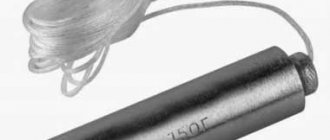
I replaced the piezo tweeter, as I already indicated, with a speaker from a cell phone, connecting a 47 Ohm resistance to it in series. It sounds quite loud and clear. I installed the speaker like this
All connections of components are indicated in the “header” of the sketch. Here is an example of connecting a display (taken from this very “header”):
Display NOKIA 5110 (blue)
Display 5110 Pro Mini Serial clock out (SCLK) 3 Serial data out (DIN) 4 Data/Command select (D/C) 5 LCD chip select (CS) 6 LCD reset (RST) 7 VCC (maximum 3.3 volts) VCC BL (backlight) VCC (for red display - GND) GND GND
The compiler is the same - 1.0.6
I flashed it using a regular TTL-UART USB adapter CH340G. He is the most patient, he will not reset the Arduino. Therefore, after compilation, I pressed the RESET button myself.
All firmwares send altitude, vertical speed and pressure data to the COM port. True, when working in this mode, the system can identify it as some kind of Microsoft gadget, and not working correctly.
In general, it turned out quite simple and quite budget-friendly.
I thank everyone who responded to my previous article on this topic. I took some of your comments into account when creating a new modification of my device.
Source
How to use a rangefinder
In practical use, the scale is held vertically at arm's length while the eyes are focused on a significant part of the scene. The thumbnail slides up the scale until the two triangles appear to intersect, at which point the eye can move to the triangle to see which line the nail marks and focus the camera accordingly. It would seem that nothing could be simpler, but there are some annoying obstacles that should not be forgotten.
Our eyes deceive us. Sometimes we think we are looking exactly at an object, but in reality our eyes are focused on a point in the air. The remedy for this is to take several readings quickly enough, without giving your eyes time to tire or hesitate. Repeat until consistent results are obtained. It should also be remembered that the pupil of the eye is not a point, and its size in bright light is not the same as in dim light. As a result, there is a certain lack of precision at the far end of the scale, and when reading the scale you have to use approximately the same brightness as when calibrating. This effect is reduced if you perform the calibration in moderately bright light and look at the light of the same intensity immediately before reading.
The mathematical relationship and rationale for this device is shown in Fig. 3, and, as can be seen, the distance between the eyes is quite significant for large distances. The idea is that if the scale is calibrated in a bright room and is also used in a bright room, the distance between the eyes does not change. Meanwhile, in dark places the eye pupil dilates, thus exaggerating some values and downplaying others.
Another source of instability, namely, the difficulty of keeping the scale always at the same distance, is very easily overcome by very little practice, by the use of a natural position and comfortable muscular effort. Errors in holding the triangle are especially significant at close ranges.
This device is not suitable for commercial production, since it must fit a specific pair of eyes and a specific hand. It costs nothing and can be made in half an hour, but when used with due care, it turns a pair of keen eyes into an excellent rangefinder that requires no excuse. Continued use of this device in photographing children at play at close range and with the aperture wide open produced many satisfactory negatives and demonstrated the usefulness of the device.
Fig. 3 Curves showing the dependence of the length of marks on the scale on the distance to the object for an arm length of 27 inches and various distances between the eyes. CD is the length of the line on the scale in inches. BE is the distance from the eyes to the object in feet. AB is the distance between the eyes in inches.
***
Post scriptum
If you found the article useful and informative, you can kindly support the project by making a contribution to its development. If you didn’t like the article, but you have thoughts on how to make it better, your criticism will be accepted with no less gratitude.
Please remember that this article is subject to copyright. Reprinting and quoting are permissible provided there is a valid link to the source, and the text used must not be distorted or modified in any way.
Source
Translator's afterword
One cannot help but pay tribute to the author’s ingenuity, although the literary side of the article, of course, leaves much to be desired.
It is not entirely clear to me how changing pupil size can affect the distance between the pupils. Obviously, the author does not mean the distance between the centers of the pupils, but rather the distance between their medial edges. In my opinion this is not entirely correct. In the end, the optical axis of the eye passes through the center of the pupil, and therefore for our purposes it is the distance between the centers of the pupils that is important, which does not depend on their diameter. True, when the pupil dilates (mydriasis), the depth of sharply imaged space decreases, as a result of which out-of-focus objects (including the double triangle of the rangefinder) will look somewhat blurrier. This slightly reduces the accuracy of the measurement, but not so much that this fact is worth paying special attention to.
| Fig.4 This is what a metric rangefinder looks like. |
The precision of rangefinder calibration empirically, i.e. literally by eye, also raises certain doubts in me. The measurement method is too inaccurate (especially for long distances) to be used when marking a reference scale. In my opinion, it is better to calculate the location of the horizontal marks on the rangefinder scale. I even came up with an algorithm that can make this task easier. All you need is to ask someone to measure the distance between the centers of your pupils (with your eyes looking into the distance), as well as the distance from the eyes to the rangefinder scale held at arm's length, then insert the resulting numbers into the appropriate cells of the form and press Click the “Build table” button. For each distance, you will receive the height of the corresponding horizontal mark, counting from the base of the triangle, as well as its length (segment CD in Figure 3). All measurements are, of course, metric.
Homemade electronic altimeter-variometer with sound and light warning signals
Can be used in aviation sports as an additional means of ensuring safety when:
— performing parachute jumps; — paragliding; — flights on ultra-light aircraft
Advantages of this solution:
— low price of components (1200-1500 rubles at retail, much cheaper when purchased in online stores in China); — ease of assembly (can be assembled in an evening, on a breadboard it can be done in half an hour); — high accuracy of height measurement; — compactness and light weight of the device; — open program code (you can make changes, change the threshold settings for the device’s response); — can be used as a module for measuring atmospheric pressure (relative altitude, vertical speed and atmospheric pressure are constantly transmitted via the COM port). — Powered both from an autonomous DC source (6-20V) and via a Mini-B USB cord.
Prehistory of creation:
AltVar+, as I called it, was created on the basis of this project in the form of a variometer - a tweeter. The prototype was assembled on a breadboard. There were only two significant components on it: - Arduino Nano V3 microcontroller board - Gy-68 pressure sensor
The device reacted with a squeak to ascents and descents, but there was no indication. Therefore, the program had to be modified.
Now the board transmitted altitude and vertical speed values to the computer’s COM port. I wanted more autonomy and I added a 4-digit 7-segment display, enclosed the board with the sensor in a homemade case, and built a battery into it. The relative height value was displayed on the display. Now the device could be used both to measure relative altitude and as a high-precision barometer.
Displayed altitude and vertical speed data on an LCD display 1602 (16 characters, 2 lines).
So the device told me what to call it.
AltVar+ regularly showed the slightest changes in altitude and vertical speed.
To output a sound signal, I left part of the code of the original project. I tested it for days on end. AltVar+ worked reliably. Or rather, there was not a single failure! In the autonomous version (with a 200mA 9V element of the “Krona” type) it worked for 8 hours without a break and turned off due to power.
The program code for the microcontroller was created using the Arduino 1.0.6 compiler. In several stages, gradually adding functionality.
The program algorithm works simply and straightforwardly:
— altitude and vertical speed values are constantly displayed on the LCD display; — the obtained values of altitude and vertical speed are compared with threshold values set by the user, and based on the results of this check, sound and light signals are issued
When the device is turned on, the threshold values of altitudes and speeds specified by the user are displayed. At first glance, it’s cumbersome, but it’s informative!
Changes can be made by changing values in the program and loaded into the microcontroller after compilation. The algorithm of the program is designed in such a way that before each jump you need to initialize AltVar+ (turn it off or on). We kind of “cock” it. What is it for?
After cocking we have:
— the most accurate value of the zero height of the site; — the values of the variables responsible for the number of sound signals take their original values; - save battery power
The program, as I already indicated, was created for parachutists. The “Chinese style” of writing will allow even a beginner to understand it. Everything is simple and unambiguous, it seems to me. I see no obstacles to adapting it for a paraglider (paramotor) and SLA.
I provided as comprehensive comments as possible to the program lines. The “header” indicates the necessary components, mutual connections of elements, and resistor values. You can open it in a text editor or compiler and look.
In this version of the program, three heights are specified for high vertical speed:
— Ready – 1 beep (set to 1000 m); — notifications (Alert) – 3 sound signals (800 m); — alarm (Alarm) – continuous sound signal (600 m)
The signal will be removed when the vertical speed decreases to the threshold (set to 25 m/s)
Introduced two more informational sound signals: - upon reaching a certain altitude (Climb) on board the aircraft (300 m at a vertical speed of more than +1 m/s); — upon reaching a certain altitude (Baza) when descending by parachute (200 m at a vertical speed of more than –1 m/s, here the triggering altitude was limited to a minimum of 25 meters because on the ground after turning on AltVar+, various unexpected pressure surges are possible, which will cause signal);
In addition, all sound signals were duplicated by LEDs.
By connecting AltVar+ via the COM port, you can use some third-party device to record the vertical flight profile. At first I used this feature to debug the program and decided to leave it. To obtain an accurate value of atmospheric pressure, it is necessary to make a correction to the code variable reserved for this purpose. Then there will be extremely accurate readings of atmospheric pressure. Otherwise, the device, even without this correction, provides measurements of height and vertical speed with fairly high accuracy.
The functionality can be further expanded.
For example: - measuring the voltage of the power source; — record data on emergency modes from the log (a sort of “virtual “SyPReS”); — set a vibrate alert; - etc. and so on. But for now I settled on this set of signals.
Assembling prototypes for field testing.
Soldered all AltVar+ components on breadboards
I placed the board under the LCD screen, which is certainly not a dogma. Can be placed next to it. The device will become flatter, but wider.
I made a case from 4 mm plastic for the device itself and for the battery (9V “Crown”). I treated the joints and edges and blew it out from an aerosol can. What can I say... “Kondovo” turned out.
Perhaps not compact enough. Actually, you could use a small soap dish with cut holes for the display, switch and sound jack. But what happened is what happened.
At least there is something to test.
The stages of this testing are as follows:
— stability of operation in a static state; — checking autonomy; — “elevator test” with greatly reduced threshold values of heights and vertical speeds; — parachute jumps with elevated (altitude) thresholds for the device’s response
Video 2 “elevator test”, significant up to 1:45, then I opened the box and the camera started to crackle, OK
I think it was a success.
The following were asked:
When passing all heights, AltVar+ “bleated” a specified number of times. And the LED blinked. After the vertical speed decreased below the threshold value, the alarm signal was removed. That is, he behaved quite predictably, as I had planned.
We will test it further.
Almost anyone can assemble such a device if desired and, using open source code, program it to suit their needs.
Let me summarize
- Arduino Nano V3 microcontroller board - Gy-68 pressure sensor - LCD - 1602 display - 3.5 mm audio jack; — resistors 4k7, 1K, 330 ohm; — 5V LED; — battery “Krona”; - switch; - breadboard with conductors
- Arduino 1.0.6., connecting the libraries of the port, sensor, display and speaker - sketch (program that is loaded into the microcontroller)
PS I designed a board to make AltVar+ easier to assemble. But I haven’t made it yet.
It beeps like the original project, indicates altitude and vertical speed. The LED lights up when the temperature drops, even minimally.
AltVar+ can also be used as a green LED flashlight