I recently bought a plot of land in the countryside and am setting up a dacha there. I’ve already finished everything, I come, rest and leave, I often go there on weekends. The other day I came up with a brilliant idea to construct a homemade steam engine so that it would not be so boring there, because it would be possible to make a model of a train or how to use it for household needs, but most likely I will use it just for fun. I have already done it and then I want to tell you how to make a steam engine with your own hands.
Source ytimg.com
Real prospects for creating a perpetual motion machine using magnets
Opponents of the theory of creating a perpetual motion machine say that it is impossible to violate the law of conservation of energy. Indeed, there are absolutely no prerequisites for obtaining energy from nothing. On the other hand, a magnetic field is not emptiness at all, but a special type of matter, the density of which can reach 280 kJ/m³. It is this value that is the potential energy that a perpetual motion machine on permanent magnets can theoretically use. Despite the lack of ready-made samples in the public domain, numerous patents indicate the possibility of the existence of such devices, as well as the fact of the presence of promising developments that have remained classified since Soviet times.
Norwegian artist Reidar Finsrud created his own version of a perpetual motion machine using magnets
Famous physicists and scientists contributed to the creation of such electric generators: Nikola Tesla, Minato, Vasily Shkondin, Howard Johnson and Nikolai Lazarev. It should be noted right away that engines created with the help of magnets are called “eternal” conventionally - the magnet loses its properties after a couple of hundred years, and along with it the generator will stop working.
Making an inductor
2 holes are made in the plywood structure; subsequently, the electric motor coil is secured here with bolts. Such supports perform the following functions:
- anchor support;
- performing the function of an electrical wire.
After connecting the plates, the structure should be pressed with bolts. To ensure that the anchor is secured in a vertical position, a frame is made of a metal bracket. Three holes are drilled in its design: one of them is equal in size to the axis, and two are equal to the diameter of the screws.
Myth or reality?
Perpetual motion is familiar to almost everyone from school, only in physics lessons it was clearly stated that it is impossible to achieve practical implementation due to friction forces in moving elements. Among the modern developments of magnetic motors, self-supporting models are presented, in which the magnetic flux independently creates a rotational force and continues to support itself throughout the entire operation process. But the main stumbling block is the efficiency of any motor, including magnetic, since it never reaches 100%. Over time, the engine will still stop.
Therefore, all practical models require repeated intervention after a certain time or some third-party elements operating from an independent power source. The most likely option for fuel-free engines and generators is a magnetic machine. In which the main driving force will be the magnetic interaction between permanent magnets, electromagnetic fields or ferromagnetic materials.
A current example of implementation is decorative decorations made in the form of constantly moving balls, frames or other structures. But for them to work, it is necessary to use batteries that supply direct current to the electromagnets. Therefore, next we will consider the principle of action that gives the most encouraging expectations.
Single cylinder electric motor
If the previous version did not perform any useful work due to its design features, then this model will be a little more complicated, but will find practical application in your home. To make it, you will need a 20 ml disposable syringe, copper wire for winding the coil (in this example, 0.45 mm in diameter is used), larger diameter copper wire for the crankshaft and connecting rod (2.5 mm), permanent magnets, wooden strips for the frame and structural elements, DC power supply.
Additional tools you will need are a glue gun, a hacksaw, a stationery knife, and pliers.
The manufacturing process of an electric motor is as follows:
- Using a hacksaw or utility knife, cut the syringe to create a plastic tube.
- Wind a thin copper wire around a plastic tube and secure its ends with glue; this will be the stator winding.
Rice. 5: Wind the wire around the syringe - Remove the insulation from thick wire using a utility knife. Cut two pieces of wire.
- Bend these pieces of wire into a crankshaft and connecting rod for an electric motor, as shown in the figure below. Rice. 6: Bend the crankshaft and connecting rod
- Place the connecting rod ring on the crankshaft to ensure a tight fit; you can put a piece of insulation under the ring. Rice. 7: Place the connecting rod onto the crankshaft
- From wooden dies, make two stands for the shaft, a wooden base and an eyelet for neodymium magnets.
- Glue the neodymium magnets together and glue the eyelet to them using a glue gun.
- Secure the second ring of the connecting rod in the eye using a cotter pin made of copper wire.
Rice. 8: fix the second ring of the connecting rod - Insert the shaft into wooden posts and put on bushings to limit movement; make them from pieces of original wire insulation.
- Glue the stator with the winding, the struts with the connecting rod on a wooden base; in addition to wood, you can use other dielectric material. Rice. 9: Glue the struts and stator
- Using flathead screws, secure the terminals to the wooden base. The two contacts must be long enough to touch the motor shaft - one curved, the other straight.
Rice. 10: Shaft touch points - Place a flywheel on the shaft on one side to stabilize rotation, and an impeller for the fan on the other.
- Solder one terminal of the motor winding to the knee contact, and the second to a separate terminal.
Rice. 11: Solder the winding leads - Connect the electric motor to the battery using alligator clips.
The single-cylinder electric motor is ready for operation - just connect power to its terminals for operation and spin the flywheel if it is in a position from which it cannot start.
Rice. 12: connect power
To stop the fan rotating, turn off the electric motor by removing the crocodile clip from at least one of the contacts.
Operating principle of the gravity device
During rotation, the engine will be subject to frictional forces, air resistance and other factors. As an example, a structure consisting of sealed S-shaped elements is considered. Each of them is filled with water and air in a 1:1 ratio. With each cycle of rotation of this structure, a small amount of energy will flow from the gravitational field. If the total amount of energy received from each element during the entire cycle exceeds the engine’s costs of overcoming friction and other factors, then the device will gradually begin to gain momentum. This will happen until gravitational effects cease to appear under the influence of centrifugal forces. Thus, a gravitational engine initially requires good spin-up, like other driving devices. A typical example is the automobile internal combustion engine, which was started in different ways: at first - with a special handle, and in modern conditions - with a starter. In this case, the power of the gravitational engine depends on the number of S-shaped elements.
The operation of a water engine occurs according to a certain pattern. First, you need to unscrew it well in a clockwise direction. After this, the area with water will be in a horizontal position, and the water will flow from one elbow to the other. The area freed from water will begin to rotate rapidly.
At the same time, the water moves in the horizontal direction, crossing the lines of force of the gravitational field. Consequently, without doing any work, it will fill the empty section of the pipe, which, under the influence of gravity, will begin to move downward. Thus, due to constant overflow, the engine will rotate. Movement control is carried out due to the moment of inertia inherent in the S-shaped pipe.
As a result of rotation, the motor gradually reaches a certain speed, after which the energy received by the parts is transferred to the load. In addition to connecting to any useful device, it is spent on overcoming air resistance and friction. Having reached a certain rotation speed, the engine will begin to operate in automatic oscillation mode. Gravity will prevent the rotation speed from decreasing, and it will also limit it due to the concentration of water at the outer end of the pipe, which is why the gravitational effect is significantly reduced.
In order to improve the dynamic properties of the engine, sealed elastic containers filled with a small amount of air should be placed at both ends of the rotating element. During rotation, they will perform the function of a kind of spring in relation to the water.
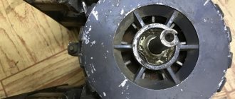
The process of converting into a generator
The sequence of actions is as follows:
- The rotor is removed after removing the cover;
- The same stator windings remain; rewinding is not carried out;
- In order for it to become prefabricated, as opposed to its original solid state, it must be ground down to a predetermined size;
- A steel cup five millimeters thick is pressed onto the rotor;
- One of the most difficult operations is marking, which is carried out in order to glue the magnetic elements to the rotor according to the template. The dimension is individually selected for each engine unit;
- Magnetic elements made of neodymium are glued with superglue and additionally reinforced with a nylon filament mesh;
- Everything is wrapped with tape and formwork is carried out to seal it, and then filled with epoxy;
- Flowing down, the resin hardens, after which the tape must be removed;
- The rotor is driven into the generator part with all precautions so that the rotor “stands up” and does not “fly” into the stator due to the force of the magnets;
- The structure is assembled and closed with a lid;
- The functionality is checked using a drill.
The most famous analogues of perpetual motion magnets
Numerous enthusiasts are trying to create a perpetual motion machine using magnets with their own hands according to a scheme in which rotational motion is ensured by the interaction of magnetic fields. As you know, poles of the same name repel each other. It is this effect that underlies almost all such developments. Proper use of the energy of repulsion of like poles of a magnet and attraction of unlike poles in a closed loop allows for long-term non-stop rotation of the installation without the application of external force.
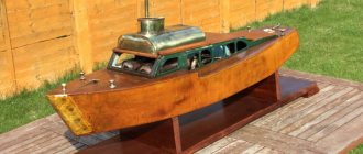
A little about the steam engine and its operating principle
A steam engine/steam engine is an external combustion heat engine that uses and converts the energy of water vapor into rotational-translational mechanical work of a piston and shaft.
A steam engine can be considered any external combustion engine that converts steam energy into mechanical work.
The principle of operation of a steam engine is very simple: by burning fuel, water is heated and turned into water vapor, which in various ways sets the piston in motion, the piston rotates the shaft, and at the output we have mechanical work from the shaft.
Hanging model
To make a perpetual motion machine with neodymium magnets with your own hands, you need to use two disks. It is best to choose a copper casing for them. In this case, the edges must be carefully sharpened. Next, it is important to connect the contacts. There should be four magnets in total on the outside of the disk. The dielectric layer must run along the fairing. To eliminate the possibility of negative energy appearing, inertial converters are used.
In this case, positively charged ions are required to move along the casing. For some, the problem is often a small cold sphere. In such a situation, fairly powerful magnets should be used. Ultimately, the heated agent must exit through the fairing. The suspension is installed between the disks at a short distance. The source of self-charging in the device is the converter.
General structure and principle of operation
Work on the so-called perpetual motion machine has been going on for a very long time and does not stop at the present time. In modern conditions, this issue is becoming increasingly relevant, especially in the context of the looming energy crisis. Therefore, one of the options for solving this problem is a free energy engine on neodymium magnets, the action of which is based on the energy of the magnetic field. Creating a working circuit for such an engine will make it possible to obtain electrical, mechanical and other types of energy without any restrictions.
Currently, work on creating an engine is at the stage of theoretical research, but in practice only a few positive results have been obtained, allowing us to study in more detail the principle of operation of these devices.
The design of magnetic motors is completely different from conventional electric motors, which use electric current as the main driving force. The operation of this circuit is based on the energy of permanent magnets, which sets the entire mechanism in motion. The entire unit consists of three components: the motor itself, a stator with an electromagnet and a rotor with a permanent magnet installed.
An electromechanical generator is installed on the same shaft as the engine. Additionally, a static electromagnet, which is a ring magnetic circuit, is installed on the entire unit. An arc or segment is cut out of it and an inductor is installed. An electronic commutator is connected to this coil to regulate the reverse current and other operating processes.
The very first motor designs were made with metal parts that had to be influenced by a magnet. However, to return such a part to its original position, the same amount of energy is expended. That is, theoretically, the use of such a motor is impractical, so this problem was solved by using a copper conductor through which an electric current was passed. As a result, an attraction of this conductor to the magnet occurs. When the current is turned off, the interaction between the magnet and the conductor also stops.
It has been established that the force of a magnet is directly proportional to its power. Thus, a constant electric current and an increase in the strength of the magnet increase the effect of this force on the conductor. The increased force helps produce a current that will then be applied to and through the conductor. As a result, a kind of perpetual motion machine using neodymium magnets is obtained.
This principle was the basis for an improved neodymium magnet motor. To start it, an inductive coil is used, into which an electric current is supplied. The poles of the permanent magnet must be perpendicular to the gap cut into the electromagnet. Under the influence of polarity, a permanent magnet mounted on the rotor begins to rotate. The attraction of its poles to the electromagnetic poles, which have the opposite meaning, begins.
When the opposite poles coincide, the current in the coil turns off. Under its own weight, the rotor, together with the permanent magnet, passes this coincidence point by inertia. At the same time, a change in the direction of the current occurs in the coil, and with the onset of the next operating cycle, the poles of the magnets become identical. This leads to their repulsion from each other and additional acceleration of the rotor.
Anti-gravity magnetic Lorentz motor
You can make a Lorenz engine yourself using simple materials.
If you want to assemble a perpetual motion machine using magnets with your own hands, then pay attention to Lorenz’s developments. The anti-gravity magnetic engine of his authorship is considered the simplest to implement. This device is based on the use of two disks with different charges. They are placed halfway into a hemispherical magnetic shield made of superconductor, which completely pushes out magnetic fields. Such a device is necessary to isolate the disk halves from the external magnetic field. This engine is started by forcing the disks to rotate towards each other. In fact, the disks in the resulting system are a pair of half-turns with current, the open parts of which will be affected by Lorentz forces.
Cork and spoke electric motor
It is also a relatively simple homemade option; to make it you will need a champagne cork, insulated copper wire for winding the armature, a knitting needle, copper wire for making contacts, electrical tape, wooden blanks, magnets, and a power source. The tools you will need are pliers, a glue gun, small nail file, a drill, and a stationery knife.
The manufacturing process of an electric motor will consist of the following stages:
- Trim the edges of the plug to create two flat surfaces for the wire to rest on.
- Drill a through hole in the cork and thread a knitting needle through it. Wrap electrical tape on one side.
Rice. 13: Insert the knitting needle and wrap the electrical tape - Insert two pieces of wire into the end of the cork and glue them.
- Wind the rotor winding with thin wire in one direction. Rewind the armature with electrical tape so that the turns in the electric motor do not unravel during operation.
- Use a file to clean the ends of the motor winding and the terminals on the plug and connect them.
Rice.
14: Connect the ends of the winding and the leads. You can solder for better contact. The leads should be bent so that they literally lie on the spoke.
Rice. 15: bend the leads
- Make a wooden base, two supports for the shaft and two stands for the magnets. Drill holes for the spokes in the supports.
- Glue the supports to the base and insert the electric motor rotor into them. Secure the moving element with stops; the easiest way is to make them from electrical tape.
Rice. 16: install the shaft on the stands - Make brushes for the electric motor from the two ends of the wire and fix them with self-tapping screws on the base.
Rice. 17: brushes for electric motor - Glue two magnets onto the stands and place them on both sides of the rotor with a minimum gap.
Rice.
18: install magnets Place the fan impeller on the shaft and connect it to a power source - when electric current flows through the coil, a magnetic interaction will occur with the field of permanent magnets, due to which rotational motion will occur. The simplest electric motor is ready, you can power it from alternating current in the network, but instead of a battery you will have to use a power supply.
Nikola Tesla asynchronous magnetic motor
An asynchronous permanent magnet perpetual motor, created by Nikola Tesla, generates electricity through a constantly rotating magnetic field. The design is quite complex and difficult to reproduce at home.
Nikola Tesla's permanent magnet perpetual motion machine
Video to help
Sources
- https://220v.guru/elementy-elektriki/dvigateli/magnitnyy-vechnyy-dvigatel-delaem-svoimi-rukami.html
- https://www.asutpp.ru/magnitnyj-dvigatel.html
- https://www.syl.ru/article/189970/new_kak-sdelat-vechnyiy-dvigatel-svoimi-rukami
- https://dic.academic.ru/dic.nsf/ruwiki/839655
- https://odinelectric.ru/knowledgebase/chto-takoe-magnitniy-dvigatel
- https://MirMagnitov.ru/blog/primenenie-magnitov/vechnyy-dvigatel-na-magnitakh/
- https://electricvdele.ru/elektrooborudovanie/elektrodvigateli/dvigatel-na-postoyannyh-magnitah.html
- https://220v.guru/elementy-elektriki/dvigateli/vechnyy-dvigatel-svoimi-rukami-ego-opisanie-i-vidy.html
- https://yourtutor.info/%D0%BF%D0%BE%D1%87%D0%B5%D0%BC%D1%83-%D0%B2%D0%B5%D1%87%D0%BD% D1%8B%D0%B9-%D0%B4%D0%B2%D0%B8%D0%B3%D0%B0%D1%82%D0%B5%D0%BB%D1%8C-%D0%BD% D0%B5%D0%B2%D0%BE%D0%B7%D0%BC%D0%BE%D0%B6%D0%B5%D0%BD
"Testatika" by Paul Bauman
One of the most famous developments is Bauman’s “testatics”. The device resembles in its design a simple electrostatic machine with Leyden jars. “Testatik” consists of a pair of acrylic disks (ordinary music records were used for the first experiments), onto which 36 narrow and thin strips of aluminum are glued.
A still from a documentary: a 1000-watt lamp was connected to Testatika. On the left is inventor Paul Bauman
After the disks were pushed in opposite directions by the fingers, the running engine continued to operate indefinitely at a stable rotation speed of the disks at 50-70 rpm. In the electrical circuit of Paul Bauman's generator, it is possible to develop a voltage of up to 350 volts with a current of up to 30 Amperes. Due to its low mechanical power, it is more likely not a perpetual motion machine, but a magnetic generator.
Carrying out the armature winding
To wind the armature of an electric motor, a copper wire with a large cross-section is required. An option is used with a non-insulated wire with a rectangular cross-section and an insulated wire with a round cross-section.
In the first case, the wire is intended for power starters with the ability to carry currents of six hundred Amperes or more.
- Insulated wire is used when winding low power starters.
- The winding is single-turn, consisting of a certain number of conductors.
- They are laid in loops in the core. One loop - one turn. A bandage on both sides of the exits beyond the core secures parts of the winding.
Sweet Floyd Vacuum Triode Amplifier
The difficulty in reproducing Sweet Floyd's device lies not in its design, but in the magnet manufacturing technology. This motor is based on two ferrite magnets with dimensions of 10x15x2.5 cm, as well as coils without cores, one of which is working with several hundred turns, and two more are exciting. A simple 9V pocket battery is required to run the triode amplifier. After switching on, the device can work for a very long time, powering itself by analogy with a self-generator. According to Sweet Floyd, from a working installation it was possible to obtain an output voltage of 120 volts with a frequency of 60 Hz, the power of which reached 1 kW.
Why do you need a soft start?
Smooth starting of an electric motor makes it possible to reduce the noticeable shortcomings of electric machines.
Besides:
- Repair costs are reduced, since any starting current always overheats the winding, thereby reducing the overall service life of the machine;
- There are practically no jerks, which has a good effect on reducing the wear of gears in transmission mechanisms, as well as the possibility of water hammer in the network when supplying fluid;
- Electrical energy consumption is greatly reduced, since direct starting requires a considerable amount of electrical energy. You need to know that the possibility of voltage sags in cases of power limitation in the network can negatively affect each of the connected devices;
- The overall cost of switching equipment is significantly reduced. Technical electrical devices for drives with an asynchronous operating principle are selected with a sufficient power reserve. The presence of a smooth descent makes it possible to connect more budget protection and switching devices.
The presence of acceleration after a soft start contributes to a significant expansion of the applied scope of asynchronous electric motors.
What are the advantages and disadvantages of actually working magnetic motors?
Among the advantages of such units, the following can be noted:
- Full autonomy with maximum fuel economy.
- A powerful device using magnets can provide a room with energy of 10 kW or more.
- Such an engine runs until complete operational wear.
So far, such engines are not without their drawbacks:
- The magnetic field can negatively affect human health and well-being.
- A large number of models cannot work effectively in domestic conditions.
- There are slight difficulties in connecting even a ready-made unit.
- The cost of such engines is quite high.
Such units are no longer a fiction and will soon be able to replace conventional power units. At the moment, they cannot compete with conventional engines, but there is potential for development.
The principle of operation of a perpetual magnetic mover
Most modern electric engines use the principle of electrical transformation. current into the mechanical rotation of the rotor, and with it the drive shaft. This means that any calculation will show an efficiency of less than 100%, and the unit itself is dependent and not autonomous. The same situation is observed in the case of a generating device. Here, the moment of rotation of the shaft, which occurs due to thermal, nuclear, kinetic or potential energy of the movement of the medium, leads to the generation of electric current on the collector plates.
A permanent magnet motor uses a completely different approach to operation, which eliminates or minimizes the need for third-party energy sources. The operating principle of such an engine can be described using the example of a “squirrel wheel”. No special drawings or reliability calculations are required to produce a demonstration model. It is necessary to take one permanent magnet of the dish (disk) type, the poles of which are located on the upper and lower planes of the plates. It will serve as the basis of the structure, to which you need to add two ring barriers (internal, external) made of non-magnetic shielding materials. A steel ball is placed in the gap (track) between them, which will act as a rotor. Due to the properties of the magnetic field, it will immediately stick to the disk with an opposite pole, the position of which will not change during movement.
The stator is a conventional plate made of shielded material, onto which permanent magnets, for example, neodymium, are attached along a circular path. Their poles are located perpendicular to the poles of the disk magnet and rotor. As a result, when the stator approaches the rotor at a certain distance, an alternating attraction and repulsion occurs in the magnetic field, which forms a moment and then develops into rotation of the ball along a circular path (track). Starting and stopping occur due to the approach or distance of the stator with magnets. This perpetual motion machine on permanent magnets will work until they are demagnetized. The calculation is carried out regarding the size of the corridor, the diameters of the ball, stator plate, as well as the control circuit on relays or inductors.
Based on a similar principle of operation, many models of operating samples have been developed, for example, synchronous motors and generators. The most famous among them are Tesla, Minato, Perendev, Howard Johnson, Lazarev magnetic thrust engines, as well as linear, unipolar, rotary, cylinder, etc.
Let's look at each of the examples in more detail.
Perpetual motion machine Perendeva
An alternative high quality engine that produces energy exclusively through magnets. The base is a static and dynamic circle on which several magnets are located in the intended order. A self-repulsive force arises between them, due to which the rotation of the movable circle occurs. Such a perpetual motion machine is considered very profitable to operate.
Perpetual magnetic engine Perendeva
There are many other EMDs that are similar in principle of operation and design. All of them are still imperfect, since they are not able to function for a long time without any external impulses. Therefore, work on the creation of eternal generators does not stop.
Making a frame
The frame is necessary because the electric motor does not allow you to hold this device with your hands. The frame structure is made from plywood.
How to make a perpetual motion machine using magnets with your own hands
You will need:
- 3 shafts
- 4" lucite disc
- 2 Lucite discs with a diameter of 2 inches
- 12 magnets
- Aluminum bar
The shafts are firmly connected to each other. Moreover, one lies horizontally, and the other two are located along the edges. A large disk is attached to the central shaft. The rest join the side ones. The disks contain
Neodymium magnets
- 8 in the middle and 4 on the sides. An aluminum block serves as the base for the structure. It also provides device acceleration.
Disadvantages of EMD
When planning to actively use such generators, you should be careful. The fact is that constant proximity to a magnetic field leads to a deterioration in well-being. In addition, for the device to function properly, it is necessary to provide it with special operating conditions. For example, protect from external factors. The final cost of finished structures is high, and the generated energy is too small. Therefore, the benefits of using such structures are questionable.
Experiment and create your own versions of a perpetual motion machine. All development options for perpetual motion machines continue to be improved by enthusiasts, and on the Internet you can find many examples of actually achieved successes. The World of Magnets online store offers you the opportunity to buy neodymium magnets at a profit and assemble with your own hands various devices in which the gears would spin non-stop due to the influence of the forces of repulsion and attraction of magnetic fields. Select products with suitable characteristics (size, shape, power) from the presented catalog and place an order.
Preparation of materials
Before starting assembly, you must ensure that you have the necessary materials:
- insulating tape;
- thermal and superglue;
- battery;
- several bolts;
- bicycle spoke;
- wire made of copper material;
- metal plate;
- nut and washer;
- plywood.
It is necessary to prepare several tools, including pliers, tweezers, a knife, and scissors.
Principle of operation
The operating principle of the considered embodiment is based on the creation of centrifugal force due to the magnetic field, which is created using a winding. It is worth noting that the operation of a synchronous electric motor is similar to the operation of a three-phase asynchronous motor.
The main points include:
- The created magnetic field of the rotor interacts with the current supplied to the stator winding.
- Ampere's law determines the creation of torque, which causes the output shaft to rotate along with the rotor.
- The magnetic field is created by installed magnets.
- The synchronous rotation speed of the rotor with the generated stator field determines the adhesion of the stator magnetic field pole to the rotor. For this reason, the motor in question cannot be used directly in a three-phase network.
In this case, it is imperative to install a special control unit.
Application of low frequency converters
Low-frequency converters in motors can only be operated in conjunction with chromatic resistors. You can purchase them at any electronics store. The plate for them should be selected with a thickness of no more than 1.2 mm. It is also important to consider that low-frequency converters are quite demanding in terms of ambient temperature.
In this situation, it is possible to increase the Coulomb forces by installing a zener diode. It should be secured behind the disk to prevent wave induction. Additionally, it is important to take care of the insulation of the converter. In some cases it leads to inertial failures. All this happens due to changes in the external cold environment.
Technical details
It should be noted that we decided to simplify our layout: instead of the cylindrical Halbach assembly, which is not so easy to perform due to the need to use non-standard magnets in the shape of a trapezoid and resist their mutual repulsion, we positioned conventional disk magnets alternately with the north and south poles towards the floor. Eight disks with a diameter of 20 mm for each rotor. This solution also creates a highly inhomogeneous field, although it is half as weak as in the case of a full-fledged Halbach assembly.
Buy or make it yourself?
Buying a wheel motor is easier and more reliable. You don't have to be super-powered to make it and wonder if it will work after all the hours and effort put in. You can do it yourself if you have the necessary equipment and experience working with electronics.
Which option is more profitable depends on what you value more. If your time is valuable to you, choose and order MK with the characteristics you need from us. But if you want to experiment and make a motor-wheel of your own production, you can take a risk.
In the previous article, we shared a story from the lives of our customers - about renting an electric bike for their wife.
How to assemble an engine yourself
Homemade versions of such devices are no less popular. They are quite often found on the Internet, not only as working diagrams, but also specifically designed and working units.
One of the easiest devices to create at home, it is created using 3 interconnected shafts, which are fastened in such a way that the central one is rotated to those on the sides.
At the center of the shaft in the middle is attached a disk of lucite, 4 inches in diameter and 0.5 inches thick. Those shafts that are located on the sides also have 2-inch disks, on which there are magnets of 4 pieces on each, and on the central one there are twice as many - 8 pieces.
The axis must be in a parallel plane in relation to the shafts. The ends near the wheels pass with a flash of 1 minute. If you start moving the wheels, then the ends of the magnetic axis will begin to synchronize. To give acceleration, it is necessary to place an aluminum block at the base of the device. One end of it should slightly touch the magnetic parts. As soon as the design is improved in this way, the unit will rotate faster, by half a revolution per second.
The drives were installed so that the shafts rotated similarly to each other. If you try to influence the system with a finger or some other object, then it will stop.
Guided by this scheme, you can create a magnetic unit on your own.
The principle of operation of a perpetual magnetic mover
Most modern electric engines use the principle of electrical transformation. current into the mechanical rotation of the rotor, and with it the drive shaft. This means that any calculation will show an efficiency of less than 100%, and the unit itself is dependent and not autonomous. The same situation is observed in the case of a generating device. Here, the moment of rotation of the shaft, which occurs due to thermal, nuclear, kinetic or potential energy of the movement of the medium, leads to the generation of electric current on the collector plates.
A permanent magnet motor uses a completely different approach to operation, which eliminates or minimizes the need for third-party energy sources. The operating principle of such an engine can be described using the example of a “squirrel wheel”. No special drawings or reliability calculations are required to produce a demonstration model. It is necessary to take one permanent magnet of the dish (disk) type, the poles of which are located on the upper and lower planes of the plates. It will serve as the basis of the structure, to which you need to add two ring barriers (internal, external) made of non-magnetic shielding materials. A steel ball is placed in the gap (track) between them, which will act as a rotor. Due to the properties of the magnetic field, it will immediately stick to the disk with an opposite pole, the position of which will not change during movement.
The stator is a conventional plate made of shielded material, onto which permanent magnets, for example, neodymium, are attached along a circular path. Their poles are located perpendicular to the poles of the disk magnet and rotor. As a result, when the stator approaches the rotor at a certain distance, an alternating attraction and repulsion occurs in the magnetic field, which forms a moment and then develops into rotation of the ball along a circular path (track). Starting and stopping occur due to the approach or distance of the stator with magnets. This perpetual motion machine on permanent magnets will work until they are demagnetized. The calculation is carried out regarding the size of the corridor, the diameters of the ball, stator plate, as well as the control circuit on relays or inductors.
Based on a similar principle of operation, many models of operating samples have been developed, for example, synchronous motors and generators. The most famous among them are Tesla, Minato, Perendev, Howard Johnson, Lazarev magnetic thrust engines, as well as linear, unipolar, rotary, cylinder, etc.
Let's look at each of the examples in more detail.