Autonomous operation of all kinds of devices, from mobile gadgets to personal electric vehicles, is ensured by batteries. Taking into account the required capacity and voltage values, they are combined into batteries. The key characteristics of the battery - capacity, voltage, weight, charge replenishment time, permissible temperature conditions - depend on the type of chemistry used.
Lithium-ion batteries are successfully used to autonomously power modern equipment. They have a long cyclic life, low self-discharge, a wide temperature range and a solid specific capacity. The cathode of such cells is made of lithium derivatives, and the charge is carried by Li ions. Next, we will take a closer look at the design of Li-ion batteries and the principle of their operation.
How does a lithium-ion battery work?
The design of a lithium-ion battery is based on two components: an anode made of porous carbon on copper foil, and a cathode made of lithium oxide on aluminum foil. They are separated by a porous polypropylene separator, richly impregnated with electrolyte, which acts as a conductor. The system is housed in a sealed housing. The electrodes are connected to current collectors. Some batteries additionally have a safety valve to relieve internal pressure.
Plates of copper and aluminum, lubricated with an electrolyte and separated by a porous layer, are usually rolled up. The result is a cylindrical element. With another method of laying plates, products are obtained in the form of prisms and packages. The composition of the cathode varies: LiMn2O4, LiFePO4, LiCoO2, LiMnO2, LiMnRON, LiC6, LiNiO2, etc.
Making the simplest version of the scanner
One of the simplest solutions for creating a homemade CNC machine is to use parts from other equipment equipped with ball motors. Old printers perform this function perfectly.
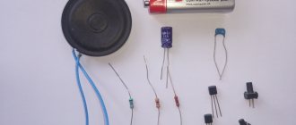
We take the following parts extracted from previous devices:
- The chip itself.
- Stepper motor.
- A pair of steel bars.
When creating the controller case, you also need to take an old cardboard box. It is acceptable to use boxes made of plywood or PCB, the source material does not matter. But the easiest way to process cardboard is using regular scissors.
Types of Li-ion batteries
Depending on the cathode material used, lithium cells are:
- Lithium-manganese (LiMn2O4, LNO). They have lower internal resistance, high power and moderate capacity - 100–150 Wh/kg. Standard charge and discharge currents are up to 1C, but there are models with a C-rating for charging up to 3C and a C-rating for discharge up to 10C, and in pulse mode - up to 50C. Resource – about 500 cycles. Such drives are used in power tools, power units, and medical equipment.
- Lithium-cobalt (LiCoO2, LCO). They have high energy intensity (150–200 Wh/kg), but are inferior to analogues in thermal stability and service life (500–1000 cycles). Charge and discharge currents for such elements should not exceed 1C. Cobalt-based energy storage devices are becoming less common, but are still used in mobile phones, digital cameras, and laptops.
- Lithium-nickel-manganese-cobalt oxide (NMC, NCM). Provide high power and capacity - 150–220 Wh/kg, withstand 1000–2000 cycles. Standard charge and discharge currents are 1C. Used in medical and industrial equipment, electric bicycles and other types of electric transport.
- Lithium Nickel Cobalt Aluminum Oxide (NCA). They are characterized by high specific energy intensity - 200–260 Wh/kg. They have a service life of about 500 cycles, charging currents of 0.7C and discharge currents of 1C. Provide autonomous power supply for industrial and medical equipment, electric power units and other devices requiring high capacity.
- Lithium iron phosphate (LFP, LiFePO4). They are distinguished by a long service life (more than 2000 cycles), thermal and chemical stability, high operational safety and low internal resistance. Their specific energy intensity is 90–120 Wh/kg, charging current is 1C, discharge current is up to 25C. Such batteries are used in devices for which battery endurance, the ability to operate in cold weather and withstand high load currents are important.
- Lithium titanate (LiTi). They are characterized by a low nominal voltage (2.4 V) and a specific energy intensity of 70–80 Wh/kg, but they charge quickly, have a wide temperature range and a service life of 3000–7000 cycles. Rated charging currents are 1C, maximum – 5C. Permissible discharge currents are 10C, and for pulse charging - 30C. Lithium titanate cells are considered the safest. They are used in street lighting, UPS, and electric vehicles.
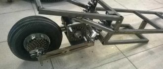
DIY motor and controller for an electric scooter
In this article I will tell you how to make a powerful motor for a scooter or a children's electric car with high efficiency and a simple controller for it at home.
UPD 06/28/2020 ——————————>
This is what ended up happening: the engine described in the article below without changes, added an adjustable power source and throttle trigger, a small battery in the handlebar bag 8S1P 2.5 Ah (quickly replaceable, you can take several with you, one such battery is enough for 9-12km at medium speed)
Battery consumption depends on the speed, I attach a table of energy consumption for my weight of 85 kg:
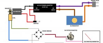
The controller is now a full bridge with 4 IRFB4110 transistors installed without heatsinks, an regulated power supply supplies this bridge with a voltage from 25 to 70V with 24-33V at the input with an efficiency of more than 93%. The overall efficiency of the system was 80-85% (including losses on the battery, controller wires and motor).
<———————— UPD 06/28/2020
The first thing that will shock you is that there will be no iron in this engine. There is no need to cut stator or rotor plates using laser equipment, assemble them into bags, and adjust the entire structure to micron precision. This usually prevents ordinary people from building their own engines. You will be surprised how simple the design is and will not believe the characteristics obtained from it.
Usually, when you type into a search on YouTube, for example, “do-it-yourself electric motor,” you see a coil and a magnet and it rotates and everyone knows that yes, it works, but the efficiency is negligible and cannot create normal traction. But everyone is wrong; in fact, using the right coil and magnet, you can make a powerful motor with high efficiency.
Where it all began. Once, while looking through patents for motors, I noticed a motor made from a coil inside which a long magnetic rod attached to a shaft rotated; this design did not become widespread due to low efficiency due to weak magnets that were available at that time and a slightly incorrect design. Looking ahead, I’ll tell you what the ideal design of the engine should be - a spherical magnet fixed on an axis with poles perpendicular to the axis, a round coil of square cross-section is located around it (the axis passes through it, so it can be divided into 2 parts and placed closer to the axis) - that’s it - the design is ready, All that remains is to fix everything in the housing and you will get a two-stroke engine. True, I have not yet been able to find such a magnet for sale, but if everyone starts making such motors, they will appear soon.
Now there are magnets on sale: cylinders diametrically magnetized with a hole along the axis, they fit almost perfectly (there are no better ones at the moment), they are generally not cheap, but they are still 2-5 times cheaper than ready-made motors, the largest inside are coils with current (15A 100-200 turns) cannot be turned by hand (by the magnet, not by the axle, but by the axle and with pliers). My first concern was when I started such an engine on a scooter - whether it would accidentally break the toothed belt during startup. That is, you understand that these are no longer those toy motors with a coil and magnet that you see on YouTube.
Now about the efficiency, everything turned out to be very simple and predictable: when the magnet cylinder (sphere) is turned with its poles towards the turns of the coil, then the force of the magnetic field acts on the magnet tangentially, that is, perpendicular to the radius, creating a maximum torque, and when it is turned with its poles along the axis of the coil, then the torque is zero, which means that in this position, if you apply current to the coil, it will heat up 100% and the rotation efficiency = 0%, and when it is turned with its poles towards the coil, the efficiency is maximum and depends on the steady current at a certain load. For example, if at this point, with a supply voltage of 10V, a current of 1A is established, then the total resistance (active + reactive) = 10 Ohms and if the resistance of the winding itself is 1 Ohm, then the efficiency at that point is 90% (and, accordingly, if the winding resistance is 0.1 Ohms then the efficiency is 99%). Conclusion - the winding should have as little resistance as possible and it should be powered at those points where the efficiency is maximum; they definitely cannot be powered when the magnet is rotated along the axis or almost along the axis since this is 90-100% loss (heating). And you can be convinced of this if you assemble a simple driver with 2 keys (diagram at the end of the article) and apply control from the microcircuit from almost any cooler with 4 outputs (a cooler control controller with a built-in hall sensor and 2 outputs that are usually connected directly to the windings). The efficiency will be at 55% (maximum 72.2% minus resistance losses depends on the load on the engine). You probably already understand how to increase efficiency, reduce the feeding angle from 180 degrees to 90 - 45 - 30 - 15, the lower the efficiency is closer to 100% but the thrust decreases. Where is the reasonable limit, it turns out that at 180 angle we consume 100 W and give 50-70 W to the load, if we reduce the angle to 90 then we consume 50 W and give it to the load 37 - 44 - (maximum 89.97% - losses) the efficiency is higher but the output power lower at the same supply voltage, 120 degrees (it will be similar to a 3-phase theoretical maximum of 86% - losses on active resistance). Do you need an engine with high uniform thrust and 95% efficiency? It’s easy - take 6 magnets on one axis with a 30-degree shift in the angle of the coils or magnets, we get a 6-phase 12-stroke engine (analogous to a 12-cylinder internal combustion engine) with an efficiency of up to 97.2%, which can also be reprogrammed to any other phase angle and sacrificing the efficiency to increase the thrust by another 2 -3 times if necessary.
The sketch below shows the design of the motor and the placement of the hall sensors (in the example, the hall sensors are separated from the middle of the coil at an angle of 45 degrees, which gives a 90-degree angle for feeding the windings when the magnet poles are as close as possible to the turns of the coil)
My single-phase two-stroke engine with a power angle of 110 degrees produced an efficiency of 87% at a speed of 13 km/h with a load of 92 kg on a flat road, while the windings sealed in a closed wooden case in an hour of continuous driving heated up to 41 degrees with an average engine consumption of 88 W. Two windings of 125 turns in parallel with a wire with a diameter of 0.83 mm, a magnet 65 in diameter, 30 in height, internal 18 mm link. The total copper is 260 grams per 260 W. My weight is 85 kg (scooter 8 kg with motor and battery, lighter only made of carbon), powered by 10x Samsung INR18650-25R = 87 W/hour (42V maximum with a tap from the middle, 2.5 A/h) a full charge lasts me for ~15 km on a flat road.
Initially, 1 hall sensor was used (but I already knew then that this was a big loss since I had made such engines before), so the engine at idle consumed 42 W (1 A for each half of the battery, a total of 2 * 21 or 1 * 42) and in 2 minutes it heated up to 50 degrees (this is without load), installing 2 hall sensors reduced the no-load current by 10 times! and it was 100 mA (4.2 W) and it stopped heating. At maximum load (driving uphill), the current reached 6 amperes (>250 W) and the winding warmed up so that it was impossible to drive for more than a couple of minutes, and after installing 2 hall sensors and supplying power to the windings only at the right moments, according to the figure above, it completely resolved overheating problem (efficiency increased significantly) and the current when driving up the same hill dropped by 2 times (130 W)
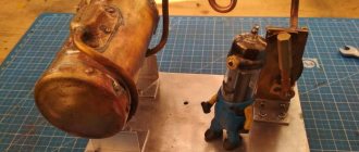
And so the magnets with coils are packed in a housing, the shaft (an M6 100mm bolt on which there are nuts with a flange, wheel clamps, a magnet is fixed through a washer and a rubber gasket) is fixed in non-magnetic steel bearings (this is ideal, but I used ordinary cheap steel ones but the strength the magnetic field is such that they spin with difficulty, so it’s better to install stainless steel right away) and the most important thing is how to start it now. I used the simplest option, one coil and one magnet - the cheapest option and ideal for a scooter, naturally, since we only power a 90 - 120 degree sector per stroke, the sectors remain unfilled with thrust and such an engine will start with a push, but this is not a fan and the engine for the scooter, pushed off, turned on the engine and drove off, everything is simple. If you need an autostart, then at least you need to make a 2-phase 4-stroke, this is what I installed in a children's car.
Controller
I associate the phrase “pWm regulation” with losses, you need to power it with direct current to avoid switching losses on the switches and not heat up the diodes in the switches, in general the controller can operate with an efficiency of 97% or higher if you forget about the PWM, and the speed is better regulated by the supply voltage (for example, in my scooter it is fixed at 13 - 18 km/h depending on the weight of the rider). Powering the winding in two cycles is possible either by a bridge, but then the losses are always on 2 switches or by a half-bridge with power supply tapped from the middle point, this option was chosen because it reduces losses on the switches by 2 times (the coil is always turned on only through 1 switch). Another advantage of such a half-bridge is that when the coil is turned off, the back emf is drained through 1 diode into the opposite arm and the losses on the diodes are also 2 times less, that is, more energy will return to the capacitor / battery, as well as from recovery from rolling down the hill. As a result, we get a half-bridge + half-bridge driver + control circuit.
Control circuit
Using one hall sensor does not make it possible to control the angle at which the winding is energized, so you need at least 2 sensors located in such a way as to get the windings turned on in the desired range, the easiest way is to make an angle of 90 degrees (for this you need to space the sensors 45 degrees from the turns of the coil to both side) then a pair of sensors will be enough for 4 cycles (we use only 2 of them for single-phase). Each sensor returns 2 positions which mean whether it sees the north or south pole, so when both see the north we turn on one key, when both see the south the second, when using microcircuits from the cooler - it is implemented by 2-or-not logic, power is supplied to the inputs of two logic elements Through the resistance at the outputs at this 0, the cooler microcircuits switch the inputs of the logical elements to zero, when both inputs are at zero at output 1, 1 switch is turned on, and also when both inputs on the second logical element are at zero, another switch is turned on. It's simple. When choosing a cooler driver microcircuit (Hall sensor), take into account that they are available with and without stop protection; for a support motor like the one on my scooter, it is better to use one with protection; it will start only when you start riding, but for an engine that must start on its own, you need to choose without protection and do it if necessary in another way (overcurrent protection, for example).
I didn’t have logic chips, so I replaced them with transistors. Connection diagram for the mosfets driver according to the datasheet.
Engine debugging
I would like to note important points that will protect the controller parts from accidental burning. The fact is that the back emf from the coil is a very insidious thing, it can burn all the electronics and the driver and microcircuits with the hall sensor. To prevent such situations, there must be capacitors at the power input into which the back emf from the coil is drained (through protective diodes in mosfets) in case of accidental battery disconnection, at least 1000 uF 50V with low esr. Also, to prevent high voltage surges from reaching the driver output through the reverse capacitance of the mosfet, there must be a 13-15V zener diode in the gate-source circuit (which is lower than the permissible gate voltage of 20V but higher than the control voltage from the driver 12V).
When you turn it on for the first time, it is better to connect the winding through a resistance that limits the maximum current (10-50 Ohms); by turning the hall sensors over, we achieve rotation in the desired direction. Also, by moving the sensors, you can find positions where consumption at idle will be minimal and engine operation will be quiet. It is not worth greatly reducing the power angle (< 90 degrees) for a two-stroke engine, although consumption will be lower at idle, it will be more difficult to create sufficient thrust since more power will have to be invested in shorter periods of time, which means additional losses on the controller and battery.
Price
- bolt (shaft), nuts and washers (fixing the magnet and bearings), non-magnetic screws (stainless steel, for twisting the housing) < $2
- body (beam 1.5m x 80 x 20) = $1.3
- gears and belt = $8
- magnet = 50$
- boards and all parts < $10
- 10x Samsung INR18650-25R = $38
In total, electrifying the scooter cost ~$110
Advantages and disadvantages
Pros:
- the engine rotates without any resistance, which does not interfere with riding the scooter as usual when the power is turned off
- light weight
- price
- high efficiency
Minuses:
- You cannot install such a motor near magnetic materials (it will lead to sticking of the rotor; the use of iron bolts in the housing is also unacceptable, only stainless steel or glue)
- cannot be installed very close to massive conductive materials (braking by eddy currents, it is ideal to use a frame made of plastic, wood, carbon, then you can place it anywhere)
- come up with an idea and write in the comments (low speed doesn’t work, you can raise the voltage, I’m happy with the speed for driving on pedestrian paths)
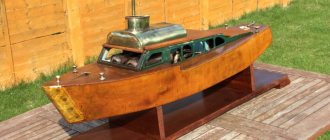
Big photo
Pressing the belt for more grip on the gear
First starts (with 1 more hall sensor and reduced supply voltage 2x8V) maximum speed 3-5 km/h
Setting the position of the sensors (we drive around, measure consumption, re-glue the hall sensor and look for the optimal option) in the photo is optimal
How does a lithium battery work?
The principle of operation of Li-ion batteries is identical for elements of all types, regardless of the cathode material. When voltage is applied to the electrodes - “plus” to lithium oxide and “minus” to graphite - positively charged lithium ions are detached from the oxide molecules and transferred to the carbon plate. As a result, an oxidation reaction occurs and the battery is charged.
When a lithium battery operates under load, the reverse process occurs. The Li+ ions return to the lithium oxide plate to their standard state. A graphite plate on a copper foil becomes a “minus”, and a lithium oxide on an aluminum foil becomes a “plus”.
Conclusions and useful video on the topic
The desire to make equipment for home use with your own hands is sometimes stronger than the simpler solution - buying an inexpensive device. See what came out of this in the video:
Assessing the prospects for manufacturing electronics on our own, regardless of its purpose, we have to face the idea that the age of “homemade” is coming to an end.
The market is oversaturated with ready-made electronic devices and modular components for almost every household product. Amateur electronics engineers now have only one thing left to do - to assemble home construction kits.
Do you have anything to add, or do you have any questions about assembling and using controllers for a wind generator? You can leave comments, ask questions and add photos of your homemade products - the contact form is in the lower block.
Features of charging Li-ion cells
Lithium-ion batteries are sensitive to overcharging. When overcharged, lithium metal is deposited on the anode surface. It appears as a fine mossy residue and is capable of reacting with the electrolyte. Oxygen is actively released at the cathode during recharging. Externally, this can manifest itself in the form of intense heating, increased pressure and depressurization of the element.
Li-ion batteries are charged in 2 stages:
- With a stable current value of 0.2C–1C up to the voltage recommended by the manufacturer, usually 4.1–4.2 V. This stage lasts about 40 minutes.
- At constant voltage. The charging process is completed when the charging current decreases to 3% of the initial value.
Charging occurs faster in pulse mode. But to extend the service life of lithium cells, it is recommended to charge them with a current whose nominal value is 50% of the capacity value, i.e. 0.5C.
We use Turbo CNC - a control program
Turbo CNC software will definitely work with a microcontroller that uses the ULN2003 chip.
- We use a specialized website from where you can download software.
- Any user will understand how to install.
- This program works best under MS-DOS. Some errors may appear in compatibility mode on Windows.
- But, on the other hand, this will allow you to build a computer with certain characteristics that are compatible with this particular software.
Lithium battery protection
Lithium-based batteries are protected from short circuits within the system, for example, using a 2-layer separator. One of its layers is made not from polypropylene, but from an analogue of polyethylene. If there is a risk of a short circuit, for example, if lithium dendrites grow towards the cathode, the protective layer locally heats up, partially melts, becomes impenetrable and blocks subsequent dendritic growth.
To protect against overcharge and deep discharge, energy storage devices are equipped with special limiters - current and voltage protection boards. They do not allow the voltage to go beyond the recommended range and, in critical situations, automatically disconnect the element from the power supply or load.
Therefore, for the safe operation of cells and batteries, it is important to use BMS boards. Otherwise, there is a high risk of damage to the batteries and their premature failure. Such a charge-discharge process controller can be installed on both individual batteries and a battery assembled from them.
Will the game be worth the candle?
If we consider everything from the point of view of the logic of an ordinary person who is not passionate about radio engineering, then, naturally, it will not be more expensive to purchase a cheap controller. In addition, no time will be lost creating with your own hands. But for a true radio amateur, and sometimes just a passionate person, assembling such a device yourself is much more pleasant than buying it somewhere in a store. But it’s still worth trying to make a controller yourself, because nothing can replace the pleasure of the work done (and a successful one at that).
About PWM regulator
PWM (PWM) controller for wide application - a device designed for smooth switching on, off and adjustment of power, speed, brightness and more.
Previously, to regulate the speed of electric motors, the supply voltage was changed. However, in modern electrical engineering this has been abandoned. Now the adjustment occurs by applying current pulses to the electric motor, which have different durations. This is what PWM (pulse width modulated) regulators do, which have recently become more and more popular.
PWM controller circuits are universal - they are suitable for adjusting the brightness of lamps, and for adjusting the speed of motor revolutions, and even for regulating the current strength in the charger.
The scope of application of PWM regulators is very wide.
Review of the board
Assembled homemade PWM regulator board:
Source prom.st
The board is controlled manually and is carried out by a variable resistor or external voltage in the ranges:
0.45 V – device is turned off, duty cycle is 0%
0.5/3.5 V – smooth regulation, duty cycle from 0.1% to 99.9%
3.6 V – device on, duty cycle – 100%
The device operates at a constant voltage of 10 to 28 Volts.
The maximum voltage is limited by the maximum permissible voltage of the power switches, as well as the reverse voltage of the high-power diode in the load, when separate from the additional 15 V control power supply.
I advise you not to install a stabilizer if the voltage does not reach 15 Volts.
Instead, some kind of diode or regular jumper would be better.
If the voltage is from 15 to 28 Volts, then it is worth installing a linear (for example, 7815) or pulse stabilizer in the form of a ready-made module on the MP2307, and you must set the voltage on it to 15 Volts.
You can order them on the same Aliexpress.
If necessary, you can adjust the frequency with a continuously variable resistor.
To do this, you need to connect it to the board instead of a jumper.
Literature
1. Chigarev M. Battery charge control chips from ON Semiconductor // Electronics News, No. 3, 2010.
2. Nikitin A. Integrated battery charge control circuits produced by Maxim // Electronics News, No. 15, 2009.
3. Khrustalev D.A. Batteries. - M.: Izumrud, 2003.
4. L6924U. USB compatible battery charger system with integrated power switch for Li-Ion/Li-Polymer // Material from STMicroelectronics. Posting on the Internet: Link
5. Camiolo Jean, Scuderi Giuseppe. Reducing the Total No-Load Power Consumption of Battery Chargers and Adapter Applications Polymer // Material from STMicroelectronics. Posting on the Internet: Link
6. Maximum power point tracker. Wikipedia article. Internet page: https://en.wikipedia.org/wiki/Maximum_power_point_tracker
7. STEVAL-ISV012V1: lithium-ion solar battery charger//Material from STMicroelectronics. Posting on the Internet: Link.
Obtaining technical information, ordering samples, delivery - e-mail
•••
General assembly principle for any 18650 charger
First of all, you need to make a board. You can develop it yourself (in programs like Sprint LayOut), or you can find a ready-made one on the Internet. Then there are two ways:
- Make a board using the LUT method or other home technology.
- Order a board in China.
In the second option, the board will obviously be of better quality, but it will cost more, and you will have to wait more than one day.
When assembling a charger for 18650 batteries on specialized microcircuits, you must keep in mind that their cases are often subminiature, and soldering such elements requires special skills.
Marking
All parameters of a lithium-ion battery can be found out from the markings on the case. The labeling option may differ for each type of battery. There is no uniform labeling standard yet. But it’s quite easy to understand it, knowing the typical parameters and notations:
- Letters. The first letter is always I, as it denotes the type of technology, i.e. lithium ion. The second letter specifies the composition; there are markings such as M, F, C, N. The third letter indicates that the battery is rechargeable, marking R.
- Numbers. Digital markings indicate dimensions in millimeters. Thus, the first 2 digits are the diameter, the next two are the length. A zero at the end of the marking may indicate a cylindrical shape.
To clarify the values, you must refer to the battery documents or the manufacturer. Each of them may have different markings. There is also no standard for applying a production date marker.
What you need for a homemade memory
First of all, you will need to select a charging scheme for 18650 cells. It is selected according to the necessary parameters, as well as the availability of parts. Secondly, the skills of reading circuit diagrams, making printed circuit boards at home (or at least ordering them from China, which is not so expensive now), soldering microcircuits and other elements, finding errors and malfunctions. If you don’t have this, you shouldn’t even read what you will need:
- radioelements according to the diagram;
- soldering iron with a set of consumables;
- board or blank for it and accessories for self-production.
You will also need a case for installing batteries for charging (it makes it more convenient to connect the battery to the charger).
Plastic case for connecting 18650 battery.
It is better to develop skills separately, and then take on the production of these devices. They are not very difficult, but require a conscious approach.