Since I spend quite a lot of time in the workshop, I try to arrange it for maximum efficiency. The same goes for various tool improvements. In particular, one day I needed to make a speed controller for the electric motor of a sharpener, since I have to work with different materials, and some of them are sensitive to friction. Plus, the electric motor has a smooth start with simple controls. Assembling the speed controller of a commutator engine with your own hands without loss of power is not very difficult. Next, I will show the progress of the work and show how to improve the existing scheme. After all, as you know, the first principle of electrical engineering is: the simpler, the better.
Source forumcnc.ru
Using frequency converters
To adjust the speed of an electric motor operating from a network with a voltage of 220 and 380 Volts, frequency converters can be used. High-tech electronic devices allow, by changing the frequency and amplitude of the signal, to smoothly regulate the speed of the electric motor.
Such converters are based on powerful semiconductor transistors with wide-pulse modulators.
Converters, using a corresponding control unit on a microcontroller, allow you to smoothly change the engine speed.
High-tech frequency converters are used in complex and loaded mechanisms. Modern frequency regulators have several degrees of protection , including load, voltage current and other characteristics. Some models are powered from a single-phase power supply of 220 Volts and can convert the voltage to three-phase 380 Volts. The use of such converters allows you to use asynchronous electric motors at home without the use of complex wiring diagrams.
Step-by-step instruction
The classic sinistor circuit works on the principle of charging a capacitor through a low-capacitance resistor. After the voltage between the plates reaches the desired value, the triac begins to pass current to the load.
In this way, you can control the capacitance of the capacitor by changing the voltage that goes to the load. A rheostat, which is installed in place of the resistor, is perfect for this.
Unfortunately, such a circuit heats up quickly, which is why it is necessary to install an additional radiator to effectively remove heat.
This installation can operate from an internal storage device with a voltage of 12 V and an external one of 220 V. However, in this case, a quenching circuit is required.
In this operating mode, you can change the threshold power, this directly affects the power of the rotor. Power resistors are set to specific readings of the incoming current, collecting it in the required volumes.
Application of electronic regulators
The use of powerful asynchronous motors is impossible without the use of appropriate speed controllers. Such converters are used for the following purposes:
- Stepped acceleration and the ability to reduce engine speed when the load decreases allows you to reduce energy consumption. The use of frequency converters with powerful asynchronous motors allows you to halve your energy costs.
- Protection of electronic mechanisms. Frequency converters allow you to monitor pressure, temperature and a number of other parameters. When using an engine as a pump drive, a pressure sensor can be installed in a container into which liquid or air is pumped, which is responsible for controlling the mechanism and preventing its failure.
- Ensuring a smooth start. When starting the electric motor, when the motor immediately begins to operate at maximum speed, the drive experiences an increased load. The use of a speed controller ensures smooth starting, which guarantees the maximum possible durability of the drive and the absence of serious damage.
- Maintenance costs for pumps and the power units themselves are reduced. The presence of speed regulators reduces the risk of breakdowns of individual mechanisms and the entire drive.
The operating scheme used by frequency converters is similar to that of most household appliances. Similar devices are also used in welding machines, UPSs, power supply for PCs and laptops, voltage stabilizers, lamp ignition units, as well as in monitors and LCD TVs.
Despite the apparent complexity of the circuit, making a speed controller for a 220 V electric motor will be quite simple.
Let's connect first
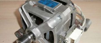
Before adjusting the speed of the washing machine engine, it must be connected correctly. The commutator motors from automatic washing machines have several outputs, and many novice DIYers confuse them and cannot understand how to connect. Let's talk about everything in order, and at the same time check the operation of the electric motor, because there is a possibility that it is completely faulty.
- First you need to take the motor from the washing machine, spin it and find the excitation coils or shoes, from which 2, 3 or more wires should come. The shoes look something like the picture below.
- We take an ohmmeter, set the toggle switch to the minimum resistance and begin ringing all the outputs one by one. Our task is to select from all the outputs of the excitation coil 2, which have the highest resistance value; if there are only two of them, then there is no need to select anything.
- Next you need to find the motor commutator and brushes, from which 2 wires will also come. In this case, there will be only two outputs; if there are more, it means you have mixed up something or one of the wires is simply torn off.
- The next group of outputs that we desperately need to detect are the tachometer outputs. In some cases, the wires coming from the tachometer can be seen directly on the engine housing, but sometimes they are hidden in the depths of the housing and then, in order to connect, you have to partially disassemble the engine.
- Next, we take one wire coming from the collector and connect it to one of the coil wires.
- We connect the second wire of the collector and the second wire of the coil to a 220 V network.
- If we need to change the direction of rotation of the armature, then we simply swap the places of the connected wires, namely, the first wire of the collector and the first wire of the coil are connected to the network, and the second wires are connected to each other.
- We mark the wires of the coil, tachometer and collector with labels so as not to confuse them and perform a test run of the engine.
Connect via voltage regulator
The simplest option for adjusting the electric motor of a washing machine is to use any voltage regulator (dimmer, drill trigger, etc.). The meaning of the adjustment is that the maximum voltage is first applied to the engine, and it rotates at maximum speed. By turning the dimmer switch, we reduce the voltage, and the engine accordingly begins to reduce speed. The connection diagram is as follows:
- We connect one coil wire to one armature wire;
- connect the second wire of the coil to the network;
- we connect the second armature wire to the dimmer, and connect the second output of the dimmer to the network;
- We test run the engine.
We check how the engine operates at minimum power. You can see that even at minimum power the idle speed is impressive, but you just need to lean a wooden block against the rotating axle and the engine immediately stops. What is the conclusion? And the conclusion is that this method of adjusting the speed of the washing machine electric motor leads to a catastrophic loss of power when the voltage decreases, which is unacceptable if you are going to make some kind of homemade product out of the engine.
Initially, we set the task of learning to regulate the speed of the washing machine engine with our own hands without loss or with minimal loss of power, but is this possible? It is quite possible that the connection diagram will simply become somewhat more complicated.
How the device works
The operating principle and design of the engine speed controller is simple, therefore, having studied the technical aspects, it is quite possible to perform them yourself. Structurally, there are several main components that make up the rotation controllers:
- Electrical engine.
- Converter block and microcontroller control circuit.
- Mechanisms and drives.
The difference between asynchronous motors and standard drives is the rotation of the rotor with maximum power when voltage is applied to the transformer winding. At the initial stage, the current consumption and power of the motor increases to a maximum, which leads to a significant load on the drive and its rapid failure.
When the engine starts at maximum speed, a large amount of heat is released, which leads to overheating of the drive, windings and other drive elements. Thanks to the use of a frequency converter, it is possible to smoothly accelerate the engine, which prevents overheating and other problems with the unit. When using a frequency converter, the electric motor can be started at a speed of 1000 revolutions per minute, and subsequently smooth acceleration is ensured when 100-200 engine revolutions are added every 10 seconds.
Which engine to choose to make a circular machine
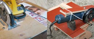
Every owner would like to have a device for working with lumber in a garage, in a country house, in a private house or when renovating a city apartment. But even a hand-held circular saw costs from 10,000 rubles. In this article we will talk about how a circular machine is made from an engine from a washing machine that has served its life. This homemade electric saw, assembled with your own hands at home, is capable of unraveling boards five centimeters thick. At the same time, it weighs just over 20 kilograms and is easily transported in the trunk of a car.
A circular saw is always useful on the farm: at the dacha or in a private house. But not everyone can afford a good expensive tool, and a cheap analogue quickly breaks down. The way out of the situation is to make a circular saw with your own hands. For example, you can make it from an engine from an old automatic washing machine, which is a shame to throw away and takes up space.
The working motor from an automatic washing machine should not gather dust in the garage. Even a home craftsman can find a use for it. We will tell you how to make a homemade circular from a washing machine engine.
This tool will help you cut wood and master carpentry.
However, be careful: careless use of a homemade machine can lead to unpleasant consequences. Therefore, before you take on a job, you must be completely confident in your abilities.
A 350 mm disk will require 1 kW of energy to start. A disk with a diameter of 170 mm will require about 500 W. Therefore, you can install a motor from an old washing machine.
In the washing machine, the speed is controlled by a tachometer, which is controlled by a control module. But it is impossible to connect a module to the circular, so install a voltage regulator. Use the wiring diagram to correctly install the motor.
You have figured out which motor is needed and how to connect it. Now consider the design diagram of a circular saw.
The main load will be on the moving elements. This:
- saw and electric motor shaft;
- motor pulley and saw shaft;
- drive belt.
Let's look at the features of each of them:
- The drive belt does not have to be taken from the washing machine; other belts can be used. The main thing is that they have serrations, like a V-belt.
- Flow grooves need to be made on the small pulley. The belt will cling to them during operation, which will prevent slipping.
- A larger disc is welded onto the large pulley, which will prevent the belt from slipping off.
- To fasten the circular saw, use a shaft into which it is mounted, as well as a washer and nut, which are used to secure it. It is recommended to select or take this kit from the factory to ensure the drive is secured as securely as possible.
When creating a design, you need to take into account that it is designed for a three-hundredth disk. Of course, a self-made circular machine is only suitable for household use. Therefore, try not to overload the engine.
Often such machines are stored in the yard, on the street, so protect the electrical part from moisture.
The frame is made of metal sheet 3 mm thick. Before making the frame, prepare a 30 mm metal corner.
As shown in the photo above, the craftsman installed the frame into homemade pipe racks. Now it is possible to adjust the height of the device. However, it is recommended to make a solid frame by welding pieces of corner together. Strong vibration over time loosens the fastenings of bolts and other elements.
We suggest you read: Zanussi washing machine does not turn on reasons
Please note that the mini circular saw varies in size. It is much smaller than usual and can fit into a pantry when stored.
A washing machine is a useful thing in the household. However, over time the device breaks down. There is an element in the washing machine that should not just be lying around in the garage - this is the motor. It makes an excellent circular saw.
Making homemade relays
Making a homemade speed controller for a 12 V electric motor will not be difficult. For this work you will need the following:
- Wirewound resistors.
- Switch for several positions.
- Control unit and relay.
The use of wirewound resistors allows you to change the supply voltage and, accordingly, the engine speed. Such a regulator provides stepwise acceleration of the engine, has a simple design and can be made even by novice radio amateurs. Such simple homemade step regulators can be used with asynchronous and contact motors.
Operating principle of a homemade converter:
- Power from the network is sent to the capacitor.
- The used capacitor is fully charged.
- The load is transferred to the resistor and the bottom cable.
- The thyristor electrode connected to the positive terminal on the capacitor receives the load.
- A voltage charge is transmitted.
- The discovery of the second semiconductor occurs.
- The thyristor passes the load received from the capacitor.
- The capacitor is completely discharged, after which the half-cycle is repeated.
In the past, the most popular were mechanical regulators based on a variator or gear drive. However, they were not very reliable and often failed.
Homemade electronic regulators have proven themselves to be the best. They use the principle of changing step or smooth voltage, are durable, reliable, have compact dimensions and provide the ability to fine-tune the operation of the drive.
The additional use of triacs and similar devices in electronic regulator circuits allows for a smooth change in voltage power; accordingly, the electric motor will correctly gain speed, gradually reaching its maximum power.
To ensure high-quality regulation, variable resistors are included in the circuit, which change the amplitude of the incoming signal, providing a smooth or step change in the speed.
Measurements
It is clear that the number of revolutions needs to be determined somehow. Tachometers are used for this. They show the rotation number at the moment. You can’t simply measure speed with a regular multimeter, except in a car.
As you can see, on electric machines you can change various parameters, adjusting them to the needs of production and household use.
DIY birthday decor
Close…
Pointed-toe cowboy bootsThe principle of operation of a homemade lock is as follows. In one half there is a permanent magnet. and in the other there is a metal plate. One of them is attached to the door. The second, with the metal plate removed, is equipped with a KEM-1 reed switch and attached to the door frame. If the door is in the closed position, the two parts of the lock are pressed, the magnet acts on the reed switch, closing its contacts. If the door opens, the magnet goes away and the reed switch contacts open.
The battery, the computer system unit, even the power supply for a laptop are all best friends. I’m already silent about such good hot water bottles as my husband and I.
Take the filler and stuff the doll. When the stuffing is completely evenly distributed, sew the product up. The handles must be sewn to the body almost near the neck.
From one pallet, sanded, impregnated and varnished, you get a garden table like a coffee table, on the left in Fig. If you have a pair in stock, you can make a wall-mounted work desk-rack out of them in literally half an hour, in the center and on the right. You can also weave chains for it yourself from soft wire, covered with a PVC tube or, better, heat-shrinkable. To fully raise the tabletop, small tools are placed on the shelf of a wall pallet.
Well, if you fill a glass bowl, vase, candy dish, punch vessel or ordinary glasses with water, scattering sea pebbles on the bottom, and let the candle-tablets float freely, you will get magical lighting for a romantic New Year. For a more interesting and unexpected effect, you can experiment with the color of the water. How are studs installed on rubber?
Handmade toys for children are beautiful, cheap and enjoyable. Every child needs original and educational toys, but it is not always possible to purchase them. Today we will show you 5 examples of fun toys that you can make yourself. They can be made from cardboard, paper or wood. In general, be inspired and make your children happy more often.
For the base of such a structure, you can use thick plywood, and for its upper part - polycarbonate. Finding solar panels online today is also not a problem.
Attention! When joining panels, do not use too much force, as you may damage the joint. This is exactly how many knives a housewife should have in her kitchen so that the cooking process is always simple and enjoyable.
This is exactly how many knives a housewife should have in her kitchen so that the cooking process is always simple and enjoyable.
To make a feeder with your own hands we will need:
Timber calculation. The boards, called staves, have biconvex sides to give the cooperage product a convexity. To make them like this, you need to take the lower part of a tree trunk and split it, similar to chopping wood. If you cut it carefully, the natural integrity of the fibers will be disrupted, which is bad for such a product. You shouldn’t start figure sawing right away - the logs need to be dried for 2 months. Moreover, dry it not under the scorching sun, but in a dark, cool room.
How to weave bracelets from laces
The fact that most New Year's costumes for preschool children are easily sewn on the basis of overalls can significantly narrow and facilitate creative search. If you learn how to sew a jumpsuit - the basis for a New Year's costume and come up with (draw from) and make decorative elements for it with your own hands, then you can make amazing and quite interesting models of New Year's outfits for children. The main thing is to think through everything in advance to the smallest detail, arm yourself with knowledge on the topic - so that the result of the work will pleasantly surprise and delight everyone.
Wardrobe design
Images
DIY birthday gift for mom photo instructions
Similar news
.
With the ever-increasing growth of automation in the domestic sector, there is a need for modern systems and devices for controlling electric motors.
Control and frequency conversion in small-power single-phase asynchronous motors, launched using capacitors, allows you to save energy and activates the energy saving mode at a new, progressive level.
PWM transistor circuit
You can regulate the shaft rotation speed of low-power electric motors using a transistor bus and a series connection of resistors in the power supply. This option is easy to implement, but has low efficiency and does not allow smooth changes in engine rotation speed. Making your own speed controller for a 220 V brushed motor using a PWM transistor will not be particularly difficult.
The principle of operation of the transistor regulator:
- Bus transistors used today have a sawtooth voltage generator with a frequency of 150 Hertz.
- Operational amplifiers are used as a comparator.
- The rotation speed is changed due to the presence of a variable resistor that controls the duration of the pulses.
Transistors have an even constant pulse amplitude, identical to the amplitude of the supply voltage. This allows you to adjust the speed of the 220 V engine and maintain the operation of the unit even when applying a minimum voltage to the transformer winding.
Thanks to the ability to connect a microcontroller to a PWM transistor, it is possible to automatically configure and adjust the operation of the electric drive. Such converter designs may have additional components that expand the functionality of the drive, ensuring operation in a fully automatic mode.
Thyristor control of electric motor speed
The thyristor regulator also allows you to change the speed of the power unit shaft. It is also called a dimmer or phase regulator. With this connection method, the electric motor is connected either to a break in the network cable, or behind a rectifier bridge that powers the anode thyristor circuit. This method of controlling the motor speed is considered quite reliable, provided that there are no violations of the integrity or order of contact connections in the load circuit. If you connect a commutator electric motor through a thyristor regulator, the brushes may begin to spark, since the load current will pulse.
Although, to control 12-volt DC motors of the collector type, you can adapt a thyristor regulator, which will have some features:
- the electric motor and power thyristor are connected to one of the diagonals of the rectifier bridge, and the voltage from the mains is supplied to the other diagonal;
- Thyristors are controlled not with short pulse signals, but with a wider range, which makes it possible to eliminate the detrimental effect on the operation of the regulator of short-term load drops characteristic of commutator electric motors.
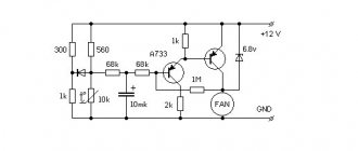
The generator of short, up to several milliseconds, positive pulses is assembled on a unijunction transistor VT1. It is designed to operate the auxiliary thyristor VS1. The trapezoidal supply voltage is supplied to the generator by limiting the 100-Hz positive half-waves of the sinusoidal voltage by the zener diode VD1. Each such half-wave gradually charges capacitor C1 through the resistive chain R1-R3.
When the voltage required to open the transistor appears on the capacitor, a positive pulse is applied from resistor R5 to the electrode of the control trinistor VS1, as a result of which this trinistor opens, and the power trinistor VS2 receives a pulse signal that is longer than the control signal and Electric motor M1 receives power.
The rotation speed of the electric motor rotor is adjusted using a variable resistor R1, which is responsible for the opening moment of the power and control thyristors, and therefore for the load power. The anode of the VS2 thyristor in its circuit has an inductive load, so spontaneous opening is possible even without receiving a control signal. To prevent this from happening, a diode VD is mounted, connected in parallel with the excitation winding LB.
Introduction of automatic control systems
The presence of microcontroller control in regulators and frequency converters makes it possible to improve the operating parameters of the drive, and the motor itself can operate in a fully automatic mode, when the controller used smoothly or stepwise changes the rotation speed of the unit. Today, microcontroller control uses processors that have a different number of outputs and inputs. You can connect various electronic keys, buttons, various signal loss sensors, and so on to such a microcontroller.
On sale you can find various types of microcontrollers , which are easy to use, guarantee high-quality settings for the operation of the converter and regulator, and the presence of additional inputs and outputs allows you to connect various additional sensors to the processor, based on the signal of which the device will reduce or increase the number of revolutions or completely stop supplying voltage to the motor windings.
Today, various electric motor converters and controllers are available on the market. However, if you have even minimal skills in working with radio components and the ability to read diagrams, you can make such a simple device that will smoothly or stepwise change engine speed. Additionally, you can include a control triac rheostat and a resistor in the circuit, which will allow you to smoothly change the speed, and the presence of microcontroller control completely automates the use of electric motors.
How to make a device for changing the rotation speed of an electric motor with your own hands
Dimmers can be used to regulate low-power single-phase IM. However, this method is unreliable and has serious disadvantages: reduced efficiency, serious overheating of the device and the risk of engine damage.
For reliable and high-quality regulation of the speed of 220V electric motors, frequency regulation is best suited.
The diagram below allows you to assemble a frequency device for adjusting electric motors with a power of up to 500 W. The rotation speed is changed within the range from 1000 to 4000 rpm.
The device consists of a master oscillator with variable frequency, consisting of a multivibrator assembled on a K561LA7 microcircuit, a counter on a K561IE8 microcircuit, and a half-bridge regulator. Output transformer T1 decouples the upper and lower transistors of the half-bridge.
The damping circuit C4, R7 dampens voltage surges that are dangerous for power transistors VT3, VT4. The rectifier, a supply voltage doubler, includes a VD9 diode bridge, with a filter capacitor on which the half-bridge supply voltage is doubled.
Primary winding voltage: 2x12V, secondary winding 12V. The primary winding of the key control transformer consists of 120 turns of copper wire with a cross-section of 0.7 mm, with a tap from the middle. Secondary - two windings, each with 60 turns of a drive with a cross section of 0.7 mm.
The secondary windings must be insulated from each other as reliably as possible, since the potential difference between them reaches 640 V. The output windings are connected to the switch gates in antiphase.
Design
The design of the RSV variable speed governor is fundamentally different from that of the RQV governor. There is only one adjuster spring (12). When the engine speed is set by the control lever, the spring position and tension are adjusted to the required speed, providing a state of mutual balance between the torque on the idler arm and the torque generated by the weights. All settings on the control lever (7), as well as the stroke of the weight (15), are converted to the control rack through the connecting levers of the regulator.
The trigger spring (2), attached to the upper end of the variable pivot arm (17), pulls the control rack (3) to the starting position, automatically setting the amount of fuel delivered at startup.
The full load stop (18) and torque control mechanism (14 - torque control spring) are built into the regulator. An additional idle speed spring (13) and an adjustment screw built into the governor cover (8) serve to stabilize the idle speed.
One end of the adjuster spring is attached to the tension arm (10), and the other end is attached to the rocker (rocker arm) (5). The rocker screw can be adjusted to change the force that the adjuster spring exerts on the tension arm pivot point. This makes it possible to adjust the governor speed reduction coefficient within certain limits without replacing the governor spring. This is one of the advantages of the RSV regulator. Lighter weights are designed for higher rotation speeds.
Changing the speed of an IM with a squirrel-cage rotor
There are several ways:
- Rotation control by changing the electromagnetic field of the stator: frequency regulation and changing the number of pole pairs.
- Changing the slip of the electric motor by decreasing or increasing the voltage (can be used for IMs with a wound rotor).
Frequency regulation
In this case, the adjustment is made using a frequency conversion device connected to the engine. For this purpose, powerful thyristor converters are used. The process of frequency regulation can be considered using the example of the EMF formula of a transformer:
U1=4.44w1k1fΦ
This expression means that in order to maintain a constant magnetic flux, which means maintaining the overload capacity of the electric motor, the supply voltage level should be adjusted simultaneously with frequency conversion. If the expression calculated by the formula is saved:
U1/f1=U'1/f'1
then this means that the critical moment has not been changed. And the mechanical characteristics correspond to the figure below; if you do not understand what these characteristics mean, then in this case the adjustment occurs without loss of power and torque.
The advantages of this method are:
- smooth regulation;
- changing the rotor speed up and down;
- rigid mechanical characteristics;
- efficiency.
There is only one drawback - the need for a frequency converter, i.e. increase in the cost of the mechanism. By the way, on the modern market there are models with single-phase and three-phase input, the cost of which with a power of 2-3 kW is in the range of 100-150 dollars, which is not too expensive for full adjustment of the drive of machine tools in a private workshop.