There are several reasons to think about how to make cooler speed controllers with your own hands. Most often, this is the noise of this very fan, and in this way you can, if not get rid of it completely, then make it much quieter, that’s for sure. Next I’ll tell you what and how I did to achieve my goal.
Source diodnik.com
speed controller
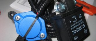
into the open circuit +12V, as shown in the figure. Attention! If your fan has 4 terminals, and their colors are: black, yellow, green and blue (for these, the plus power is supplied via the yellow wire), then the regulator is connected to the gap in the yellow wire.
A ready-made, assembled fan speed controller is installed in any convenient place on the system unit, for example, in the front of a plug in a five-inch bay, or in the back of a plug for expansion cards. To do this, drill a hole of the required diameter for the variable resistor you are using, then it is inserted into it and tightened with the special nut that comes with it. You can put a suitable handle on the axis of the variable resistor, for example from old Soviet equipment.
It is worth noting that if the transistor in your regulator gets very hot (for example, if the power consumption of a cooler fan is high or if several fans are connected through it at once), then it should be installed on a small radiator. The radiator can be a piece of aluminum or copper plate 2 - 3 mm thick, 3 cm long and 2 cm wide. But as practice has shown, if a regular computer fan with a current consumption of 0.1 - 0.2 A is connected to the regulator, then there is no need for a radiator, since The transistor heats up very little.
- Simple scheme
- With temperature sensor
- To reduce noise
- Video
Adjusting the fuel system of a walk-behind tractor
If fuel is not supplied to the cylinder, then, first of all, you need to check whether there is enough fuel in the tank. You also need to check whether it is supplied to the carburetor. To do this, remove the hose from the inlet fitting of the device. If we are talking about a K45 type carburetor, you should press on its quencher so that fuel begins to pour out through the drainage hole.
If fuel does not enter the carburetor, then you need to turn off the fuel supply valve, completely disassemble it and remove accumulations of dirt from the mechanical cleaning filter. To achieve maximum purity, all components must be treated with gasoline. The fuel valve is reassembled and returned to its original location.
If fuel enters the carburetor, but is not supplied to the cylinders, it is necessary to check the correct operation of the fuel valve, as well as the presence of dirt on the jets.
Fan speed controller - simple diagram
The circuit proposed below provides simple adjustment of fan speed without speed control. The device uses domestic transistors KT361 and KT814. Structurally, the board is placed directly in the power supply, on one of the radiators. It has additional seats for connecting a second sensor (external) and the ability to add a zener diode, which limits the minimum voltage supplied to the fan.
List of required radioelements:
- 2 bipolar transistors - KT361A and KT814A.
- Zener diode - 1N4736A (6.8V).
- Diode.
- Electrolytic capacitor - 10 µF.
- 8 resistors - 1x300 Ohm, 1x1 kOhm, 1x560 Ohm, 2x68 kOhm, 1x2 kOhm, 1x1 kOhm, 1x1 MOhm.
- Thermistor - 10 kOhm
- Fan.
Fan speed controller board:
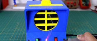
Photo of the finished fan speed controller:
Consequences of increasing power
But let's get down to business, what is this reobass for? I think it’s no secret to anyone that there is a tendency towards a constant increase in the power of personal computers. The performance of the processor and video card increases, the volume of main and RAM expands.
The situation is aggravated by new computer games with 4K resolution. As well as resource-intensive programs for video editing and creating 3D animation. For the sake of their stable operation without slowdowns, PC owners are forced to make a radical upgrade of their machines, often accompanied by overclocking the processor. As you understand, all this gives rise to a chain of interconnected processes:
- The contents of the system unit consume much more energy;
- The kilowatts expended are transformed into heat generated by microcircuits and other parts;
- To avoid overheating, additional and more powerful fans are installed, the total number of which in a PC case can reach 8-10 pieces;
- No matter how slow modern coolers are, their joint work “in an orchestra” creates not only a powerful air flow, but also a fairly loud and very unpleasant background noise. Which, in some cases, can cause headaches.
I think the ultimate problem is clearly outlined. And many of you have probably already thought about how to make ventilation cooling quieter. Moreover, such a theoretical possibility exists: a computer does not always operate at its maximum power.
This is correct, and smart people have already thought about this and created the reobas device. It does an excellent job of adjusting cooler speed depending on the system load.
Fan controller with temperature sensor
As is known, the fan in AT-format computer power supplies rotates at a constant frequency, regardless of the temperature of the high-voltage transistor housings. However, the power supply does not always deliver maximum power to the load. The peak of power consumption occurs when the computer is turned on, and the following maximums occur during intensive disk traffic.
- How to make a controlled 1.2-35 V regulator board
If we also take into account the fact that the power of the power supply is usually selected with a reserve even for maximum power consumption, it is not difficult to come to the conclusion that most of the time it is underloaded and the forced cooling of the heat sink of high-voltage transistors is excessive. In other words, the fan wastes cubic meters of air, creating quite a lot of noise and sucking dust inside the case.
You can reduce fan wear and reduce the overall noise level generated by the computer by using an automatic fan speed controller, the diagram of which is shown in the figure. The temperature sensor is germanium diodes VD1–VD4, connected in the opposite direction to the base circuit of the composite transistor VT1VT2. The choice of diodes as a sensor is due to the fact that the dependence of the reverse current on temperature is more pronounced than the similar dependence of the resistance of thermistors. In addition, the glass housing of these diodes allows you to do without any dielectric spacers when installing power supply transistors on the heat sink.
- 2 bipolar transistors (VT1, VT2) - KT315B and KT815A, respectively.
- 4 diodes (VD1-VD4) - D9B.
- 2 resistors (R1, R2) - 2 kOhm and 75 kOhm (selection), respectively.
- Fan (M1).
Resistor R1 eliminates the possibility of failure of transistors VT1, VT2 in the event of thermal breakdown of the diodes (for example, when the fan motor is jammed). Its resistance is selected based on the maximum permissible value of the base current VT1. Resistor R2 determines the response threshold of the regulator.
It should be noted that the number of diodes of the temperature sensor depends on the static current transfer coefficient of the composite transistor VT1, VT2. If, with the resistance of resistor R2 indicated in the diagram, room temperature and the power on, the fan impeller is motionless, the number of diodes should be increased.
Launch and setup
A circuit assembled from serviceable components should work immediately. You just need to remember to set the threshold using potentiometer P1 so that the fans spin slowly at room temperature. The voltage on the fan in this mode is about 4 V and reaches 12 V for a temperature of 80 degrees, that is, with an increase of about 60 degrees.
Knowing the required range of output voltage changes and the corresponding range of temperature changes, you can calculate the gain of op-amp U1B. This will lead to a change in the output voltage range, expressed in millivolts, and therefore to a change in temperature from a constant value of 2.3 mV/K. Then you will only need to use potentiometer P1 to adjust the operating point such that at room temperature the output voltage is equal to that required when calculating the lower limit.
Fan speed control circuit to reduce noise
Unlike the circuit, which slows down the fan speed after the start (for sure start of the fan), this circuit will increase the efficiency of the fan by increasing the speed when the sensor temperature rises. The circuit also reduces fan noise and extends its service life.
Parts required for assembly:
- Bipolar transistor (VT1) - KT815A.
- Electrolytic capacitor (C1) - 200 µF/16V.
- Variable resistor (R1) - Rt/5.
- Thermistor (Rt) - 10–30 kOhm.
- Resistor (R2) - 3–5 kOhm (1 W).
The adjustment is made before attaching the temperature sensor to the radiator. By rotating R1, we make the fan stop. Then, by rotating in the opposite direction, we ensure that it starts up when we squeeze the thermistor between our fingers (36 degrees).
If your fan sometimes does not start even with strong heating (bring a soldering iron to it), then you need to add a chain C1, R2. Then we set R1 so that the fan is guaranteed to start when voltage is applied to a cold power supply. A few seconds after charging the capacitor, the speed dropped, but the fan did not stop completely. Now we fix the sensor and check how it all rotates during real operation.
Rt - any thermistor with negative TKE, for example, MMT1 with a nominal value of 10–30 kOhm. The thermistor is attached (glued) through a thin insulating gasket (preferably mica) to the radiator of high-voltage transistors (or to one of them).
Video about assembling the fan speed controller:
The noise produced by fans in modern computers is quite loud, and this is a fairly common problem among users. A fan or cooler speed controller can help reduce the noise emitted by computer fans of the system unit. There are various controllers on sale that have a variety of additional functions and capabilities (temperature control, automatic speed control, etc.).
Selecting a device
In order to select an effective regulator, it is necessary to take into account the characteristics of the device and its intended purpose.
Vector controllers are common for commutator motors, but scalar controllers are more reliable. An important selection criterion is power. It must correspond to what is permissible on the unit used
It is better to exceed for safe operation of the system. The voltage must be within acceptable wide ranges. The main purpose of the regulator is to convert frequency, so this aspect must be selected according to the technical requirements. You also need to pay attention to the service life, dimensions, number of inputs.
speed controller
into the open circuit +12V, as shown in the figure. Attention! If your fan has 4 terminals, and their colors are: black, yellow, green and blue (for these, the plus power is supplied via the yellow wire), then the regulator is connected to the gap in the yellow wire.
A ready-made, assembled fan speed controller is installed in any convenient place on the system unit, for example, in the front of a plug in a five-inch bay, or in the back of a plug for expansion cards. To do this, drill a hole of the required diameter for the variable resistor you are using, then it is inserted into it and tightened with the special nut that comes with it. You can put a suitable handle on the axis of the variable resistor, for example from old Soviet equipment.
It is worth noting that if the transistor in your regulator gets very hot (for example, if the power consumption of a cooler fan is high or if several fans are connected through it at once), then it should be installed on a small radiator. The radiator can be a piece of aluminum or copper plate 2 - 3 mm thick, 3 cm long and 2 cm wide. But as practice has shown, if a regular computer fan with a current consumption of 0.1 - 0.2 A is connected to the regulator, then there is no need for a radiator, since The transistor heats up very little.
How much electricity does an air conditioner consume, how to reduce costs
Climate control equipment creates a pleasant microclimate in the room. The device operates from the mains, which means that after installing the air conditioner, additional energy costs arise, for which you will have to pay. In order to plan their own budget wisely, many buyers are interested in advance about how much electricity a specific split system model consumes and how these costs can be reduced.
In the article we will look at information about the energy costs of an air conditioner in summer and winter, what energy efficiency classes are, and recommendations for reducing the electricity consumption of an air conditioner.
How to slow down the rotation of the cooler.
In general, there are several ways to slow down coolers:
-Reduce the speed of coolers in BIOS. The disadvantage is that when the processor load increases, you will have to go into the BIOS and increase the speed. And this is due to rebooting the computer.
-Use the SpeedFan program. The disadvantage is that the program must be installed in startup. Don't forget to reinstall it when reinstalling the operating system. The program consumes CPU resources. Not all motherboards are supported.
-Switch the coolers to 5 volt power. Disadvantage - there is no way to adjust the desired speed. At 5 volts the coolers spin rather weakly. It may stop if it becomes dusty.
—Use a reobass - a device for manually regulating the speed of coolers with control knobs located on the front panel of the computer. This is the method I want to focus on.
The problem with budget motherboards...
Kt826a characteristics
Undoubtedly, when a PC user has a very limited budget when choosing a motherboard, he has to make compromises between the price of the board, quality and functionality
Enthusiasts pay attention to the processor's power subsystem and overclocking capabilities; ordinary users are more interested in the design of the board; for some, the compactness of the motherboard is an important criterion. But how many of us pay attention to the number of 3-pin and 4-pin connectors when choosing a motherboard? Is this criterion decisive for someone when purchasing? It seems that for the majority, whose budget is limited to 100 - 120 dollars, this criterion is by no means in the first place
And so, we find the ideal motherboard, let’s say, as it was in my case - ASUS TUF B450M-Pro Gaming. An excellent board with a good power supply for its price, capable of easily handling some Ryzen 9 3900X, with a convenient and understandable BIOS and workmanship at a very high level. But in hot summers, the problem of high temperatures of PC components worsens and the issue of case ventilation becomes more relevant than ever. And then suddenly a serious drawback of this motherboard is revealed, one might say typical for compact motherboards and “budget boards” - little opportunity to ensure proper ventilation of the case. After all, what are three 4-pin connectors on the board? This is power for the processor cooler fan and two more case fans, usually located for intake and exhaust.
announcements and advertising
But the board is an overclocker, allowing you to overclock even eight-core processors quite well. And for good overclocking while maintaining comfortable temperatures and an acceptable noise level, two case fans are simply not enough. It is advisable to have a “dual-headed” tower with two turntables, such as the GELID Phantom, which is inexpensive and excellent for cooling Ryzen 3000 series processors, including the Ryzen 9 3900X with a small undervolt.
And so, after purchasing a good tower, it turns out that there is only one connector left in our board for connecting case fans. Naturally, there is no question of any overclocking in the summer, when you have a fairly hot processor, a powerful video card and only one case fan.
Of course, you can use an open stand, placing it directly under an air conditioner or an open window, but such a solution leads to an increase in risks associated with the safety of components.
A fairly commonplace solution among enthusiasts and hobbyists would be to buy a cheap splitter that allows you to connect several fans to one connector at once. But let's find out how safe it is.
Homemade reobass.
The Chinese people's industry, among other imaginable and inconceivable gadgets, also produces simple reobass for workers - cooler controllers, which can be purchased from us at an affordable price. You can just buy a cooler regulator and don’t worry about it. But we are not looking for easy ways. In addition, sometimes you don’t want to wait for a package from an online store when you need this reobass today and you have a soldering iron and a few parts from your grandfather’s TV. In general, I decided to solder a rheobass for the computer.
In reality, most often a simple rheobass is an ordinary adjustable voltage stabilizer, the input of which is supplied with 12 volts from a computer power supply. All or some of the computer's coolers are connected to the output. Such a stabilizer can be assembled, for example, using one Soviet transistor and a couple of resistors found in a trash heap. But it’s better to assemble a reobass on a microcircuit - the LM317 stabilizer, which is widespread throughout the globe.