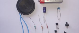
It is almost impossible to assemble a ticker on industrial-style LEDs without microcontroller programming skills and knowledge of data exchange protocols. Below is a simple diagram of a small LED display. If you are not afraid of difficulties and do not want to overpay for the finished product, you can purchase basic modules from which the product will be assembled.
But I would like to talk about a non-standard solution to a problem with minimal financial investment - how to make a ticker from LEDs using Arduino as a controller.
Schematic diagram of a creeping line on LEDs
The controller interacts through a special interface with external input devices. This could be a regular keyboard, a computer, or a smartphone. Based on the data obtained, a complete digital image matrix is formed, which is subsequently displayed on a board with indicators.
Self-assembly of a ticker can be done on an Arduino-based control module and several LED blocks on a max7219 controller.
The module consists of both a controller and a block of LEDs 8x8 elements. This element size is the minimum for displaying characters. The fact is that all dot matrix printers generated images for printing based on this format.
Where to buy spare parts?
Purchase drivers and LED chips from a store that sells equipment and components. You can view the range in online stores, select the parts you need and order home delivery. Now there are a lot of possibilities and components for any budget.
Some craftsmen assemble a structure from parts at a minimal cost. Some people order more expensive components. If you are going to make such a screen with your own hands, do not rush, put the components together carefully. In the store, the sales assistant will tell you which parts are more reliable, durable and better suited for the screen of your area.
Controller max7219
The max7219 controller is a 64-cell communication and memory interface unit for controlling LEDs. In memory, all data is stored in the form of a two-dimensional array.
Information is transferred via the SPI interface. SPI is a three-wire interface for two-way data transfer between devices. You can read more about how this interface works here.
To interact between the controller and the Arduino board, only three channels are used: DIN, CS, CLK.
You can connect up to four such LED modules to the standard connectors of the controller board, creating an 8 x 32 point display. To increase the number of connected segments, you can assemble a simple multiplexer that will switch control signals to the desired module. In this way, it is possible to display information on dozens of matrices. The operation of all LCD displays is based on this principle.
To facilitate the transfer of data flow to Arduino, there is a special library LedControlMS.
This is a video of an example of the library working with an LED display:
You can read more about controlling the matrix using a microcontroller at the link.
LED panels, controllers, or how to make an LED screen, part 1
It’s not for nothing that it was once said that appetite comes with eating. I can confirm 100%. I have already posted two reviews of LED panels, although it would be more correct to say one review and one addition. Today I will tell you about higher resolution LED panels, controllers, and communication with sellers. In general, brew coffee or tea, make yourself comfortable, the story will be long. Attention
, the review volume is very large, which can be critical for users with paid traffic. It would probably be more correct if I say that I ordered the panels and everything else not for myself, but for a friend, just like last time. He used the previous line and realized that he wanted more, and therefore this order was made. He was in charge of the selection of equipment, enclosures and installation; I was in charge of actually ordering all this, checking and trying to figure out what was what and how to manage it all. There were a lot of adventures, not all of them are over yet, but the bulk of the conclusions are already there, so we can safely talk about our epic with a new running line. In addition, I admit that there are some errors, since in fact this is only the second ticker that I am trying. And I only experimented for a few days. The review is an attempt to write down everything I learned along the way so I don't forget.
Firstly, it should be noted that in this case it is no longer just a “creeping line”, but a full-fledged configurable screen with the ability to display video; accordingly, the price tag in this case will also be different.
First, it’s worth saying why LED panels. 1. High brightness and contrast 2. You can set any size and proportions. 3. Normal operation even at low temperatures 4. Maintainability 5. User-friendly software 6. Autonomous operation (no PC)
But there are also disadvantages 1. Low resolution 2. High price.
Taking part in the review: 1. LED panels 64x64 pixels - 12 pieces with delivery cost 300 dollars (20.5 each panel + delivery) 2. HD-D10 controller (about 30 dollars excluding delivery) 3. HD-D30 controller (about 40 dollars excluding delivery) 4. Two power supplies 5 Volt 40 Ampere, bought offline, for about 13 bucks.
Total without taking into account the material for the cases, glass, temperature sensor and other small items - $400.
The controllers were ordered first, since I tried to promote the panel seller for a discount, since the order amount was quite large. In general, nothing worked out with the discounts and about a week later he sent me the panels. But they arrived about a week earlier than the controllers; in total, delivery took about 10 days. I received two rather large parcels, wrapped in such a way that they could easily be used to play football or be used as a pillow. The second photo shows how much packaging material came out.
The panels were ordered in exactly two parcels due to customs restrictions, but at the same time they were packed differently inside. In one parcel there were simply 6 panels lined with soft material, in the second they were sealed in pairs in plastic and also additionally padded to prevent damage. Perhaps this difference immediately tensed me up and my premonition did not deceive me.
In total it turned out to be a rather impressive stack of panels with a bunch of different wires.
Let's start with the scope of delivery. Each package contained 6 cables for connecting information lines and three power cables, as well as a small pile of plastic. In total there are 12 cables and 6 power cables.
1, 2. Power cables are standard for such panels; on one side there are two crimped ends for connection to the power supply, on the other there are two connectors for connecting to the panels. 3. The cables are about 10-12cm long, one was broken, it’s good that there was some stock left over from the previous panels and I didn’t have to go to the market. 4. A bunch of plastic debris fell out of the first bag (where the panels were separate). Most of them are pins along which the panels are oriented when installed on the frame. They stuck out and were broken during transportation. Since we didn’t need them, we simply abandoned them.
But in addition to the pins, the cable clamps on the cables were also broken; this is also tolerable, although less pleasant. On the left is a normal cable, in the middle without a latch at all, on the right with a broken latch.
And here is the panel. But first, it’s worth explaining how the panels generally differ.
Form
No matter how trite it sounds, the most common shapes are rectangle or square. Moreover, often the rectangle has such dimensions that its long side is exactly twice as large as its short side, i.e. it's essentially two squares.
I talked about rectangular panels in the previous review, but this time I bought square ones.
Dimensions
. Well, everything here is generally extremely simple, the key size, oddly enough, is the thickness of the panel, since the length and width are calculated based on the resolution and pixel size. Since our pixel size is 3mm, and the resolution is 64x64, it turns out 64x3=192mm, the panel is square, so the size is 192x192mm.
Brightness
Sometimes it is indicated by sellers “out of the blue”, although it is quite significant. External panels are usually brighter than internal panels. Naturally, they consume more energy.
Protection
The panels come in external and internal versions. For the outside, the panel is covered with a protective compound like silicone, which prevents moisture from reaching the contacts of the LEDs and the board.
In addition, LEDs are often covered with a small visor on top to protect from the sun. These visors are visible on the left side of the photo, and I will also show them in other photos.
But since it was planned to use the panel indoors, and even in a housing, it was decided to buy “defenseless” panels, especially since they are usually cheaper.
LED type
SMD or DIP. In large panels, especially outdoor ones, LEDs are sometimes used in a conventional design, with leads. True, such LEDs have some disadvantages, which are rarely discussed. These LEDs have a lens on the front that can focus sunlight onto the LED crystal, thus burning out the crystal. Therefore, in my opinion, open-frame models are more reliable. By the way, large protective visors are visible here.
In our case, a panel with SMD LEDs.
Before I move on to a more detailed description of the panels, I’ll tell you about the other features.
Pixel
Square or rectangular. The panel with a square pixel is included in the review, and I will show the rectangular one separately. Most often these are inexpensive, low-resolution models. More suitable simply as advertising signs.
Color
One-color, two-color, three-color (RGB or full color). In addition, there are panels with four LEDs per pixel, most often an additional red LED is used, since red color accounts for the bulk of the power consumption, I will show this later. I specifically selected a photo with ordinary LEDs, not SMD, in my opinion it’s more clear, since if the LED is SMD, then more often than not it has the same body, common for all colors. Single-color panels are used where bright, cheap and visually appealing is needed. Full-color panels are well suited for displaying not only photos, but also as video walls.
Pixel size
Oh, here you can actually break your head, since the choice of pixel sizes is not just large, it is gigantic. For square pixels this is usually P37.5, P31.25, P25, P20, P16, P12.5, P10, P8, P7.625, P6.26, P6, P5.95, P5, P4.81, P4, P3 .91, P3, P2.5, P2, P1.9, P1.6 and even P1.25. The number after the letter P means the pixel size in mm, for example P4 has a size of 4x4mm, but there is also a double marking, for example P10 P16, meaning a rectangular pixel 10x16mm. Some of these sizes are found less frequently, some more often. The minimum that I saw on sale (although I didn’t specifically look for it) was P2 with a 2x2mm pixel. For large screens, choose a larger pixel, for small ones, correspondingly smaller ones. By big screens I mean these
Or even those in the form of a ceiling. In general, the size of the screen is actually limited only by the budget; moreover, LED screens can not be flat at all, but have any shape, be it spherical, concave, or wavy.
The most common module options.
Number of pixels.
Vertically, usually 8, 16, 24, 32, 64. Horizontally, there is more choice, 16, 32, 64, 96, 128, 160, 192. Perhaps they come with a larger number.
Some of the information can be seen in the sign, as well as below under the spoiler.
More information about resolution, sizes and panel options
Scan mode
Since the information is updated dynamically, there are several modes - 1/32, 1/16, 1/8, 1/4. I've only come across the 1/16 and 1/32 options. I may be mistaken about this point, but as far as I understand, panels with a vertical number of 64 pixels are organized in two by 32, therefore they have a 1/32 scanning, but they do not work with all controllers, although I got ahead of myself. Above there is a table where, in addition to photographs and indicating the resolution, there is also information about the scanning mode. An important point here is that your controller must support this mode as a panel. Usually simple models can only do 1/4, 1/8 and 1/16, more complex ones can do 1/32.
Execution of the module itself.
Most often, a module is a finished product. In fact, this is a printed circuit board with LEDs on one side and control electronics on the other. In some cases, the plastic frame can be quite solid, and in the case of an external version, it also has additional seals.
But in some cases they also make an aluminum frame, especially if the module sizes are large; plastic simply cannot withstand this.
In our case, there was probably the simplest option, a light plastic frame with metal nuts, with which the modules are attached to the common frame.
A standard four-pin connector is installed to connect the power; these are the ones found in many types of matrices.
Since in many cases the panels are pass-through, there are two connectors for connecting the data bus. Near the connectors there are marks indicating the signal path and, accordingly, the order in which the panels are connected.
As before, the board contains control chips, LED drivers and shift registers. If I'm not confused, then they are the same, only in larger quantities.
Like last time, the body of the panels is not rectangular in cross-section, but more like a trapezoid. This is necessary in order to be able to join the panels to each other at zero or even with a slight curvature, for example, to “wrap” cylindrical surfaces with them, although the radius will be quite large.
If you connect two panels, it will look something like this. Then we simply connect the required number of panels into a line and obtain the required horizontal size. Vertically everything is even simpler, the next “line” is simply connected to the next output of the control controller. But we must take into account that you can increase the number of panels (especially in length) up to a certain value, then you will either have to stop or reduce the frequency of updating information.
As I already wrote, the order included 12 P3 panels with a resolution of 64x64 pixels. They were intended not for one screen, but for two. But if you add them all together, you can get a screen with a size of about 600x800 mm (1 meter or 39 inches diagonally) and a resolution of 256x192 pixels. To make a FullHD display based on such panels, you will have to use 30x17=510 panels, and the screen will have dimensions of 5.76x3.26 meters. For example, the largest wall in the hall of a typical apartment measures 6x2.65 m.
Naturally, the dimensions are large, but there are panels with a fine pixel pitch that allow you to display a very high-quality image.
The panels were received first and a friend brought the Onbon bx-5ql controller, which was used last time, to check. At first I wanted to check one by one, but a friend suggested checking 4 pieces at a time to speed up the process. 1. We assembled a construction set from a power supply, a controller and four panels and began testing.
The first thing we saw was that the panel controller does not completely illuminate, but only the second and fourth quarter of the horizontal. Of course, this controller is not intended for such panels, so in principle I took it calmly.
2,.3. But when I decided to take a photo “for history,” I accidentally noticed something strange. We checked the third (last) four panels and it included two panels from one parcel and two from the second. My friend noticed the difference, and then I noticed the difference. The color of the picture is different. Okay, let's just turn on the single-color mode and it looks like two colors, green and blue, are mixed up. By opening our own review and looking at the order in which the controller displays colors in the test, we figured out which panels were not working correctly. 4. Just in case, we swapped the outer panels, the problem was confirmed, the panels from one parcel display the color incorrectly. Moreover, red and white are displayed correctly, which is quite understandable.
I immediately wrote to the seller about all this, to which I received an answer - what controller was used? Answered that Onbon bx-5ql. The seller responded by saying that he was using a different type of controller.
Well, okay, it’s different, so we decided to wait for the normal controllers for now, and then decide what to do, maybe the problem really isn’t in the panels.
On the left is a panel that displays the color correctly, on the right with green and blue mixed up. At the very beginning, I wrote that some of the panels were sealed in plastic, so these were normal panels. In addition, the panels also differ in appearance, with more fastening points.
There are also some differences in the board layout and element base.
By the way, the last time we bought additional panels for the first line, we also received panels of a different version, but then this did not cause any problems.
Another photo of the components, just in case, might come in handy.
About a week later the controllers arrived, but first I’ll tell you a little about why they are needed and what they are.
As is already clear from the description, unlike monitors, LED panels themselves cannot display anything, since they are essentially just LED matrices without a controller. Controllers can range from relatively simple ones, with a small amount of memory, to quite advanced ones, although they remain just an extended version of simple ones. Some controllers can also output sound.
Loading control programs can be done not only through the COM port or USB drive, but also via Ethernet, WiFi and even GSM.
Like a fairly large number of modern systems, work via the “cloud” is also supported.
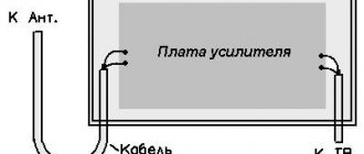
In addition to stand-alone controllers, which can work on their own, there are also those connected to a computer. In this case, a special board is installed in the computer, onto which the signal from the monitor is input, and the board already outputs a control signal for the panel controller.
The control circuit in this case looks like this.
There are generally “monster-like” options, but they are unlikely to be needed by ordinary users.
You might ask why some boards have two Ethernet connectors. When creating large screens, control boards can be connected in series. But if in previous versions the boards worked asynchronously, since they controlled only one screen, then in this case the synchronous operating mode is used. Each controller displays its section of the image synchronously with the other controllers.
The controllers were ordered from another seller, shipped by Nova Poshta, no complaints about the packaging. Each controller is packaged in a separate package with a controller brand label.
The entire purchased set is: 1. HD-D10 controller - link, price including delivery $33.96. 2. HD-D30 controller, link, price including delivery $45.63. 3. The second controller is equipped with a hub for connecting panels. 4, There were also two CDs with software, and the color of the disc matches the color of the sticker on the controllers, very thoughtfully.
Since the controllers belong to the same series, they have a common description. In general, there is also a D20 variant, but for some reason it was not included in the description, maybe for the better, so as not to confuse. As you can see, the difference is not that big.
If you compare this controller with the previous Onbon bx-5ql, you will immediately notice the size of the board, as well as the ability to connect to a local network. But in fact, the differences are much greater, and if you have tried something like the D10-D30, not to mention the more advanced models of the C series and especially the A series, then you will not want to go back. but more on that later.
First, let's look at the younger version of the board, D10.
At the end of the board there is a power terminal block, as well as a connector for connecting to a local network and a USB for a flash drive.
On the other side of the board there are four connectors for connecting LED panels. Since there are four connectors, it is quite possible to connect four lines that can work synchronously.
Like other models, the board has space for connectors for additional devices, a button to turn on the Test mode, and a battery for the built-in clock. There are also two LEDs indicating the operating mode.
1. On top of the board there is a place for the WiFi module connector. 2. Below is a place for the GSM module. 3. Near the connectors for connecting panels there is an LED indicating operation of the panels. 4. For power protection, a self-resetting fuse is installed at the input.
Everything is controlled by a processor with hieroglyphs in the markings. As far as I know, it is based on the Cortex ARM A9 core. The radiator is glued to the top, but I didn’t remove it, partly because it needs to be glued in place later, partly because there’s really no point in it. The radiator is quite hot during operation.
1. In addition, Altera Cyclone IV is installed on the board. I suspect that it is she who outputs the signal to the panel. 2. The heatsink on the processor is glued in an interesting way, offset and not in the center. and it's the same on both boards. 3. Flash memory from Micron. The volume is supposedly 2 GB. 4. 256 MB RAM. 5. 2M x 16 Bit x 4 Banks Synchronous DRAM chip, I don’t quite understand its purpose here, I’ll assume that this is a separate RAM for Altera. 6. Real time clock, it’s strange that it’s so far from the battery.
1. Ethernet controller 2. Bidirectional buffers for connecting the panel data bus. 3. LT8619, HDMI/MHL Dual-mode Receiver 4, 5, 6. Power converters for various nodes.
The second board looks almost the same, with the exception of some minor differences.
Moreover, from below there are no differences at all.
Exactly the same connectors, even the location is identical. There is also a place on the left for sealing the WiFi antenna connector.
And since the boards are very similar, then I will simply provide comparative photos and describe the differences. First of all, the markings, as well as a slight difference in the location of some components. Although at first glance it seemed that everything was identical, even the sizes of the boards.
From below, the differences are even less noticeable.
Perhaps the most important difference is the presence of an mPCI slot; the previous board only had space for it.
I tried one of my WiFi modules, but it refused to work, especially since it clearly doesn’t fit in length, and it simply won’t be possible to secure it. An SSD in this slot will definitely not work, but the size is just right. But again, even if you buy a WiFi module of the appropriate size, it most likely will not work; I suspect that there are drivers only for some models. If you need WiFi, then you need to buy it with it.
Like the previous model, the output on the panel is controlled by Altera Cyclone 4.
But the output on the panel is organized somewhat differently; here one common connector is used, the signal to which is output through the same 74HC245 buffers.
To connect the panels you need to use a hub or splitter, whichever is convenient for you. This played a role when choosing a product, since often the hub is not included in the kit and must be purchased separately. Here the hub is sold together with the controller.
The hub board also contains 74HC245 buffer amplifiers, so this is not just an adapter from a 50-pin connector to a 4x16 pin. By the way, above in the screenshot with the characteristics of the board there is a plate with the assignment of the connector contacts.
That's exactly the disadvantage of such a design, it's the high altitude. There is an option to use a cable instead of direct connection, but it is better to buy it together with the board, since offline it is not always possible to buy a “male” that is crimped onto the cable. As an option, crimp the 50-pin connector, and solder the hub board to the cable.
As far as I know, the vast majority of panels are powered by 5 Volts, as are the controllers. Therefore, a 5 Volt 40 Ampere power supply was purchased for the project. Yes, the currents are large here, nothing can be done. The second power supply was purchased after a successful test of the first. In our case, the power supply will be located separately. In this option, it is necessary to use wires with a large cross-section and short length. An alternative option is to install a 12/24-5 Volt converter inside the panel and power the entire structure from a 12 or 24 Volt power supply. The goal of moving the power supply outside was twofold: less heating of the panel and less thickness of the case.
Since the store gave a one-year warranty on the power supply, I didn’t open it, I looked through the holes in the case. And to be honest, I didn’t really like what I saw. The capacity of the output capacitors is 6600 μF (3x2200), the inductor is not very large, and at a load above 40-50% it rings noticeably, which is very annoying. And the overall quality is very dismal; all this is compensated only by the low price and the presence of a guarantee.
Initially, the plan was to make one review, but since it began to grow greatly, I decided to make some kind of conditional division into hardware and software. In addition, in my opinion, it is more convenient to separate comments. In general, the continuation is here.
Interface for entering information for subsequent output to the LED matrix
In order to change the displayed text at your discretion, you will need an information input device.
Ways to transfer information to the Arduino controller:
- via a keyboard with a PS2 interface;
- via software keyboard;
- via smartphone.
There are many options for exchanging data with the controller board, in addition to the standard connection to a computer via the ICP protocol.
The Arduino IDE shell has a built-in library for working with the PS2 keyboard. You can use software modules to work with a standard eight-button Arduino keyboard. The input organization is built on the principle of mobile phones, when several characters are “suspended” on one button. By connecting a bluetooth module to the Arduino board, it is possible to transmit test information via a smartphone.
When you understand the organization of the ticker on standard Arduino modules, you can move on to the next stage.
Firmware
To flash the ATtiny2313 MK firmware, you should use a homemade programmer connected to the computer’s RS-232 and known to many as PonyProg2000. Before flashing the firmware, you must set the fuses in accordance with the table.
Firmware for running lights on ATtiny2313 can be downloaded here.
Arduino and industrial solutions
The same addressing principles are used to create larger LED displays.
Outdoor LED panels will require more powerful light sources than a miniature LED display. max7219 are used as image output controllers , and a power driver on a ULN2803 . It has eight control signal switching lines, which is ideal for our purposes.
In the design of large-sized advertising displays, super-bright LEDs with a luminous flux of 70-100 lm are used.
In single-color (monochrome) LED matrices, each element has two states: on/off. To transmit full-color information, RGB LEDs with PWM brightness control controllers for each color are used.
Please rate the article. We tried our best:)
Did you like the article? Tell us about her! You will help us a lot :)
Formulation of the problem
The objective of the project is to produce a sports timer for a mini-football tournament.
The dimensions of the field are 20 x 40 meters - based on this, it was decided to make the timer numbers no less than 100 mm high, using ultra-bright LEDs.
The timer should count down the time (for example, 20 minutes) of one of the two halves of a football match, and then simply stop until the restart button is pressed. It is also necessary to provide a button to stop the time countdown when the match is stopped in the middle of the half. At the end of the half, you must sound a sound signal, which should be heard by the commentator sitting next to you.
PCB Description
The printed circuit board was laid out in the Altium program and made of double-sided foil fiberglass with a thickness of 1.5 mm (I recommend taking 2 mm). On one side, LEDs, their limiting resistors, and power switches are soldered, and on the other, control chips and a piezo speaker are soldered. The marking of LEDs is indicated differently in the documentation everywhere - I didn’t check my LEDs for polarity at first and soldered them in reverse, according to the first documentation I came across. I then had to solder them with a hairdryer and turn them over.
Sports timer design
The body was made of MDF board. Ventilation holes are drilled on the sides, and simple mini-buttons are stuck on top.
The front part of the timer was covered with plexiglass and sealed with car tinting (several layers depending on the darkening power of the film).
The controller was powered from a battery in order to avoid resetting the time if the power supply from the mains supply was inadequate (but we will not consider the power circuit here).
The modules and battery were glued with liquid nails.
The first button starts and stops the time countdown, the second is a reset button to zero. The third button enters the match time setting mode. In this mode, you can use the two right buttons to add or decrease the time of the half of a football match in minutes.
Bluetooth connection
The first step is to install the free Bluetooth spp pro application on your smartphone or tablet.
After pairing, you need to configure the application buttons. Here are some configuration examples:
Btn name: RED Send val: (100)Scrolling . . . Btn name: GREEN Send val: (200)Scrolling . . . Btn name: ORANGE Send val: (300)Scrolling . . . Btn name: RED* Send val: (100)* Btn name: GREEN* Send val: (200)* Btn name: ORANGE* Send val: (300)* Btn name: Speed Up Send val: (00>)* Btn name: Speed Down Send val: (00<)* Btn name: Dimmer Send val: (0<0)* Btn name: Brighter Send val: (0>0)* Btn name: Amperkot Send val: Powered by Amperkot
After this, the creeping line is completely ready for use. You can send any text to be displayed on it.
If desired, based on this project, you can create a running line of any length. If 7 matrices are too many, the line can be easily shortened.
The article is the author's translation from the website instructables.com.
This article is the property of Amperkot.ru. When reprinting this material, an active link to the original source, not closed for indexing by search engines, is required.
Scoreboard for hockey box (hockey scoreboard)
The scoreboard is designed to display (visualize) information about the game score, period number, remaining game time, time of one penalty for each team.
The entire device consists of a scoreboard, a control panel and a radio remote control (originally made so that it could be controlled by a referee from the field).
Characteristics
220V
- Power consumption no more than 350W
- The range from which information is readable is up to 50 m
- Dimensions of count indicators 30x15cm
- Dimensions of period and game time indicators: 20x10cm
- Dimensions of penalty time indicators: 10x5cm
- Scoreboard dimensions HxWxD 80x122x11 cm
- Radio remote control range 20 m
- Weight no more than 10 kg