Register Login
Publication date: November 12, 2019
In 1816, Reverend Robert Stirling, seeking to create a safer alternative to steam engines, whose boilers often exploded due to high steam pressure and the primitive materials available at the time, invented a new device. Like other similar units, the Stirling engine converts thermal energy into mechanical energy. Its significant feature is that it is a type of external combustion engine. This means that it uses a fixed amount of working fluid, usually air, and the heat it consumes is supplied from the outside. This allows the device to operate on virtually any heat source, including fossil fuels, hot air, solar, chemical and nuclear energy. It can also handle very low temperature variations.
How to make your own Stirling engine.
How to make a Stirling engine.
Explanation of the operation of the Stirling engine.
We start by marking the flywheel.
Six holes failed. It turns out not beautiful. The holes are small and the body between them is thin.
In one go we sharpen the counterweights for the crankshaft. The bearings are pressed in. Subsequently, the bearings are pressed out and an M3 thread is cut in their place.
I milled it, but you can also use a file.
This is part of the connecting rod. The rest is soldered with PSR.
Working with a reamer over the sealing washer.
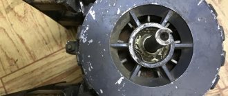
Drilling the Stirling bed. The hole that connects the displacer to the working cylinder. 4.8 drill for M6 thread. Then it needs to be turned off.
Drilling the working cylinder liner for reaming.
Drilling for M4 thread.
How it was done.
Dimensions are given taking into account the conversion. Two pairs of cylinder-piston, 10mm, were made. and by 15mm. Both were tested. If you set the cylinder to 15mm. then the piston stroke will be 11-12mm. and it doesn't work. But 10mm. with a stroke of 24mm. just right.
Dimensions of connecting rods. Brass wire Ф3mm is soldered to them.
Connecting rod mounting assembly. The version with bearings did not work. When the connecting rod is tightened, the bearing is deformed and creates additional friction. Instead of a bearing I made Al. bushing with bolt.
Dimensions of some parts.
Some dimensions for the flywheel.
Some sizes of how to mount on the shaft and joints.
We place a 2-3mm asbestos gasket between the cooler and the combustion chamber. It is also advisable to place paronite gaskets or something that conducts less heat under the bolts that hold both parts together.
The displacer is the heart of Stirling; it must be light and conduct little heat. The stock was taken from the same old hard drive. This is one of the linear motor guides. Very suitable, hardened, chrome plated. In order to cut the thread, I wrapped a soaked rag around the middle and heated the ends until red hot.
Connecting rod with working cylinder. Total length 108mm. Of these, 32mm is a piston with a diameter of 10mm. The piston should move into the cylinder easily, without noticeable scuffing. To check, close it tightly with your finger from below, and insert the piston from above, it should release down very slowly.
I planned to do this but made changes during the process. In order to find out the stroke of the working cylinder, we move the displacer into the refrigerating chamber, and extend the working cylinder by 25 mm. We heat the heat chamber. We carefully place a ruler under the working connecting rod and remember the data. We push the displacer sharply, and how much the working cylinder moves is its stroke. This size plays a very important role.
View of the working cylinder. Connecting rod length 83mm. The stroke is 24mm. The handwheel is attached to the shaft with an M4 screw. His head is visible in the photo. And in this way the counterweight of the displacer connecting rod is attached.
View of the displacer connecting rod. The total length with the displacer is 214 mm. Connecting rod length 75mm. Stroke 24mm. Pay attention to the U-shaped groove on the flywheel. Made for power take-off. The idea was either a generator or through a pin to the cooler fan. The flywheel pylon has dimensions 68x25x15. The top part is milled on one side to a depth of 7mm and a length of 32mm. The center of the bearing from the bottom is at 55mm. Fastened from below with two M4 bolts. The distance between the centers of the pylons is 126mm.
View of the combustion chamber and cooler. The engine housing is pressed into the pylon. The dimensions of the pylon are 47x25x15, the recess for landing is 12 mm. It is attached to the board from below with two M4 bolts.
Lamp 40mm. in diameter height 35mm. Recessed into the shaft by 8mm. At the bottom in the center there is an M4 nut sealed and secured with a bolt from below.
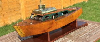
Finished look. Oak base 300x150x15mm.
I've been looking for a working scheme for a long time. I found it, but it was always due to the fact that either there was a problem with the equipment or with the materials. I decided to make it like a crossbow. After looking at many options and figuring out what I had available and what I could do myself with my own equipment. I didn’t like the dimensions that I immediately figured out when the device was assembled. It turned out to be too wide. I had to shorten the cylinder frame. And the flywheel should be placed on one bearing (on one pylon). The materials of the flywheel, connecting rods, counterweight, sealing washer, lamp and working cylinder are bronze. The pylons, working piston, cylinder frame cooler and washer with threads from the heat chamber are aluminum. Flywheel shaft and displacer rod steel. Stainless steel combustion chamber. Graphite displacer. And I’ll put it on display for you to judge.
Source: zaryad.com
Layout of cylinders in a double range.
The figure shows two “hot” cylinders in which the displacers are located. They operate in different directions with a phase shift of 180°. To simplify the operating diagram, the regenerator is not indicated in the figure. The red lines indicate the heating areas of the cylinders (heater), and the blue lines indicate the cooling areas (refrigerator).
Below in the center is a working cylinder with a working piston. Depending on the position of the displacers, it can take the values of top dead center (TDC) or bottom dead center (BDC). In order not to overload the circuit, I deliberately omitted the drive mechanics. It can be chosen at the discretion of the developer himself.
Powerful DIY Stirling engine
The Stirling engine, once famous, was forgotten for a long time due to the widespread use of another engine (internal combustion). But today we hear more and more about him. Maybe he has a chance to become more popular and find his place in a new modification in the modern world?
The Stirling engine is a heat engine that was invented in the early nineteenth century. The author, as is clear, was a certain Stirling named Robert, a priest from Scotland. The device is an external combustion engine, where the body moves in a closed container, constantly changing its temperature.
Due to the spread of another type of motor, it was almost forgotten. Nevertheless, thanks to its advantages, today the Stirling engine (many amateurs build it at home with their own hands) is making a comeback again.
The main difference from an internal combustion engine is that the heat energy comes from outside, and is not generated in the engine itself, as in an internal combustion engine.
Efficiency
The efficiency of the temperature difference in the engine can reach about 70%. For the Carnot cycle on the graph, the efficiency is as follows.
Basically, the car was equipped with a 4-cylinder Stirling engine; it was installed at the beginning of the 20th century and gave an efficiency of 35.
The American automobile company Mechanical Technology Inc (Mecanical Technology Incorporated) creates Stirling engines. Their internal combustion engines provide an efficiency of 43.5%.
Principle of operation
You can imagine a closed air volume enclosed in a housing with a membrane, that is, a piston. When the housing heats up, the air expands and does work, thus bending the piston. Then cooling occurs and it bends again. This is the cycle of operation of the mechanism.
It is no wonder that many people make their own thermoacoustic Stirling engine at home. This requires the bare minimum of tools and materials, which can be found in everyone’s home. Let's look at two different ways to easily create one.
What to do if the homemade product does not work?
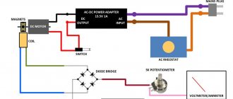
If suddenly you have assembled a perpetual electric motor with your own hands, but it does not rotate, do not rush to get angry. The most common cause of a motor not spinning is excessive distance between the magnet and the coil. In this case, you just need to slightly trim the legs that hold the rotating part.
This is the whole technology for assembling a homemade magnetic electric motor at home. If you watched the video tutorials, you were probably convinced that you can make a motor with a battery, a copper wire and a magnet with your own hands in different ways. We hope you found the training interesting and useful!
How to do
A firebox and two cylinders for the base are prepared from tin, of which the Stirling engine, made with your own hands, will consist. The dimensions are selected independently, taking into account the purposes for which this device is intended. Let's assume that the motor is being made for demonstration. Then the development of the master cylinder will be from twenty to twenty-five centimeters, no more. The remaining parts must adapt to it.
At the top of the cylinder, two protrusions and holes with a diameter of four to five millimeters are made to move the piston. The elements will act as bearings for the location of the crank device.
Next, they make the working fluid of the motor (it will become ordinary water). Tin circles are soldered to the cylinder, which is rolled into a pipe. Holes are made in them and brass tubes from twenty-five to thirty-five centimeters in length and with a diameter of four to five millimeters are inserted. At the end, they check how sealed the chamber has become by filling it with water.
Next comes the turn of the displacer. For manufacturing, a wooden blank is taken. The machine is used to ensure that it takes the shape of a regular cylinder. The displacer should be slightly smaller than the diameter of the cylinder. The optimal height is selected after the Stirling engine is made with your own hands. Therefore, at this stage, the length should include some margin.
The spoke is turned into a cylinder rod. A hole is made in the center of the wooden container that fits the rod, and it is inserted. In the upper part of the rod it is necessary to provide space for the connecting rod device.
Connection
Connecting a mini-motor made by yourself is carried out according to a certain scheme.
The main attention is paid to the number of drive wires, as well as the purpose of the device. Stepper motors can be equipped with 4, 5, 6 or 8 wires
The modification with four wiring elements can be used exclusively with a bipolar device. Any phase winding has two wires. To determine the required connection length in a step-by-step mode, it is recommended to use a regular meter, which allows you to accurately set the required parameter.
The powerful six-wire motor has a pair of wires for each winding and a centering tap that can be connected to a mono or bipolar device. For aggregation with a single device, all six wires are used, and for a paired analogue, one end of the wire and the central tap of each winding will be sufficient.
How to do
Foam rubber is very often used to make a simple, low-power Stirling engine at home with your own hands. A displacer for the motor is prepared from it. Cut out a foam circle. The diameter should be slightly smaller than that of a tin can, and the height should be slightly more than half.
A hole is made in the center of the cover for the future connecting rod. To ensure that it runs smoothly, the paper clip is rolled into a spiral and soldered to the lid.
The foam circle is pierced in the middle with a thin wire and a screw and secured on top with a washer. Then the piece of paper clip is connected by soldering.
The displacer is pushed into the hole in the lid and connected to the can by soldering to seal it. A small loop is made on the paperclip, and another, larger hole is made in the lid.
The tin sheet is rolled into a cylinder and soldered, and then attached to the can so that there are no cracks left at all.
The paperclip is turned into a crankshaft. The spacing should be exactly ninety degrees. The knee above the cylinder is made slightly larger than the other.
The remaining paper clips are turned into shaft stands. The membrane is made as follows: the cylinder is wrapped in polyethylene film, pressed and secured with thread.
The connecting rod is made from a paper clip, which is inserted into a piece of rubber, and the finished part is attached to the membrane. The length of the connecting rod is made such that at the lower shaft point the membrane is drawn into the cylinder, and at the highest point it is extended. The second part of the connecting rod is made in the same way.
One is then glued to the membrane and the other to the displacer.
The legs for the jar can also be made from paper clips and soldered. For the crank, a CD is used.
Now the whole mechanism is ready. All that remains is to place and light a candle under it, and then give a push through the flywheel.
Stirling engine power plants - simplicity, efficiency and environmental safety
Ecology of consumption. Science and technology: The Stirling motor is most often used in situations where an apparatus for converting thermal energy is required, characterized by simplicity and efficiency.
Less than a hundred years ago, internal combustion engines tried to gain their rightful place in the competition among other available machines and moving mechanisms. Moreover, in those days the superiority of the gasoline engine was not so obvious. Existing machines powered by steam engines were distinguished by their quietness, excellent power characteristics for that time, ease of maintenance, and the ability to use various types of fuel. In the further struggle for the market, internal combustion engines, due to their efficiency, reliability and simplicity, gained the upper hand.
The further race to improve units and driving mechanisms, which gas turbines and rotary types of engines entered in the mid-20th century, led to the fact that, despite the supremacy of the gasoline engine, attempts were made to introduce a completely new type of engine onto the “playing field” - thermal, for the first time invented back in 1861 by a Scottish priest named Robert Stirling. The engine received the name of its creator.
Sleeving procedure
According to experts, lining an automobile engine block is possible for any internal combustion engine. That is, various motors are subject to such repairs.
Masters usually know which engines are initially lined at the auto production stage, that is, lined from the factory, and which are positioned as unrepairable. Since we have figured out that all types of internal combustion engines can be repaired, the presence or absence of liners from the factory does not play a decisive role.
If the block was lined at the factory, then most often we are talking about wet sleeves. The repair consists of replacing the worn bushing with a new one. This is the simplest sleeve option among all existing ones. In some cases, work is carried out manually. To do this, it is enough to select the necessary and suitable repair sleeves.
It is also a mistake to assume that when lining, absolutely all bushings must be replaced. This directly depends on which of them are worn out. Only those that have already used up their resource can be replaced. The rest remain in their places and are used until they become scuffed and damaged.
If you have an unlined block in front of you, that is, the engine from the factory does not provide for the use of sleeves in its design, and dry sleeves should be selected for it, this task becomes noticeably more difficult.
- Bushings made from alloy cast iron are mounted in cast iron blocks;
- If the block is made of aluminum alloy, then aluminum bushings should be used.
We must not forget that alloys for BC can have various additives and additional components. Also, special reinforcing materials are applied to the walls themselves, which provides improved resistance to damage and scuffing. Therefore, it will be better if a qualified specialist undertakes the selection of cartridges.
Sleeving can be divided into the pressing process and hot sleeving.
Press-fitting is used in situations where it is necessary to replace old liners with new bushings. Here it is necessary to pre-bore the cylinders in order to create a perfectly even and correct geometry for seating new liners. Even the slightest deviation during boring is not allowed. Otherwise, the pistons and their rings will not be able to function normally. After boring, the bushings are pressed in, the corresponding pistons are installed, and the engine is assembled.
In the case of hot sleeves, when a dry sleeve is mounted, the process looks like this:
- The BC is heated to approximately 150 degrees Celsius;
- before installation, the selected sleeve is cooled using liquid nitrogen;
- a solution is applied to the sleeve to prevent condensation from forming during the installation of the cold sleeve inside the hot block;
- the sleeve is inserted into its prepared place.
This method of restoring the BC is optimal in terms of quality, since the technology makes it possible to create a tight fit and ensure tension in the areas where the bushing and block come into contact. The bushing itself easily slides into place, literally under its own weight. To completely install it in the socket, the master just needs to knock a little with a hammer. There is no need to use any extra force for pressing in the case of hot sleeves. Unlike the first method discussed, replacing the old bushing with a new one.
But there are some exceptions when the aluminum BC is not pre-bored. Then the bushing is installed by pressing. The procedure differs in that before installation the socket under the sleeve is lubricated with sealant. And then a new element is pressed in.
In practice, everything looks much more complicated. That is why lining should be trusted exclusively to highly qualified specialists with extensive experience, knowledge and relevant skills. It is not recommended to try to sleeve the BC with your own hands. Without special tools and equipment, it is almost impossible to do this efficiently.
If you follow the rules, follow all recommendations and strictly take into account all the technological features of the liner, the minimum service life of the internal combustion engine can be extended by 100 thousand kilometers. But in some cases, cars easily overcome marks of 150-200 thousand kilometers, while properly maintaining and operating the engine.
STIRLING ENGINE: PHYSICAL SIDE OF THE ISSUE
To understand how a tabletop Stirling power plant works, you need to understand a general understanding of the operating principles of heat engines. Physically, the principle of operation is to use mechanical energy, which is obtained when gas expands when heated and its subsequent compression when cooled. To demonstrate the principle of operation, we can give an example based on an ordinary plastic bottle and two pans, one of which contains cold water, the other hot.
When lowering the bottle into cold water, the temperature of which is close to the temperature at which ice forms and the air inside the plastic container is sufficiently cooled, it should be closed with a stopper. Further, when the bottle is placed in boiling water, after some time the cork “shoots” with force, since in this case the work done by the heated air was many times greater than that done during cooling. If the experiment is repeated many times, the result does not change.
The first machines that were built using the Stirling engine accurately reproduced the process demonstrated in experiment. Naturally, the mechanism required improvement, which consisted in using part of the heat that the gas lost during the cooling process for further heating, allowing the heat to be returned to the gas to accelerate heating.
But even the use of this innovation could not save the situation, since the first Stirlings were large in size and had low power output. Subsequently, attempts were made more than once to modernize the design to achieve a power of 250 hp. led to the fact that in the presence of a cylinder with a diameter of 4.2 meters, the actual power output produced by the Stirling power plant of 183 kW was in fact only 73 kW.
All Stirling engines operate on the principle of the Stirling cycle, which includes four main phases and two intermediate ones. The main ones are heating, expansion, cooling and compression. The transition stage is considered to be the transition to the cold generator and the transition to the heating element. The useful work performed by the engine is based solely on the temperature difference between the heating and cooling parts.
Inspired by Philips MP1002C
In the mid-80s, I had the pleasure of witnessing testing of a Philips MP1002C generator set that actually worked. The experience made a deep impression on me, especially in how calmly the Stirling started up and came to life. The maximum noise came from the burner (combustion chamber), but ultimately the Philips engine produced a very pleasant sound background - all that needed to be replaced were the noisy bearings.
As the old saying goes, “It worked and worked like a Singer sewing machine!” At the time, my experience with Stirling engines consisted of designing a few bench-top sized models, but after seeing and hearing a Philips engine in action, I wanted to design, design and build an engine of the same caliber...make something large enough that it would produce a useful, perceptible work.
MODERN STIRLING CONFIGURATIONS
Modern engineering distinguishes three main types of such engines:
- alpha stirling, the difference of which is two active pistons located in independent cylinders. Of all three options, this model has the highest power, having the highest heating piston temperature;
- beta stirling, based on one cylinder, one part of which is hot and the other cold;
- Gamma Stirling, which in addition to the piston also has a displacer.
The production of the Stirling power plant will depend on the choice of engine model, which will take into account all the positive and negative aspects of such a project.
The price of being methodical
When you learn about an old technical idea that has been revived in modern technology, the question immediately arises: what prevented its implementation before? What was that problem, that “clue”, without solving which she could not make her way into life? And it almost always turns out that an old idea owes its revival either to a new technological method, or to a new design that predecessors had not thought of, or to a new material. The external combustion engine can be considered a rare exception. Theoretical calculations show that the efficiency "Stirling" and "Erickson" can reach 70 percent - more than any other engine. This means that the failures of their predecessors were explained by secondary, in principle removable factors. The correct choice of parameters and areas of application, a scrupulous study of the operation of each unit, careful processing and fine-tuning of each part made it possible to realize the benefits of the cycle. Already the first experimental samples gave an efficiency of 39 percent! (The efficiency of gasoline engines and diesel engines, which have been developed for years, is 28-30 and 32-35 percent, respectively.) What possibilities did both Stirling and Erickson “look through” in their time? the same container in which heat is alternately stored and released. Calculating a regenerator in those days was simply impossible: the science of heat transfer did not exist. Its dimensions were taken by eye, and as calculations show, the efficiency of external combustion engines very much depends on the quality of the regenerator. True, its poor performance can be compensated to a certain extent by increasing pressure. The second reason for the failure was that the first installations operated in air at atmospheric pressure: their sizes were huge, but their power was small. Having brought the efficiency regenerator to 98 percent and filling a closed loop with hydrogen or helium compressed to 100 atmospheres, modern engineers have increased the efficiency and power of Stirlings, which even in this form have shown efficiency. higher than that of internal combustion engines. This alone would be enough to talk about installing external combustion engines in cars. But high efficiency alone does not exhaust the advantages of these machines, revived from oblivion.
ADVANTAGES AND DISADVANTAGES
Due to their design features, these engines have a number of advantages, but they are not without disadvantages.
Tabletop Stirling power station, which cannot be purchased in a store, but only from hobbyists who independently assemble such devices, include:
- large sizes, which are caused by the need for constant cooling of the working piston;
- the use of high pressure, which is required to improve engine performance and power;
- heat loss, which occurs due to the fact that the generated heat is transferred not to the working fluid itself, but through a system of heat exchangers, whose heating leads to a loss of efficiency;
- a sharp reduction in power requires the use of special principles that differ from those traditional for gasoline engines.
Fire safety
A lot of fires during the heating season occur due to faulty fan heaters.
Therefore, you should buy a model in which the manufacturers initially included three types of protection: thermostat
fuse
fan motor thermal relay
How to find out that such protections are present in the design, and what should you pay attention to first? You won’t be disassembling the device in the store. A quality product must have a fire safety certificate
A quality product must have a fire safety certificate.
This is direct evidence that the product has protection and non-flammable plastic. In cheap no-name models, no one will provide you with such a certificate.
Unfortunately, we don’t yet have mandatory certification of heating equipment, so conscientious manufacturers (we’ll talk about them a little later) undergo it voluntarily and independently.
What types of protection are we talking about?
First, the device must have a built-in protective thermostat in the form of a bimetallic plate.
If the fan blower breaks down and the coil or ceramic overheats, it will automatically turn off the device.
However, do not confuse the safety thermostat with the working thermostat, which provides so-called climate control.
That is, constant maintenance of the temperature in the room, with periodic shutdown of the device.
Secondly, to protect against short circuits, inside a good heater, in addition to the thermostat, there is a thermal fuse.
In addition to these two elements, to prevent overheating of the fan motor windings, a thermal safety relay is hidden deep inside.
Where to find all these protections, how to check them and repair them in case of failure, read in a separate article.
AREAS OF APPLICATION OF STIRLING ENGINES
The Stirling motor is most often used in situations where a device for converting thermal energy is required that is simple, while the efficiency of other types of thermal units is significantly lower under similar conditions. Very often, such units are used to power pumping equipment, refrigerators, submarines, and energy storage batteries.
One of the promising areas for the use of Stirling engines is solar power plants, since this unit can be successfully used to convert the energy of solar rays into electrical energy. To carry out this process, the engine is placed at the focal point of a mirror that accumulates solar rays, which provides permanent illumination of the area requiring heating. This allows solar energy to be focused on a small area. The fuel for the engine in this case is helium or hydrogen. published econet.ru
Did you like the article? Then support us, click
:
Source: econet.ru
Renaissance
These engines began to develop again thanks to Philips. In the mid-twentieth century, General Motors entered into an agreement with it. She led developments for the use of Stirlings in space and underwater devices, on ships and cars. Following them, another company from Sweden, United Stirling, began to develop them, including possible use on passenger cars.
Today, the linear Stirling engine is used in installations of underwater, space and solar vehicles. There is great interest in it due to the relevance of issues of environmental degradation, as well as the fight against noise. In Canada and the USA, Germany and France, as well as Japan, active searches are underway to develop and improve its use.
DIY high power Stirling engine
In piston Stirling engines, the main friction occurs in the cylinder-piston movable joints. Minimize bearing friction in any way possible. The lower it is, the higher the removed efficiency and, accordingly, the higher the engine speed. Bearing quality is very important for low temperature Gamma Stirlings. In the simplest models, bearings are not used as such. They simply make holes in the tin racks according to the diameter of the crankshaft. Several washers are put on the crankshaft itself to remove lateral friction of the flywheel or side slip clamps. This method is quite effective. But there is a common mistake. Holes are punched with an awl or nail. The edges come out torn and the diameter does not always correspond to the diameter of the shaft. There is a slight backlash. The result is a decrease in engine speed. In the low-temperature but high-revving Gamma-Stirling, backlash reduces engine speed by 20-30%. In addition, play in the bearings has a bad effect on balancing. The aesthetics of the engine also suffers. It operates with a knocking and squeaking sound. In general, it’s not very pleasant. In some cases, if the model is correctly balanced and has low friction in all nodes, a self-starting effect is observed after supplying a heat source. Looks very impressive! Strive for this quality of workmanship. ______________
A regenerator or heat exchanger is a device for saving energy supplied to Stirling. The simplest regenerator is made of steel, less often copper wire or multilayer mesh. The meaning of its work is to select part of the heat from the heated working fluid passing through the regenerator from the hot cavity and then return it to the cooled working fluid moving from the working cylinder. In the future, we will publish simplified methods for calculating the regenerator for Stirling models. In the meantime, let's note that Stirling is economical. comparable and superior to internal combustion engines is mainly achieved through proper regenerator design. Regenerators are not often used in modeling. For engines with small displacements, the dimensions of the regenerator are comparable to the dimensions of the hot and cold cylinder chambers. As a result, the additional dead volume created almost completely “devours” the increase in efficiency. The only exception may be the annular slot regenerator used in the design of the Beale engine. This option can be recommended for use in high-temperature Stirling models. Otherwise, regenerators are “unplowed fields” for the researcher. In any case, there is very little detailed information in open sources today. The regenerator is the “know-how” of any developer of Stirling machines. So - go for it! ______________
System pressure.
The engine power is very significantly influenced by the base pressure of the working fluid in the system. It all depends on the correct calculation and high-quality performance of the engine. In any case, an increase in pressure leads to an increase in power. In some models, doubling the pressure gives the same increase in power. If all of the above forcing methods have been completed, increase the pressure. A car electric pump is suitable as a compressor. On average, it provides pressure from 4 to 7 atmospheres (depending on the manufacturer). To control pressure, all such car pumps are equipped with pressure gauges, which facilitates control and safety. As a last resort, you can use a hand pump, equipping it with a receiver and a pressure gauge. ______________
Source: vk.com
Helium use
At the same time, the idea arose to replace the working factor. Until now, by the slogan “working factor” in Stirling engines we meant ordinary atmospheric air. At some point, engineers and scientists asked the question, is there anything better in terms of thermodynamic properties? Yes. More or less since the 1930s, this gas has been sold commercially in industrial quantities. This is helium. The use of helium as a working substance significantly increases the efficiency of Stirling engines. However, the use of a new factor caused completely new problems. Helium does not store well even at room temperature. That is. Due to its very small particles, it tends to penetrate most materials used in steel head technology. In the 60s and 70s, helium engines were studied. Their characteristic feature, visible in the photographs... is attached to the engine of a helium cylinder, used to replenish the gas leaving the engine through almost all its elements. The problem was serious. To ensure competitiveness with other propulsion systems (i.e., mainly internal combustion engines), the average pressure of the working environment in Stirling engines was 20... 30 bar, and the temperature of the hot parts of the engines (heater) often exceeded 500 degrees Celsius (with a temperature difference of 400 degrees). The leakage problems of helium engines have not yet been solved practically and economically. To ensure competitiveness with other propulsion systems (i.e., mainly internal combustion engines), the average pressure of the working environment in Stirling engines was 20... 30 bar, and the temperature of the hot parts of the engines (heater) often exceeded 500 degrees Celsius (with a temperature difference of 400 degrees). The leakage problems of helium engines have not yet been solved practically and economically. To ensure competitiveness with other propulsion systems (i.e., mainly internal combustion engines), the average pressure of the working environment in Stirling engines was 20... 30 bar, and the temperature of the hot parts of the engines (heater) often exceeded 500 degrees Celsius (with a temperature difference of 400 degrees). The leakage problems of helium engines have not yet been solved practically and economically.
How to make a working Stirling engine at home?
Dmitry Petrakov, by popular demand, has filmed step-by-step instructions for assembling a powerful Stirling engine relative to its size and heat consumption. This model uses materials that are accessible to every viewer and widespread; anyone can acquire them. The author selected all the sizes presented in this video based on many years of experience working with Stirlings of this design, and for this particular specimen they are optimal.
This model uses materials that are accessible to every viewer and widespread, thanks to which anyone can acquire them. All the sizes presented in this video were selected based on many years of experience working with Stirlings of this design, and for this particular specimen they are optimal.
With feeling, sense and arrangement. Stirling motor in operation with a load (water pump).
The water pump, assembled as a working prototype, is designed to work in tandem with Stirling engines. The peculiarity of the pump lies in the small amount of energy required to perform its work: this design uses only a small part of the dynamic internal working volume of the engine, and thus has a minimal effect on its performance.
Stirling motor from a tin can
To make it, you will need available materials: a can of canned food, a small piece of foam rubber, a CD, two bolts and paper clips.
Foam rubber is one of the most common materials used in the manufacture of Stirling motors. The engine displacer is made from it. We cut out a circle from a piece of our foam rubber, make its diameter two millimeters less than the inner diameter of the can, and its height a little more than half of it.
We drill a hole in the center of the cover into which we will then insert the connecting rod. To ensure smooth movement of the connecting rod, we make a spiral from a paper clip and solder it to the cover.
We pierce the foam circle of foam rubber in the middle with a screw and secure it with a washer at the top and at the bottom with a washer and nut. After this, we attach a piece of paper clip by soldering, having first straightened it.
Features of making a jet motor for a boat with your own hands
Do-it-yourself alarm installation with auto start
If you want to make a high-quality water jet engine, then the Veterok brand motor may be the best base motor. There is nothing special about this, since this particular motor is equipped with all the necessary spare elements that may be needed during the engine manufacturing process. You can purchase it in almost every fishing store or on the Internet.
After the purchased base motor is upgraded, the weight of the jet engine will be increased by literally 1 kg, which is not significant for boats of any type. If the motor is manufactured correctly, it will subsequently be able to accelerate the boat to 25-30 km/h with a boat load capacity of 450 kg. In order to create a jet engine from a base motor, you need to purchase the following additional elements:
- motor of a special type Veterok, which is equipped with a flange;
- water collector and its development;
- rectifier gearbox;
- welding machine;
- hub;
- waterproof glue;
- fittings;
- engine drawings and diagrams.
An important nuance before making a homemade motor is that you need to approach the preparation process as responsibly as possible. With an irresponsible approach, the motor can fail very quickly.
When choosing all the components, it is important to choose only reliable ones so that the motor works properly.
To ensure maneuverability on the surface of the water and the so-called maneuverability of the boat in the future, a special recess must be made in the water collector. It also allows you to reduce hydrodynamic resistance. This can only be done due to the fact that the leading edge, located in the upper part, is located 35 mm higher than the level of the boat bottom.
To assemble the motor yourself, you need to have a very ordinary gearbox. It must be secured to the engine using a flange. After this action, you should take a metal blank in your hands, on which you need to draw a scan of the water collector, the so-called shell and blades in the amount of 6 pieces.
Using hybrid rollers and a file, it is necessary to produce workpieces that will have the most correct shape. To do this, you can use a mandrel or do this process manually. In order to connect the transverse and longitudinal seams of the water jet chamber and drainage system, welding work begins. Do not forget that the design of the water cannon must also have a hub located on the very boss of the finished product.
Once the water cannon is completely ready, its weight should be about 20 kg. Drawings of water cannons of this type are very rare on sale. Therefore, you should create it yourself or find it on the Internet.
How to Make a Simple Stirling Engine (with Photos and Video)
Let's make a Stirling engine.
A Stirling engine is a heat engine that operates by cyclically compressing and expanding air or other gas (working fluid) at various temperatures so that there is a net conversion of thermal energy into mechanical work. More specifically, the Stirling engine is a closed-cycle regenerative thermal engine with a continuously gaseous working fluid.
Stirling engines have higher efficiency than steam engines and can reach 50% efficiency. They are also capable of operating silently and can use almost any heat source. The thermal energy source is generated externally to the Stirling engine rather than through internal combustion as is the case with Otto cycle or diesel cycle engines.
Stirling engines are compatible with alternative and renewable energy sources as these may become increasingly important as the price of traditional fuels rises and in light of issues such as oil depletion and climate change.
In this project we will give you simple instructions on how to build a very simple motor
DIY
Stirling using a test tube and syringe
.
How to make a simple Stirling engine – Video
Components and Steps to Make a Stirling Motor
1. A piece of hardwood or plywood
This is the basis for your engine. Thus, it must be rigid enough to cope with the movements of the engine. Then make three small holes as shown in the picture. You can also use plywood, wood, etc.
2. Marble or glass balls
In the Stirling engine, these balls perform an important function. In this project, the marble acts as a displacer of hot air from the warm side of the test tube to the cold side. When marble displaces hot air, it cools.
3. Sticks and screws
Pins and screws are used to hold the test tube in a comfortable position for free movement in any direction without any interruption.
4. Rubber pieces
Buy an eraser and cut it into the following shapes. It is used to hold the test tube securely and maintain its seal. There should be no leakage at the mouth of the tube. If this is the case, the project will not be successful.
The syringe is one of the most important and moving parts in a simple Stirling engine. Add some lubricant inside the syringe so that the plunger can move freely inside the barrel. As air expands inside the test tube, it pushes the piston down. As a result, the syringe barrel moves upward. At the same time, the marble rolls towards the hot side of the test tube and displaces the hot air and causes it to cool (reduce volume).
6.
Test Tube The test tube is the most important and working component of a simple Stirling engine. The test tube is made of a certain type of glass (such as borosilicate glass) that is highly heat resistant. So it can be heated to high temperatures.
What is needed for a simple electric motor?
Please note that making a working electric machine designed to do any useful work from turning a Christmas tree at home is quite difficult. Therefore, let's look at a simple model demonstrating how an electric motor works. It can be used to demonstrate the interaction of magnetic fields in the armature winding and stator. This model will be useful as a visual aid at school or for a pleasant educational pastime with children.
To make the simplest homemade electric motor, you will need a regular AA battery, a piece of copper wire with varnished insulation, a piece of permanent magnet no larger than the battery, and a couple of paper clips. The tools you will need are wire cutters or pliers, a piece of sandpaper or other abrasive tool, and adhesive tape is enough.
The manufacturing process of an electric motor consists of the following stages:
- Wind 10 to 15 turns of copper wire around a finger-type battery - this will be the motor rotor. You can use not only a battery, but also any round base.
- We remove the winding from the battery, trying not to disturb the diameter of the turns too much. Secure the entire coil with two diametrically opposed turns, as shown in the figure below.
Rice. 1: Adjust the winding with the coils - Clean the ends of the motor armature with fine sandpaper. Your task is to remove the insulation layer, since the current collection will pass through these ends.
- Using pliers, bend the two staples so that they form circular rings in the center of the staple. You can use any hard object, such as a match, as a basis for bending the ring.
Rice. 2: fold the paperclip - Tape both clamps onto the battery terminal pins, making sure they fit snugly. Roll up several layers of masking tape if necessary.
- Place the ends of the rotor in the loops; it will also protrude like an electric motor shaft. The stripped ends of the wire should be on the staples.
Rice. 3: Place the rotor in the hinges - Attach the permanent magnet under the coil to the surface of the finger battery.
A simple electric motor is ready - just press the coil with your finger and a rotating motion will begin, which will continue until the motor shaft stops or the battery runs out.
Rice. 4: start the coil
If rotation does not occur, check the quality of current collection and the condition of the contacts, the freedom of movement of the shaft in the guides and the distance of the coil from the magnet. The shorter the distance from the magnet to the coil, the better the magnetic interaction, so the performance of the electric motor can be improved by reducing the length of the poles.