A simple intercom with 2 transistors
They ring the bell button once, turn their heads and leave, saying that there is no one at home. They don't seem to understand that it takes a while to get dressed and go out. And an intercom will be very useful, because you can find out who came and why, and say that I’ll go out now so they can wait.
But, as luck would have it, such single intercoms are not on sale. Even on the now famous “Aliexpress”, everything is designed for an apartment building, or expensive “door video phones”. I had to do it myself, fortunately I have been able to hold a soldering iron since childhood.
The scheme turned out to be very simple, without unnecessary complications. I don’t need a ringing device - there is already a bell button on the fence, connected by wire to a regular apartment bell in the house. Another task was to ensure that there were no electronics on the fence, only a small speaker with a plastic diffuser (with a paper diffuser it would get wet from dampness), installed in a plastic mailbox. It also serves as a microphone.
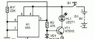
The diagram is shown in the figure. The circuit is based on a transistor two-stage low-frequency amplifier using transistors of different structures. The first amplifier stage is made on transistor VT1. The signal from the speaker, which acts as a microphone, is supplied to its base through the isolation capacitor C1. Capacitor C2 serves to suppress high-frequency interference that can be induced in a long cable running from the house to the gate in the fence, even if it is shielded. The DC operating mode of the first stage is set by the base resistor R1.
The connection with the second stage by direct current is direct; through resistor R3, a bias voltage is supplied to the base of transistor VT2, which also depends on the operating mode of the first stage (the operating mode of both stages is set simultaneously by resistor R1). But for alternating current the connection is through the separating capacitor C3. Without it, if done only through R3, the signal at R3 is attenuated as if it were a voltage divider and the amplifier operates with insufficient sensitivity.
If you remove R3 and connect the VT2 base directly to the VT1 collector, you also cannot set the operating mode with the highest gain. In general, this option turned out to be optimal. The VT2 collector is loaded onto the speaker. When the speaker is not connected, the amplifier does not work at all, since there is no current through the VT2 collector.
Power source - any DC source with a voltage of 9-12V, but with a well-filtered voltage. In this particular case, the power source was a power supply - a plug from the long-destroyed TV game "Dandy". According to the tag on it, it should produce a voltage of 9V at a current of 350 mA, in fact there is 12V at idle. Inside the power supply there is only a power transformer, a bridge rectifier and a 1000 µF capacitor. This power supply is quite sufficient for this circuit.
There are two speakers B1 and B2, one works as a microphone, the other for its intended purpose. One is on the fence (in the mailbox), the other is at home. Which one will work depends on the position of switch S1. Switch S1 is an old signal toggle switch with two switching groups. As you know, the signal toggle switch has a middle neutral position in which it is always located. In this neutral position it is not switched anywhere. And there are two extreme positions in which there is no locking, that is, the lever must be held in the switched state, and if released it will return to neutral.
In the diagram S1 is shown in the “listening” position. In this position, speaker B1, the one on the fence, is used as a microphone. A shielded cable runs from it into the house. It is connected through the upper contact group S1 to the input of the amplifier. And speaker B2, which is home, is connected to the collector VT2 through the lower contact group S1 in the diagram. And it works for its intended purpose - like a speaker. In this position S1 as in the diagram, you can listen to what the guest is saying, or eavesdrop on passers-by who stopped to talk at your gate.
In the opposite position, S1 will be in the “talk” position. In this position, the speakers switch roles. Now the home speaker B2 works as a microphone, and the signal from it through the lower contact group S1 in the diagram is fed to the input of the amplifier. And speaker B1, which is on the fence, is connected through the upper contact group S1 in the diagram to the collector VT2. Now the guest will hear what they say to him.
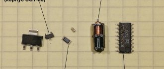
Few details. It is better to choose transistors with the highest transmission coefficient. The speakers seem to be Chinese, what brand or company is not clear, they are plastic, both diffusers and diffuser holders. Flat ring magnets. The magnets say: “F32QxO,25W”. Resistance 32 Ohm, power, apparently. 0.25W. It is quite possible that others with different resistance will do. But, given that these speakers also have to work as a microphone, the higher their resistance, the better.
After all, the greater the resistance, the more turns the winding has, and this means more EMF when working as a microphone. It is also desirable that at least B1 (the one on the fence) have a plastic diffuser, because in such conditions a paper diffuser will simply get wet from dampness and the speaker will deteriorate. S1 – signal toggle switch for two directions, with neutral. However, you can replace it with a P2K type button or a simple two-way toggle switch, but then you will also need to provide a power switch - first turn it on, then turn the switch to the desired position.
Because without a power switch, if S1 does not have a neutral, you will constantly listen to the street (and it can be heard quite loudly). Or anyone from the street will hear what’s going on in your home. The installation was extensive, I didn’t make a board, I just soldered the parts together. The circuit in the case hangs on contacts S1. To communicate with speaker B1 (which is on the fence), you need a shielded cable. The cheapest RK-75 for TV antennas is quite suitable. The setup consists of selecting the resistance of resistor R1 until the circuit begins to work as it should. You can temporarily solder a variable resistor instead of R1.
Rare intercom
I decided to start my writing on Habré with a very simple but useful project that has been living in my home for many years.
They once gave me an ancient phone. It was released, if not under Joseph Vissarionovich, then certainly under Nikita Sergeevich! Around that time Gagarin flew into space. In general, it's a cool thing! You can, of course, put it on a shelf “in a museum,” but somehow it’s not interesting. And the days of wired phones are long gone. It is necessary to provide the device with some functionality so that it can be used. I decided to make an intercom out of it. So:
First, let's study a typical diagram of a coordinate matrix intercom tube (I have exactly the same one and the diagram is very similar).
The pictures are clickable.
Remaking is not a problem. Just a couple of points:
So, let's disassemble the phone and throw out the extra giblets.
We need to leave: a dialer, a handset lever with contacts, pads for easy connection. Well, and a handset with a microphone and speaker, of course. The speaker and microphone need to be checked and a 4-wire wire connected to the handset. Clean and check the contacts of the dialer and handset lever.
We leave the board and speaker from the intercom handset. We use the speaker as a bell.
Now let's collect
We connect the handset to the corresponding contacts on the intercom board.
We attach the bell (the speaker from the intercom handset) to the phone body and connect it through the contacts of the handset lever (purple color in the diagram).
When the handset is put down, the contact is closed and the bell is included in the circuit. When the handset is picked up, the call is disconnected and the intercom takes over.
Let's connect a dialer as a door open button
He has at least 2 groups of contacts. Some count numbers (provide an interrupt during pulse dialing), but we don’t need them. We are looking for those that close when the disk is turned.
We dial any number on the disk, the contacts close, the door opens. Convenient though!
I soldered a jumper to switch SA1 just for reliability. Reed switch SA2 is not activated. We collect everything, check it, connect it. The intercom has polarity! Do you see the diode at the input? Don't confuse plus and minus!
Rejoice and enjoy the view
A telephone on a shelf fits into the design of the hallway much better than a poor white handset near the door. And the sound of the carbon microphone is awesome!
Guests are surprised and ask questions.
You can convert any rotary telephone using this method. So hurry up and search basements, closets and attics!
Source
Home telephone network of two phones
Hello, dear lovers of experiments and DIY experiments!
We have already touched on the topic of telephone communication on the pages of the DIY science and technology blog. Back then we were talking about a phone made from plastic cups. Unfortunately, such a telephone demonstrates very well some of the laws of acoustics, but in practice it can only be used in fairly ideal conditions - the telephone thread must be taut and must not touch any obstacles. Yes, and the length of the thread is limited. Another thing is a regular wired telephone. There is no doubt about its applicability. Despite the spread of mobile communications, it will not soon be forced out of apartments and offices. We’ll talk about it, and at the same time we’ll build our own simple telephone network, devoid of the above-mentioned disadvantages.
Did you know that telephone communication officially dates back to the 19th century, and since then the basic design of the telephone has remained virtually unchanged? This is true. Of course, the phone has changed in detail - a modern telephone includes electronic components that simply did not exist at the time of its invention. In telephone networks there are automatic telephone exchanges that switch subscribers among themselves. Various telephone services have appeared. However, the purpose of a telephone set of any circuit has remained unchanged since its invention by Alexander Bell in 1876 - converting sound into an electrical signal and transmitting it along a communication line to the desired subscriber and converting it back into an audio signal. And in this classic telephone connection there is no equal.
To demonstrate this point, let's compare the above-mentioned plastic cup phone to a regular telephone network. We have already talked about the disadvantages of the first - it is a short range, the absence of obstacles in the path of the communication line, and ensuring thread tension. In addition, let's estimate the speed of sound propagation in the first and second types of communication. Thus, the speed of propagation of a sound wave in iron is approximately 5000 meters per second. Even if we found a way to eliminate sound wave attenuation, sound from, say, Moscow to Vladivostok would take 30 minutes! I don’t know about you, but I would quickly get tired of such a phone - the radio signal reaches Mars faster! Another thing is the speed of propagation of an electrical impulse - 300,000 kilometers per second. There is no better intermediary for sound transmission. You just need to come up with a way to convert a sound wave into an electrical signal and vice versa. And this is exactly the method that Alexander Graham Bell found.
In his telephone set, the sound signal was converted into electrical impulses, which reached the opposite device through wires and were converted there back into a sound signal. Everything turned out to be as simple as it was ingenious! Of course, the first telephone network had no telephone exchanges, no dialers, or other modern telephone delights. There were only two telephone sets connected to each other by an electric wire. I suggest you check the possibility of the existence of such a telephone network. Moreover, it is quite possible to use such a telephone connection in practice, for example, to install telephones in a home workshop. And if you take such a phone to your child’s place of play, it will remain a key link in many games for a long time.
So, we will need:
As for the electrical wire - there is no need to limit yourself - any length of telephone wire can be used for your experimental or home needs. The type of wire can also be almost any. In my experiments I used 30 meters of twisted pair cable.
As for the DC source, we can say the following. In the telephone network, the voltage on the line at rest (when the phone is on-hook) is 60 volts. But for our experiments, the voltage from two Krona batteries will be sufficient. You can also use a 12-20 volt power supply.
Take the patch cord and cut it in half.
We clean the ends. The strands of the patch cord are often very thin, and it can be inconvenient to simply strip them with a knife. You can burn them.
If you use batteries, connect them in series. It is convenient to use clip-on contacts, but you can do without them.
We connect our current source to the circuit in series, that is, to the break of one of the wires.
Don't forget to insulate the contacts.
That's it, you can use it! The only significant drawback of this scheme is the inability to call a subscriber. To ensure this possibility, it is necessary either to supply alternating voltage to the line, as is done in city networks, or to install an additional line to provide sound or light calls.
(52) Comments
Yes, indeed, without the use of expensive telephone exchanges, you can organize a simple telephone network for personal needs. Oh, if in childhood I had known such a way to connect a friend’s phone, I would not have cherished, alas, the pipe dream of purchasing a toy, but quite functional set of two phones in the children’s world! Well, nothing, but now, as they say, I’ve come away