Why do you need illumination of the area near the computer?
There are several reasons to organize lighting for the PC user’s work area:
- Taking care of your eyes. Looking at a bright display in a dark room is harmful to the organs of vision, it causes overstrain.
- The need to take notes as you work, read books and magazines.
- Having snacks at the computer, drinking hot drinks. It is inconvenient to do this in the dark; you might knock over the cup.
Illumination inside the system unit with a transparent cover, in addition to solving practical problems, gives it an attractive, futuristic look. With its help it is easy to make your PC special.
Users' opinions on the backlight
On the Internet, the topic of computer backlights has gained remarkable popularity. This is due to the fact that it concerns almost every user. In general, people have completely different attitudes towards luminous elements. Some people think that backlighting is a waste of money, but the majority of people consider it an integral part of the computer.
Indeed, it is now more difficult to find a computer without backlighting than with it. It has become so integrated into everyday life that many people no longer pay attention to it. However, well-executed illumination will clearly make your computer stand out and make every game played on it special and memorable!
How does LED strip work and what are its properties?
The product is a flexible polymer-based board. There are 2 conductors attached to it and diodes connected between them, which emit light when current flows.
Advantages of the device:
- Economical. For 1 W of power consumption, the LED strip produces a luminous flux of 90-120 lm. For fluorescent and halogen lamps this figure is 25-50 and 15-20 lm, respectively.
- Durability. The lifespan of the diodes is 50 thousand hours if they are not subjected to overheating and voltage overloads.
- Simple and quick installation. The tape has an adhesive layer. Thanks to its flexibility, it can be mounted on a curved or broken surface.
- Low heat generation.
- Compactness. A small piece of tape is placed in the system unit.
If the computer is in the bedroom, the product can be fixed on the back of the monitor or under the table. Lighting with reflected rays will allow you to read texts, but will not disturb the sleep of other family members.
Popular devices are in the form of flexible PVC tubes with diodes inside. Their walls have a matte transparency, so the lamp looks like a neon lamp.
Diodes only allow current to pass in one direction. Accordingly, a constant voltage is applied to the tape.
Features of hand-made lighting
To avoid common mistakes when designing and installing backlight powered from a computer, here are some useful recommendations:
- As a rule, the total length of the LED strip is small, which can be explained by the small current output of a PC or laptop. Calculation of the length of the strip for RGB backlighting is carried out by simply summing the power of the LEDs included in it;
- the tape is attached to the target surface by gluing;
- to obtain a uniform light flux, it is advisable to use a so-called diffuser, which is usually an aluminum profile, one side of which is covered with matte plastic;
- A socket, like for a table lamp, is not required here - the LED strip is powered from the computer. But the connection methods can be different - directly to the MotherBoard, via a USB connector, or using a special connector with the required voltage;
- since the current consumption ratings of LEDs are small, the tape will not greatly increase the computer’s electricity consumption, but it is important to accurately calculate its permissible length;
- Since the RGB lighting is powered by the PC, it will come on when the computer is turned on and off when it is turned off. If a separate switching on of the backlight is required upon request, special switches are used.
Note that the factory tape usually has LEDs on one side and a layer of adhesive to facilitate installation on the other. The required length of the tape is obtained by simply cutting it.
Rules for connecting to the network
LED strips are designed for a potential difference of 12 V, models with the number of diodes 240 pcs./p. m - 24 V.
There are 2 ways to connect the light source.
Without power supply
To connect to a 220 V network, the parallel connection of the diodes is changed to a serial one. 220 is 18.33 times greater than 12, which means that it is necessary to connect 19 diodes or their parallel groups in series. Then the voltage drop across each of them will be 11.5 V.
The tape is cut according to special marks. If you cut it arbitrarily, the performance of the product will be impaired. The number of LEDs between the marks differs for different models, the minimum number is 3.
Thus, to connect to a 220 V network you will need at least 57 elements. When assembling the lighting device, polarity is observed: LED groups are connected by contacts of the same name.
To convert alternating voltage to direct voltage, a diode bridge is assembled. To smooth out ripples, a 300 V capacitor with a capacity of 5-10 mF is included in the circuit.
LED strips with fittings are available for sale, ready for use in a ~220 V network.
Via power supply
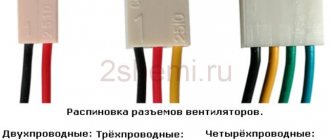
The lighting device must be connected to the output terminals of the converter, observing the polarity. They are guided by the color of the wire insulation: black or white – “minus”, others (mostly red) – “plus”. The switch and dimmer are installed in the gap of any wire.
The following power supplies are suitable:
- standard, made specifically for LED strip;
- from a laptop;
- computer (for backlighting in the system unit);
- phone charger.
The current consumed by the tape cannot exceed the rated value for this power supply. This value depends on the number of diodes and their type. The table will help you perform the calculation:
| LED type | LED density per 1 linear meter of strip | Current (A) per tape length | |||
| 1m | 2 m | 3m | 4 m | ||
| SMD3528 | 30 | 0.2 | 0.4 | 0.6 | 0.8 |
| 60 | 0.4 | 0.8 | 1.2 | 1.6 | |
| 120 | 0.8 | 1.6 | 2.4 | 3.2 | |
| SMD5050 | 30 | 0.6 | 1.2 | 1.8 | 2.4 |
| 60 | 1.2 | 2.4 | 3.6 | 4.8 | |
The wires are connected to the contact pads by soldering or using special connectors.
⇡#To summarize
To be honest, I don’t fully understand why in our country they are so categorical about everything related to lighting. Communicating with Western colleagues, I realized that, for example, in the USA, on the contrary, they pay a lot of attention to the appearance of PCs. Apparently, it is the Western audience, which, to be honest, is much, much larger than ours, that pushes manufacturers to create such products. Nowadays, only the laziest or conservative computer company does not produce devices with RGB elements. In any case, you, dear readers, always have a choice: if you don’t like the backlight, turn it off; I like the backlight - leave it, set it up, customize it, enjoy it. Having a choice is better than not having it. I repeat, there is no need to chase the backlight for the sake of the backlight. Our market is full of components with RGB elements, the quality of which has no serious complaints.
Previously, assembling a backlit system was considered a real adventure. Now we see that computer equipment manufacturers have made a huge leap forward. Working with RGB lighting synchronization technologies is very simple. This fact is clearly demonstrated by the example of MSI components. The user just has to make sure not to make a mistake with the PC components and connect them correctly.
Deepcool Quadstellar can easily be called one of the most unusual cases that visited our test laboratory. It's nice that 3DNews readers were the first to become acquainted with this model in Russia. It was very interesting to work with her. The device has an unusual appearance, but at the same time, assembling a powerful system with RGB lighting in it turned out to be convenient and simple. The Quadstellar design allows you to create a truly productive configuration - using multiple video cards, a huge number of drives and the ability to install custom water. I have no complaints about the manufacturing quality of the device. It is clear why many systems assembled in this case were presented at Computex. Perhaps the only drawback of the Deepcool Quadstellar is its high price, but when you look at the 14.5-kilogram array of aluminum and tempered glass, for some reason you cannot dare to say that such devices should cost much less.
We express our gratitude to the Russian representative offices of Deepcool and MSI, as well as the Regard computer store for their assistance in creating the material
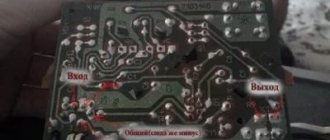
Connection diagram for a conventional LED strip
Electrical power is supplied through the computer's power supply's 4-pin Molex connector.
It includes wires:
- Black – “ground” (Gnd or COM).
- Yellow – voltage +12 V.
- Red – voltage +5 V.
They operate in this order:
- Cut off the connector.
- Strip the yellow wire and 1 black wire, the rest are insulated.
- The conductors and contact pads of the tape are connected by soldering. The yellow wire is connected to the “plus”, the black wire to the “minus”.
- Insulate the connection with heat shrink tubing.
In order not to cut off the connector, you can purchase a mating part for it (plug) as part of a Molex-SATA adapter. It is designed to power newer hard drives with a serial data bus. The SATA connector is cut off, and a tape is connected to the freed wires.
Next, the plug is inserted into the Molex connector. The maximum current for it is 20 A, but taking into account the presence of other devices (hard drive, DVD drive, etc.), it is not recommended to connect a load of more than 5 A (preferably up to 4 A).
You can implement a circuit with stepwise brightness adjustment. You will need a 2-position switch with a remote control function.
One of its contacts is connected to the “minus” of the tape, the other 2 are connected to the red (+5 V) and black wires of the connector. When the regulator is moved to the first position, a potential difference of 12-5 = 7 V is applied to the diodes, and they burn at half power.
You can connect a 24 V strip to a free power supply from a PC. The connector for power supply to the motherboard (MB-20 or MB-24) is used.
A voltage of -12 V is supplied to one of its contacts. A wire in blue insulation is suitable for it. In MB-20 it is located under the 12th number, in MB-24 – under the 14th. The “minus” of the tape is connected to this contact, the “plus” to the yellow wire (+12 V). As a result, the potential difference across the diodes will be 24 V. The maximum current when connected to the MB connector is 1 A.
To start the unit without connecting to the motherboard, install a jumper on the PS ON (green wire) and Gnd (black) contacts on the MB connector.
My impressions and conclusions
If you know how to solder and have all the necessary tools at hand, the difference between ready-made solutions and a self-assembled backlight system can reach up to a thousand rubles, but you can configure a self-assembled system exactly as you need, connecting in series as many segments as you like, as long as the motherboard connector has enough power and you can give free rein to your imagination.
If you don’t know how to solder and don’t have the necessary tool, then, I’ll be honest: if you want, modding is a good reason to learn something new. And for those who are not ready to bother, there is an excellent selection of ready-made solutions, for example, from DeepCool, the installation of which is extremely simple.
I am not an expert in PC modding and I launched this project as an experiment to try it myself and tell you what nuances may lie in wait for you in this difficult task. Therefore, immediately leave your questions if you have any. I will answer everything and the post will be updated.
Subscribe to our group on VKontakte so as not to miss new releases and be the first to know about upcoming activities and competitions!
RGB strip connection and diagram
The product consists of diodes of 3 colors - red, green and blue. There are 4 contacts: 1 “plus” and 3 “minus”. An RGB controller is required for connection. On one side it has 2 contacts for connecting to a constant power source. On the other hand, there is also 1 “plus” and 3 “minuses” for each color.
For installation in a computer case, a controller with remote control capability is required. There are programmable models that change colors automatically according to a user-specified scenario.
Main conclusions
PC backlight allows you to decorate your computer and reduce the negative impact of a bright screen on your eyes. The main task is to connect the power supply to the tape, for which there are several options:
During installation and connection, the main task will be to maintain the polarity of the connection and protect the tape from overheating. The user is not required to have deep knowledge of electronics, just basic school knowledge and some soldering iron skills. Please share your PC lighting options in the comments.
Source
Types of LED strips for connecting to a computer via USB
The USB connector has the following parameters:
- voltage – 5 V;
- rated current – 0.5 A.
The light source is connected through a converter that increases the voltage by 2.5 times. At the same time, the permissible current will decrease by the same factor - to 0.2 A.
Thus, 30 LEDs of the SMD 3528 type or 10 of the SMD 5050 type can be connected to the USB connector. The length of the strip depends on the density of the elements placed on it.
Backlit PC case on Arduino and WS2812 with CPU and GPU temperature display
I am glad to welcome everyone again to the “U Samodelkina” website. I like to play computer games sometimes. Sometimes these are calm turn-based strategies like Heroes or XCOM, and sometimes furious action like DOOM. And, of course, I want my computer to look beautiful and interesting. There are many ways to achieve this, but today I will focus on instructions for adding backlight to the system unit. Just adding LEDs or glowing coolers is too simple and uninteresting. We will cover the inside of the system unit with LED strip made from WS2812 and install an Arduino or Attiny85 or ESP8266 to control the strip. It will be possible to run a bunch of effects, which will diversify the look of the system. A garland from a system unit is certainly cool, but it’s also somehow too simple and boring. Therefore, there will be other uses besides beauty. We will use the backlight to display the CPU and GPU temperatures. We will run a program on the computer, which in turn will take readings from the computer’s sensors and send them to the controller that controls the WS2812 tape.
- Arduino (any version) or ESP8266 or Attiny 85 - ws2812 tape or rings - USB-TTL for Arduino Pro mini or ESP8266 - ISP programmer for Attiny (you can use any Arduino instead) - Connecting wires - Molex connector, female - Soldering iron, solder, rosin - Straight hands and accuracy
That is, in a body made of monolithic polycarbonate, plexiglass or the like. Or something similar
Connection diagram for backlight via USB
The connector has 4 pins. The second and third are used for data transmission, the first and fourth are for power supply. Dismountable plugs for the connector are sold in computer stores.
The LED strip is connected through a step-up voltage converter, which produces 12 V at the output. Such devices are also commercially available, but the circuit is easy to assemble with your own hands.
The converted voltage is constant, so it cannot be increased by a transformer. Instead, they use the LM2577 chip, which is a pulse width modulation (PWM) controller. Other radio components will also be required.
A USB plug is soldered to the input terminals of the converter, having first checked the polarity of the contacts in the connector with a tester. Connect poles of the same name. An LED strip is connected to the opposite side of the device.
Materials and tools required for work
Connecting LED backlighting is not fundamentally difficult and can easily be done with your own hands. To do this, you need to have some skills in working with a soldering iron and minimal knowledge. Tools you will need:
- LED strip for computer;
- 12V power supply;
- soldering iron and solder;
- scissors;
- connecting wires;
- nippers or side cutters.
The most necessary tools are listed, but other equipment may be needed.
How to make a backlight for a PC with your own hands?
They operate in the following order:
- Based on special marks, a fragment of a given length is cut from the tape,
- Treat the contact pads (lamellas) on it with alcohol.
- Using a puller or a utility knife, remove the ends of the wires from the insulation to a length of 5 mm.
- The exposed area is twisted into a tourniquet.
- Dip the stripped ends of the wires into rosin.
- Flux is applied to the contact pads of the LED strip using a toothpick.
- Take a small dose of solder with a heated soldering iron tip and transfer it to the lamella. To avoid burning it out, the contact time should be limited to 1 second.
- Solder tubercles are formed similarly on other contact pads of the connected tape.
- Brown deposits from the flux are removed with a napkin. If it has time to harden, this will require alcohol.
- Use wire cutters to shorten the bare ends of the wires so that they are equal in length to the lamellas. Otherwise, a short circuit may occur when the wires are bent.
- The core is placed on a tubercle of solder and pressed into it with a heated soldering iron. Contact duration is limited to 1 second.
- Before the solder hardens, ensure that the connection remains motionless. This takes a few seconds.
- Having soldered all the wires, clean the contact points from flux with a cloth soaked in alcohol.
- Place a heat shrink tube over the assembly and heat it.
- Cut off the SATA connector from the adapter.
- Strip the ends of the yellow and one black wires. The rest are trimmed and isolated.
- Heat shrink tubes are put on.
- Twist the wires from the LED strip and the connector in compliance with the polarity. Then the connection is soldered.
- Slide heat-shrinkable tubes over the contact points and heat them with a hair dryer, match or gas lighter.
- Insert the adapter plug into the Molex connector.
The RGB strip is connected in the same way. To avoid confusion, it is recommended to solder wires in insulation of different colors to the “cons”. Next, connect the cores from the Molex-SATA adapter to the RGB controller. On the other hand, wires from the LED module are connected to it.
The backlight assembled in this way lights up simultaneously with the computer startup. To be able to extinguish it during the day, a microswitch with a remote control function, for example, from a smartphone, is soldered into the gap of one of the wires.
The installation process is simplified if you purchase a piece of tape with wires already connected.
Marketing highlighting
It is probably obvious that glowing computers and various electronic accessories, for example, a backlit computer cooler or gaming mice with neon inserts, are in greatest demand among similar components.
Many companies that produce such attributes greatly inflate their prices, precisely explaining this by the fact that their lighting is the best.
In fact, it is almost impossible to predict demand in this case, because it mainly depends on the buyer what kind of lighting he will choose. But here's what to remember:
- You should not choose the luminous attributes of a computer, focusing only on the illumination part. You need to understand that the main thing is the characteristics. Even if the backlight is not ideal, it can be easily modified and refined later, but it will be more difficult to cope with the characteristics on your own.
- You don't have to believe everything they write! A fairly common marketing ploy is to write or draw on the packaging something that the product cannot actually do. You should be very careful when choosing, and if possible, even check the product directly in the store.
Add a link to a discussion of the article on the forum
RadioKot >Laboratory >Amateur Radio Technologies >
| Article tags: | Add a tag |
LED backlight for computer desk
Author: DooMmen Published 09/15/2012 Created with the help of KotoEd. Participant of the Competition “Congratulate the Cat as a Human Being 2012!”
Once we decided to renovate the room and update the furniture, but due to lack of space and interior features, a fairly small computer desk was ordered and made, on which a laser printer, a monitor fit, and my boxes and bags with various parts were placed.
Everything was fine, but the first inconvenience when using the computer is that in the dark you can’t see the inscriptions on the keyboard, which is located on a pull-out shelf. The solution was simple - white SMD 1206 LEDs mounted on small scarves and connected in parallel were glued above the keyboard under the table cover. The power was taken from USB and a small control and stabilization board was assembled on LM317 and K561TM2, but this was a temporary solution, since the power depended on the computer.
The second problem was the lack of any lamp on the table, and especially the lack of space for it. On the left side of the table above the printer there were two small shelves on which there was a digital thermometer and various little things. I considered installing a lamp with a shelf mount rather unaesthetic and decided to approach this issue from a technical point of view, namely, to make an LED backlight, especially when I found out that we sell 3W LEDs on a substrate, and collimators for them (the collimator was ideal for me at 25 ° in a cylindrical body, although it was necessary to drill holes at the base of the collimator for the screw heads and make slots for the wires).
To begin with, a small 3W light module was assembled on a flat radiator (I don’t remember exactly, but perhaps from the motherboard, judging by the ears):
Next, the driver was assembled using an almost standard step-down circuit on the ZXSC400:
This driver circuit has long been widespread on the Internet, and differs from the standard one only in improved current stabilization.
The module is almost assembled for testing:
Next, the location of the module on the table and the mounting method were chosen experimentally - it settled on the left edge of the second shelf, attached to a bent sheet of iron pressed to the table with a large clothespin, which at the same time served as a support for the wire: This unit is connected with a two-core wire (power and PWM) to the main control unit: The control unit in the photo differs from the circuit in the presence of a linear stabilizer for parallel-connected keyboard backlight LEDs, although under the monitor it’s the same story, but for the monitor backlight I assembled a separate switching stabilizer board, since with such a power supply it is necessary to dissipate more power , and the system efficiency is very low.
This control unit is located under the table cover above the keyboard shelf on the left. The board itself is glued with double-sided tape, the buttons and LEDs are mounted on an aluminum corner with a fiberglass overlay to match the color of the table.
The control unit circuit and firmware have been modified for the use of 12V LED strips, or homemade assemblies of 12V LEDs connected in series:
The basis of the block is ATtiny2313. Unlike the version in the photo, the key transistors have been changed to more modern ones. Then the epic began with the search for a normal switching power supply (SMPS). Initially, attempts were made to use SMPS from 60W halogen lamps, but after trying to get this source to start at such a low load and several explosions, I realized that I had to make the source from scratch (fortunately, the housing remained). Then an article from the magazine Radio No. 3, 2009, caught my eye. “Advanced SMPS in a matchbox” and I decided that this was what I needed.
After manufacturing this SMPS and winding the transformer, tests of this source began (I somehow didn’t want to connect a circuit with an expensive LED). In the circuit, at rated load, the transformer got hot and made noise, the powerful resistor dampening the emissions of the primary transformer overheated, the Schottky diode overheated and was desoldered from the board. Since the SMPS was assembled using a Power Integration TNY255 microcircuit, the microcircuit was replaced with a more powerful TNY265, the PI Expert Design Software program was downloaded from the manufacturer’s website, and the circuit was redone (a copressor was installed instead of a resistor, the Schottky diode was changed to a fast SF35, the turns of the transformer were recalculated , although the numbers were lost).
Since this article is not about the manufacture of a power supply (there are already more than enough circuits for which), and since the data necessary for the manufacture of such a power supply was lost, and even photographs were not left, but it stands glued to the back wall of the table behind the table itself and It has been working 24/7 for more than 2 years, I won’t talk about its production, and even now a ready-made power supply is sometimes easier to buy than to make.
After installing the system, I decided to make a small program for the computer and connect it all via RS-232 to the computer. The program was written in VB for Windows, it runs in the tray, and when you click on the icon, it appears in the form of a small window with buttons and a regulator.
To connect to the computer, a MAX232 board was assembled, which was connected with a connector to the main board and was glued next to it with the same double-sided tape. Power for this board was taken through diodes from pins 4, 7 of the COM port, and a stabilizer on the 78L05, assembled in the connector housing, although it was possible to power it from the board itself, although I did not foresee this.
To be honest, the mechanical controls on the table turned out to be more convenient than the program, and after changing the OS to Ubuntu, I did not port the program and cut the wire, so I will not give a screenshot of the program, and the program itself with the source code is in the archive.
Now briefly about the functionality of the block:
- 2 channels of backlight control based on LED strip (under the monitor and above the keyboard);
- Control of 3W LED module using PWM;
- Smooth on/off of all lights;
- Smoothly adjustable 3W LED brightness with level memory;
- Possibility of connecting to a computer.
Now briefly about the buttons:
- Buttons LA, LB turn on/off the corresponding LED backlight;
- The Up, Down buttons are designed to control a powerful LED, namely:
When the light is off, briefly pressing the Up button turns on the backlight;
- When the light is on, briefly pressing the Down button turns off the backlight;
- When the light is on, long pressing one of the UP/Down buttons decreases/increases the brightness of the LED; after releasing the buttons, there is a short pause during which you can continue adjusting.
Indication:
- The green LED indicates pressing the button, as well as the process of adjusting the brightness (and also indicates the passage of a data packet from the computer);
- The red LED lights up during brightness adjustment, and turns off when the brightness value is saved.
Microcontroller fuses: all by default, internal RC oscillator at 8.0MHz with minimum start time (Low = 0xC4, High = 0xDF). Result:
Details: in the driver, instead of a current sensor resistor (0.033 Ohm), 3 parallel-connected resistors 1206 of 0.1 Ohm each are used, a 22 µH inductor for 1.9A, any powerful LED for voltage up to 8V and a current of 0.7A, a 78L05 stabilizer is used in the control system circuit SO-8 case, key transistors are any N-channel suitable for current.
You can use any suitable power source, taking into account the supply voltage of the backlights (12V when using an industrial LED strip), the power of the power source depends on the consumption of the backlights, and in my case it was 15W (with a margin).
Files:
Circuits, boards, program, sources, firmware.
All questions in the Forum.
| What do you think of this article? | Did this device work for you? | |
| 10 | 1 | 0 |
| 0 | 0 |
Why do you need illumination of the computer area?
The computer is becoming an increasingly necessary tool for business, communication and leisure. People spend a lot of time in front of the monitor screen, which negatively affects their vision.
The most harmful effects occur when working in a dark room. The sudden transition from a brightly lit screen to a dark background tires the eyes and can cause headaches with prolonged exposure. You can reduce the harmful effects by installing additional lighting in the monitor area.
The best option for a soft transition is to install an LED strip around the perimeter of the back side of the monitor. The light is directed towards the wall, creating an illuminated spot around the screen. This option allows you to smooth out the sharp boundary between light and darkness, does not distract the eye from the main object of attention and reduces the harmful effects of prolonged contemplation of the screen.
Preparation
First of all, you need to purchase everything you need for work. It is worth remembering that the LED strip can be ordered from China, but in this case there will be no guarantee as such. If you buy it in a store, you will have to overpay, but if problems arise, you can return the product under warranty. You need the following:
- LED Strip Light. Choose a single-color or multi-color option depending on the purpose. Only products designed for 12 V voltage are suitable.
- Sharp knife. The easiest way is to use a stationery or construction one with replaceable blades. Scissors may also be needed.
- Side cutters, you can use wire cutters instead.
- Wires for connecting elements.
- Soldering iron, as well as solder and flux. You should select small options with a small tip; it is impossible to solder contacts with a standard device.
- Connectors, with their help it is not difficult to connect wires without soldering. Select according to the type of tape. For example, RGB has 4 pins, RGBW has 5, and RGBWW has 6.
Connectors for connecting LED strip.
For a multi-color option, you need to install a controller, with its help you can change the backlight shades. If you connect directly, either only one color will light up, or all of them at once.
To adjust not only the color, but also the brightness, you need to additionally purchase a dimmer.