You don’t really need to look for it, it just catches your eye. TDA microcircuit with a protruding “comb” - a cooling radiator and a corresponding “piping” of electronic components. Before cutting out the required fragment of PCB with parts using a hacksaw, it is imperative to obtain a schematic diagram.
Antenna amplifier: master class on how to make and use a simple device with your own hands
Today, over-the-air television broadcasting is still the most common form of receiving information. But a high-quality signal is provided only by the coverage area of the tower, and if you are outside it, then you need to take care of the quality yourself.
The solution to the problem in such a situation will be an antenna amplifier. However, it is not necessary to buy it, since it is quite possible to make it yourself from scrap materials.
Why do you need an antenna amplifier? Features of the concept
An antenna amplifier for a car radio and TV is connected to the antenna if they want to improve the quality of audio or TV signal reception.
It is used in the following situations:
- long distance from the repeater to the receiver;
- wrong choice of antenna.
Thanks to this device, you can significantly improve the level of the displayed image. The optimal place to install a do-it-yourself antenna amplifier is considered to be a place close to the receiver. This is explained by the fact that the signal tends to decrease as it travels along the cable.
But in some situations, for example, in the case of remote reception, it makes no sense to install a signal-amplifying device close to the receiver.
Device types
As you can see in the photo of antenna amplifiers, they are:
Broadband. This type of device is used if it is necessary to improve image reception on several receivers simultaneously. They are usually installed in multi-storey buildings. A broadband device can operate not only in the DMB, but also in the MV range.
Range. With their help, it is possible to receive television signals from remote television towers. A range amplifier enhances the signal level and eliminates interference.
Multi-band. Such devices will be used to provide improved images from receivers located on high masts. The use of multi-band type devices is possible in the case of small collective reception systems.
Making a signal amplifier with your own hands
Consider the circuit of a simple antenna amplifier. Its entanglement begins from a power source with a voltage of 2.8-5.2 V. A device using this circuit is characterized by almost silent operation (the noise produced is only 2 dB) and has a fairly high gain (approximately 13 dB).
Another plus is that the assembled circuit does not need to be configured. The above device is suitable for indoor TV and radio antennas.
Work order:
- Prepare all the required electronic stuffing.
- Organize your tools and supplies.
- Make a printed circuit board. Moreover, it is better not to use a hinged assembly and special mounting panels, otherwise the device will produce too much noise during operation.
- Solder all electronic components.
- Check the resulting device carefully.
- Connect it to the antenna and receiver.
As for the power source, a more detailed description of how to make a power supply for an antenna amplifier can be easily found on the Internet.
Features of connecting a signal amplifier to a TV
The most important thing here is that the device is located as close as possible to the TV, because cable losses have a significant impact on the image level. This requirement applies not only to personally assembled devices, but also to purchased ones. An exception can be made only for antennas with a short cable.
Do not forget to carefully read the instructions for checking and connecting the amplifier. This will help avoid many problems.
If you have connected a signal-amplifying device, but no positive changes have occurred in the picture level, then you should check the direction of the antenna and the wave correspondence of these devices to each other.
Remember that all actions must be performed with the equipment turned off from the network.
Do not connect the amplifier to an external antenna that is not equipped with lightning protection.
In conclusion, we note that when creating an antenna amplifier, one must strive not only to amplify the signal, but also to ensure that the device produces as little noise as possible. To achieve this, use high quality parts and stay at the minimum dimensions for the device.
Photos of antenna amplifiers
Antenna amplifier: features, pros and cons
Our country is completely switching to digital television, abandoning the outdated analog signal. This means that now almost every home has a special antenna connected to it, which transmits the relevant information to the TV receiver. But what to do if your home is located at a considerable distance from a television tower and you often have to deal with interference?
Professionals will advise you to purchase an antenna amplifier. To do this, you will have to go to a specialized store and pay a considerable amount. But there is another solution: make the amplifier yourself. To accomplish this, you do not need special skills or a large amount of additional materials. You will learn about what needs to be done in this article.
Features of the antenna amplifier
The purpose of the amplifier is to make the antenna “active”. Let's take a closer look at this concept.
There are two types of television antennas:
They differ from each other in that passive devices receive a signal solely due to their shape, while active versions also contain other active elements. By adding an amplifier to the antenna, you will make it active, which will significantly improve the signal and achieve high-quality image and sound on the TV receiver.
Strengthening a television signal without turning on additional equipment
As it turns out, you can amplify the signal of a television antenna using a regular piece of coaxial cable. We are not talking about excluding the receiver from the circuit if the TV is an old model. It’s just that many homes have common antennas installed, and they may not work well. In this case, you can resort to one trick.
PHOTO: idistribute.ru Coaxial cable with soft insulation - you need to order exactly this
What is needed to make an amplified TV antenna?
Everything here is extremely simple. All you need is a regular antenna plug, a small piece of coaxial cable, a knife and pliers. The length of the coaxial cable section will depend on the frequency, which is different for each region. But we’ll look at step-by-step instructions to find out how to find out.
Making an antenna that does not require an amplifier: step-by-step instructions
Let’s immediately say that if the distance to the transmitter (tower) is more than 15 km or there are many obstacles on the way, you will still have to use a signal amplifier for the TV antenna. But if such problems are not observed, then the antenna can be made within 5-10 minutes.
If you are interested in a complete master class on making such a homemade product, you can watch it in this video.
Thus, we can say that even without an amplifier you can make an antenna for a TV with your own hands - it will work just as well.
DIY antenna amplifier - simple signal amplifier circuits
Although television is constantly evolving, expanding the network and increasing the capabilities of television equipment are not a guarantee of high picture quality. The specificity of the TV signal limits the distance over which it can be transmitted. In mountainous areas and in areas far from the tower, carrier waves arrive greatly weakened, which makes it impossible to receive individual channels.
In addition, incorrect design and shape of the antenna, errors in its installation, distance from the receiving and transmitting radio equipment - all this also negatively affects the picture level.
The solution to this problem is to create an antenna amplifier for digital television with your own hands.
Features and circuit of the antenna amplifier
An amplifier is a device designed to amplify a poor, unstable TV antenna signal. The advantages of this device are as follows:
- amplification of a television signal in a fairly wide frequency band;
- the ability to receive even a very weak TV signal;
- quiet operation.
The disadvantages include:
- the risk that the device will self-excite;
- High power signals in the meter wave range may overload the device;
- susceptibility to the effects of lightning currents;
- passive output losses.
The DIY antenna amplifier diagrams indicate how the device should be connected to the TV. The TV cable goes to a device that amplifies the signal, and then the signal goes to the TV. This scheme is universal.
Antenna amplifier for UHF
Modern digital television is broadcasting on decimeter waves (UHF). Frequency range – from 470 to 1270 MHz. The simplest solution for long- and ultra-long-range TV signal reception in the UHF range is to use a structurally simple antenna with an amplifier located close to it, which one can easily make with one’s own hands.
A DIY UHF antenna amplifier must have a significant gain, create a minimum of noise during operation and be resistant to temperature changes
A simple design, availability of the raw materials necessary for its creation and the absence of a tendency to self-excitation are other important requirements for such a device.
Antenna amplifier for FM receiver
To make an fm antenna amplifier at home, you will need:
- large round aluminum plate;
- a piece of copper wire;
- tractor rubber belt;
- TV cable;
- metal bracket (preferably aluminum);
- adapter;
- self-tapping screws – 4 pcs., nuts – 2 pcs., bolts – 2 pcs., washers – 2 pcs.
How to make a sound amplifier from a TV
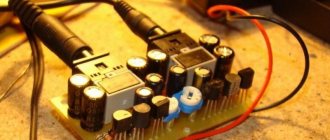
After disassembling old domestic televisions of the USCT series, there are many blocks of boards, including control units. In addition to the controls, the control units of TVs 3USTST, 4USTST also contain low-frequency amplifier module boards.
The most popular control units were BU3 (Fig. 1), as well as BU411 (Fig. 2) and BU413 (Fig. 3). Each of these blocks contains an A9 board (A9.1), on which the ULF circuit is mounted. as well as some nodes that are not related to ULF. The low frequency amplifier of the BU3 control unit is based on the K174UN7 microcircuit.
This is a fairly old chip with mediocre characteristics. But. nevertheless. The ULF of the BU3 block has an output power of 3 W. at THD 10% (1 W at THD 1.5%) and operating frequency range 6,015,000 Hz with unevenness 6 dB.
In the OOS circuit of the sound amplifier, a tone control operates for low and high frequencies, providing fairly high control efficiency (compared to passive regulators).
Volume control is not provided because volume control on these TVs is carried out electronically in the radio channel module. Therefore, when constructing an independent ULF based on these boards, you will need to make a regular passive volume control using variable resistors. The nominal supply voltage of ULF BU3 is 15V.
But the bass amplifier works normally in the range from 10 to 16.5V. The X4 connectors are directly installed on the ULF A9.2 board. X16 and X8 The remaining connectors are located outside the board and are connected to it with ribbon cables. The connection points for these cables are indicated by numbers in the diagram. The common minus points are points 27. 24. 21, 16. The supply voltage is supplied to point 14.
And the input signal is at points 20 and 19.
TV sound amplifier
Figures 2 and 3 show diagrams of control units BU411 and BU413. which were used in 4USTST TVs. According to the ULF circuits, these blocks are completely identical. The only difference is in the control circuits. In the first case, the control is push-button, in the second it is analogue, with variable resistors. But this has nothing to do with ULF.
A9 boards contain ULF based on the K174UN14 microcircuit, which is more modern than the K174UN7 block BU3. and has significantly better sound quality. But the tone control for low and high frequencies is made according to a passive scheme, which somewhat worsens the depth of its adjustment.
The ULF block BU 411 and BU413 has an output power of 6 W, with a THD of 10% (4 W with a THD of 0.15%) and an operating frequency range of 4,016,000 Hz with an unevenness of 6 dB.
This ULF in the TV circuit is powered by a voltage of 15V. but it is operational in a much wider range of supply voltage from 8 to 18V. In this case, only its maximum output power changes, which at a load with a resistance of 2 Ohms can reach 10 W (at a THD of 10%). The sensitivity of the K174UN14 microcircuit is about 50 mV. which allows the use of a passive tone control. included at the entrance. Volume control is also not provided. Therefore, when designing an ULF based on these boards, you will need to make a regular passive volume control using variable resistors.
Power amplifier on the K174UN14 chip (TDA2003)
On the low-frequency amplifier A9 board of the BU411 or BU 413 unit, connectors X1 and XS1 are directly installed. The remaining connectors are located outside the board and are connected to it with ribbon cables. The connection points for these cables are indicated by numbers in the diagram. The common minus points are points 2. 4, 1, 7. The supply voltage is supplied to point 5. And the input signal is supplied to point 6. Figure 4 shows the circuit of a stereo amplifier based on the A9.2 boards of the BU3 control units.
The input signal comes through connector XI. The resistance values of resistors R1 and R4 depend on the output of the signal source. If it is a linear output, for example. DVD player. then they can be the resistance indicated on the diagram or they can be removed altogether. If the signal is supplied from a telephone output, for example, a pocket MP3 player, then the resistance of these resistors must be reduced to values that ensure normal load of the telephone amplifier (usually 50-100 Ohms is enough).
Resistors R3 and R6 are separate volume controls. The tone controls are not shown in the diagram because they are included in the boards. Circuits R2 C2 and R5 C4 serve to suppress interference with a sampling frequency that may be at the output of a digital signal source. Figure 5 shows a stereo amplifier circuit based on A9 boards of the BU411 or BUZI control units. The power source must produce a constant voltage within the limits indicated in the diagrams, with a maximum current of up to ZA in the diagram in Fig. 3 and up to 5A in the circuit in Fig. 4. It should be noted that the use of different types of ULF boards in the same stereo amplifier is not permissible.
Source: https://www.radiochipi.ru/usilitel-zvuka-iz-televizora/
| When I was disassembling an old color TV with a remote control (I don’t remember the brand) and noticed an amplifier on a separate board, after removing it I found out that it was on a k174un14 chip. I immediately decided to check the functionality - I found the power supply terminals, the signal input, connected it - it turned out to be working. In addition, there was also a simple equalizer for high and low frequencies. I decided to build a type of subwoofer based on it, and I immediately found a speaker from a burned-out music center. One speaker was burnt out, and the second was working. For the amplifier case, an old first aid kit came handy - I drew a hole for the speaker, melted it with a soldering iron (smoked the whole house) and made more holes for the equalizer controls. First I installed the amplifier, securing it to one bolt - I don’t think it will fall off, then I secured the speaker to 4 bolts, having connected everything, the question arose of how to close the back cover. At first I thought about making it with a soldering iron, but then I decided to use glue for the moment. After gluing it, I waited until it dried, connected it to the laptop - and the bass shook the whole table, perfect for gaming! If you liked the diagram - like it! SCHEMATIC DIAGRAMS OF ULF See more amplifier circuits VALUES AMPLIFIERS TRANSISTOR AMPLIFIERS AMPLIFIERS ON CHIPS ARTICLES ABOUT AMPLIFIERS | An excellent, and most importantly, easy to assemble, UMZCH for a home audio system, can be soldered based on the LM3875 operational amplifier. The link contains a datasheet. This is a large heatsink-mounted chip, much like the famous 7294, and can produce 60W RMS of continuous power, and even 100W in peaks. Dependence of power on supply voltage LM3875
The case is quite small and looks very elegant with an external power supply. Amplifier based on LM3875 - assembly diagramLook at the diagram - how few parts this amplifier has, it cannot be compared with the TDA7293. The block size is only 120 X 100 X 30 mm. The case has two volume controls, gold-plated iron terminals, gold-plated input jacks, 5600uF filter capacitors and thick copper speaker wires. All wiring inside is wall-mounted, ferrite rings at the end of the 220V power cord are used to reduce any interference penetration into the amplifier. External ULF power supplyPower is supplied to the UMZCH through an external power supply. The power of the power toroidal transformer is 160VA. After the bridge rectifier, +/-35V is obtained. Two 4.7uF polyester capacitors are used to pre-filter the power supply. Sound checkThere is a good, strong and clear sound. The amplifier is used as a multimedia amplifier, loading a 12″ speaker at the base of a 3-way system. The circuit drives these speakers easily and loudly when required. If you liked the diagram - like it! SCHEMATIC DIAGRAMS OF ULF See more amplifier circuits VALUES AMPLIFIERS TRANSISTOR AMPLIFIERS AMPLIFIERS ON CHIPS ARTICLES ABOUT AMPLIFIERS | This amplifier is very easy to make, and it is also very compact, working with only one low voltage power supply, the value of which can be between 4 and 12 volts. The circuit is based on the use of a microcircuit like LM386 - an operational amplifier capable of delivering several hundred milliwatts of power alone into an 8 ohm load, while consuming only a few mA at rest.Chip parametersThe circuit is ideal for small portable battery-powered UMZCHs. |
Advantages and disadvantages
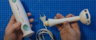
The pros and cons of the resulting device depend on the method by which the old radio was turned into a sound amplifier.
The advantage of a homemade device is savings. You don't have to buy a special device to help improve the sound. In addition, this option allows you to extend the service life of equipment that for some reason has become unusable or has been partially broken.
The sound obtained with such a device is also an advantage: its quality will be as good as that purchased in a store. If used correctly, the service life can be several years. In addition, in some cases, the gadget will not require a connection to a cigarette lighter socket to operate.
Some options can read various media containing music files.
Self-made devices also have disadvantages. The design has a less reliable layout than devices from the store. A cable that often sticks out during self-assembly is also inconvenient. If a person has assembled an amplifier from a car radio unprofessionally, extraneous noises, crackling noises, and sounds during operation may appear. Sometimes such unpleasant effects appear only when the volume is greatly increased.
Article on the topic: How to weld a TV on a VAZ 2114
It should also be remembered that the maximum voltage possible in the on-board network of the machine is not always sufficient to obtain the maximum power of the low-frequency audio amplifier. This difficulty is eliminated by connecting capacitors with a large capacity.
Often tape recorders are installed in cars during assembly, the quality of which is not very high. For this reason, the sound may not be of very good quality if you increase the volume. The sound, however, in this situation will be bad even without connecting a homemade amplifier.