Club "Krylatskoe", school "Intellectual": Vasily Kuznetsov, Vasily Kvitko
Head - Alexander Vladimirovich Efimov
In development of work on Stirling engines, we turned to one interesting engine. Presumably at the beginning of the 20th - end of the 19th century it was called the “Lehmann engine”. Nowadays it is usually referred to by the phrase Simple Lamina Flow.
Its design is quite simple. Typically this is a glass flask, approximately half filled with porous metal material, which is heated by an alcohol lamp at the border of the filler. There are areas unfilled with filler on the blind and open parts of the flask. On the open side there is a piston with a connecting rod and a flywheel (experiments indicate that a free piston and a U-shaped glass tube with a “liquid piston” can be used). The main condition is that the piston must be well ground and have minimal friction against the walls.
The engine, unlike the classic Stirling, must be “started”. To do this, you need to either spin the flywheel, or, if this is an option with a free piston, push the latter inside the flask. Perhaps not the first time, but the engine starts even with dimensions of 25x156 mm and runs at a frequency of 6.7 Hz.
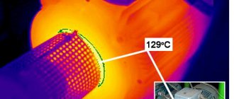
When describing the operation of the engine, the authors, as a rule, refer to the thermoacoustic effect, which can be observed on the so-called “Rijke tube” (you can read about it in the book by B.V. Rauschenbach “Vibration Combustion”, Moscow, 1961). The Rijke tube is a cylinder, the main axis of which is oriented vertically, with a mesh inside. The mesh is placed at a distance of approximately a quarter of the height of the cylinder, counting from the base. If the grid is heated strongly enough, a strong sound appears at a frequency corresponding to the second harmonic. The frequency of the first harmonic can be determined using the formula f = a/4l, where a is the speed of sound in the gas inside the tube, l is the length of the tube. A prerequisite is the presence of strong traction (the term “through traction” is usually used). The temperature measured at the tube outlet rose to 100 °C, and the frequency of the emitted sound for a 1 m long tube was approximately 180 Hz, which corresponds to the second harmonic. The sound was so strong that with a tube diameter of about 70 mm, window panes began to tremble. With some skill you can extract sound from almost any tube. A tube of smaller diameter (0.02...0.018 m) and shorter length (0.5 m) produces sound at a frequency of about 333 Hz, which also corresponds to the second harmonic. The speed of air movement, measured by the cinegram, was 1.2 m/s (in the area preceding the appearance of sound - 0.4...0.7 m/s). Theoretically, for the occurrence of acoustic vibrations, an air velocity of at least 0.6...0.7 m/s and a tube extension of at least 14 gauges are required. In our experiments, it was possible to extract sound from tubes with relative lengths from 11 to 27 calibers.
The reason for the sound in the “Rijke tube” is as follows. The hot mesh heats the air and it, having a lower density, rushes upward; in this case, a certain speed of air movement is established in the mesh area. An air “plug” of lighter air reaches the end of the tube, and as a result, a sound wave (disturbance) begins to move downstream. Having reached the grid, the wave (an area of high pressure) causes a local increase in density and, as a result, a decrease in flow velocity. A decrease in flow speed leads to an increase in the time the air remains near the mesh and the appearance of a new “warm bubble” of air, which again moves upward. If the grid is at the antinode of a standing sound wave, then self-sustaining self-oscillations arise.
If the tube is located horizontally, then for sound vibrations to occur, air must be pumped through the tube at the previously indicated speed. In this case, a mechanism is realized due to the presence of “thermal resistance”. In the area of heat supply, there is a local decrease in air density and a local increase in speed. This leads to an increase in pressure in front of the heater, since the air flow remains unchanged. In turn, an increase in pressure causes an increase in the speed of air movement in the heater area. The heater temperature decreases, and the thermal resistance also decreases. The speed of air movement begins to decrease, and the temperature of the heater begins to increase, as a result of which the cycle repeats.
In operating models of thermoacoustic engines, the heater is also located at a distance of one third to one fourth of the total length of the tube, on the side of the open end. However, the measured frequency of piston movement is significantly, in our case 30...50 times, less than the sound frequency of the “Rijke tube”. Consequently, if acoustic phenomena are present in this engine, they are of a different nature. However, the analogy with a horizontal tube seems fair to us.
Story
The Stirling engine is a heat engine that was invented in the early nineteenth century. The author, as is clear, was a certain Stirling named Robert, a priest from Scotland. The device is an external combustion engine, where the body moves in a closed container, constantly changing its temperature.
Due to the spread of another type of motor, it was almost forgotten. Nevertheless, thanks to its advantages, today the Stirling engine (many amateurs build it at home with their own hands) is making a comeback again.
The main difference from an internal combustion engine is that the heat energy comes from outside, and is not generated in the engine itself, as in an internal combustion engine.
Thermoelectric Peltier converter
A Peltier element (EP) is a thermoelectric converter that operates using the Peltier effect of the same name, one of the three thermoelectric effects (Seebeck and Thomson).
The Frenchman Jean-Charles Peltier connected wires of copper and bismuth to each other and connected them to a battery, thus creating a pair of compounds of two dissimilar metals. When the battery was turned on, one of the junctions would heat up and the other would cool down.
Devices based on the Peltier effect are extremely reliable because they have no moving parts, require no maintenance, do not emit harmful gases, are compact and have the ability to operate bidirectionally (heating and cooling) depending on the direction of the current.
Unfortunately, they are ineffective, have low efficiency, and emit quite a lot of heat, which requires additional ventilation and increases the cost of the device. Such devices consume quite a lot of electricity and can cause overheating or condensation. Peltier elements with dimensions larger than 60 mm x 60 mm are practically never found.
Tags: , machine, anode, antenna, beat, sconce, windmill, view, harm, alignment, generator, engine, house, , capacity, grounding, replacement, how, design, circuit, , , power, voltage, alternating, constant, potential, rule, principle, wire, start, , work, size, relay, repair, row, garden, light, network, system, term, stabilizer, circuit, ten, type, current, installation, shield, electricity, effect
Principle of operation
You can imagine a closed air volume enclosed in a housing with a membrane, that is, a piston. When the housing heats up, the air expands and does work, thus bending the piston. Then cooling occurs and it bends again. This is the cycle of operation of the mechanism.
It is no wonder that many people make their own thermoacoustic Stirling engine at home. This requires the bare minimum of tools and materials, which can be found in everyone’s home. Let's look at two different ways to easily create one.
Do-it-yourself thermoelectric generator device
Such complex processes that take place in TEG do not stop the local “Kulibins” in their desire to join the global scientific and technical process of creating TEG. The use of homemade TEGs has been around for a long time. During the Great Patriotic War, partisans made a universal thermoelectric generator. It generated electric current to charge the radio.
With the advent of Peltier elements on the market at prices affordable for household consumers, it is possible to make a TEG yourself by following the following steps.
- Purchase two radiators from an IT store and apply thermal paste. The latter will facilitate the connection of the Peltier element.
- Separate radiators with any heat insulator.
- Make a hole in the insulator to accommodate the Peltier element and wires.
- Assemble the structure and bring the heat source (candle) to one of the radiators. The longer the heating, the more current will be generated from the home thermoelectric generator.
This device operates silently and is light in weight. The ic2 thermoelectric generator, depending on the size, can connect a mobile phone charger, turn on a small radio and LED lighting.
Currently, many well-known global manufacturers have begun producing various affordable gadgets using TEGs for motorists and travelers.
How to do
A firebox and two cylinders for the base are prepared from tin, of which the Stirling engine, made with your own hands, will consist. The dimensions are selected independently, taking into account the purposes for which this device is intended. Let's assume that the motor is being made for demonstration. Then the development of the master cylinder will be from twenty to twenty-five centimeters, no more. The remaining parts must adapt to it.
At the top of the cylinder, two protrusions and holes with a diameter of four to five millimeters are made to move the piston. The elements will act as bearings for the location of the crank device.
Next, they make the working fluid of the motor (it will become ordinary water). Tin circles are soldered to the cylinder, which is rolled into a pipe. Holes are made in them and brass tubes from twenty-five to thirty-five centimeters in length and with a diameter of four to five millimeters are inserted. At the end, they check how sealed the chamber has become by filling it with water.
Next comes the turn of the displacer. For manufacturing, a wooden blank is taken. The machine is used to ensure that it takes the shape of a regular cylinder. The displacer should be slightly smaller than the diameter of the cylinder. The optimal height is selected after the Stirling engine is made with your own hands. Therefore, at this stage, the length should include some margin.
The spoke is turned into a cylinder rod. A hole is made in the center of the wooden container that fits the rod, and it is inserted. In the upper part of the rod it is necessary to provide space for the connecting rod device.
Then they take copper tubes four and a half centimeters long and two and a half centimeters in diameter. A circle of tin is soldered to the cylinder. A hole is made on the sides of the walls to connect the container with the cylinder.
The piston is also adjusted on a lathe to the diameter of the large cylinder from the inside. The rod is connected at the top in a hinged manner.
The assembly is completed and the mechanism is adjusted. To do this, the piston is inserted into a larger cylinder and connected to another smaller cylinder.
A crank mechanism is built on a large cylinder. Fix the engine part using a soldering iron. The main parts are fixed on a wooden base.
The cylinder is filled with water and a candle is placed under the bottom. A Stirling engine, made by hand from start to finish, is tested for performance.
Advantages of TEG
Advantages of thermoelectric generators:
- electricity generation occurs in a closed single-stage circuit without the use of complex transmission systems and the use of moving parts;
- lack of working liquids and gases;
- no emissions of harmful substances, waste heat and noise pollution;
- device for long-term autonomous operation;
- use of waste heat (secondary heat sources) to save energy resources
- work in any position of the object, regardless of the operating environment: space, water, earth;
- DC generation at low voltage;
- immunity to short circuit;
- unlimited shelf life, 100% ready for use.
How to do
Foam rubber is very often used to make a simple, low-power Stirling engine at home with your own hands. A displacer for the motor is prepared from it. Cut out a foam circle. The diameter should be slightly smaller than that of a tin can, and the height should be slightly more than half.
A hole is made in the center of the cover for the future connecting rod. To ensure that it runs smoothly, the paper clip is rolled into a spiral and soldered to the lid.
The foam circle is pierced in the middle with a thin wire and a screw and secured on top with a washer. Then the piece of paper clip is connected by soldering.
Development of the concept of thermoelectricity
When it became clear that heat cannot be directly converted into magnetism, they finally rejected the idea of the formation of the fields of the Earth by the heat of erupting volcanoes and magma boiling inside. By comparing the experiments of Oersted and Seebeck, the scientific community found the right path. After Georg Ohm, the thermocouple was used as a thermoelectric generator in electrolysis (1831). But the term remained unstable. It is believed that the first thermoelectric generators appeared in the second half of the 19th century. They were considered simply laboratory installations for researching various processes and were called differently.
Closer to 1899, the Postal and Telegraph Journal published a note about the creation of a battery to power light bulbs with a power of 16 candelas. Thermocouples with sufficient voltage and current were placed in the furnace firebox. By combining the power elements in series, the voltage was raised. And when connected in parallel, the current increased. Each thermocouple is designed in the image used by Seebeck (antimony - zinc antimonide). Then they already recognized the Gulcher battery (presumably 1898).
Thus, in scientific circles, series-connected thermocouples were dubbed a thermopile. It is believed that Oersted and Fourier were the first to create the device in 1823. They combined Seebeck thermocouples to create a powerful power source. The concept was further developed by Leopoldo Nobili and Macedonio Melloni: for a series of experiments on studying the infrared spectrum, they created a thermal multiplier. The idea came to both of them after making progressive changes to Schweigger's design (1825).
The idea of the first galvanometer: the effect of turns of wire is multiplied by their number. In a similar way, a “heat amplifier” was assembled from thermocouples. The device was intended entirely to study the infrared spectrum by measuring the heat produced, but the concept later served as the basis for the creation of new power sources. The indicator of the thermal multiplier was the compass needle.
Design features and scope
The basis of the design of a thermoelectric generator is a thermoelement, a heater, a cooler and a load, this can be a lamp, a connector for connecting devices - anything that consumes electricity.
The simplicity of the device, the absence of unnecessary energy conversions and a minimum of moving mechanical components makes the TEG a reliable and durable energy source.
