Bicycle computer The rotation unit is assembled. Now you need to think about installing the rotation sensor and securing the unit. It is optimal to use a reed switch as a sensor, triggered by a magnet attached to a rotating unit. The frequency of the rotational pulses can be converted into an estimate of wind speed using analog or digital circuits. But you can take a simpler route - use a cycling computer.
What you need to do to make a homemade anemometer
1. Using a needle, make two tiny holes in the tennis ball, one opposite the other. The easiest way to do this is to heat the tip of the needle over a fire.
2. Thread a sewing thread or fishing line through the ball, leaving about forty-five centimeters on one side. Tie it tightly and cut off any excess length.
3. Tie the other end of the fishing line to the stick and wrap it with thread until the distance between the stick and the top of the ball reaches thirty centimeters.
4. Using duct tape, attach the stick to the protractor. The thread should hang from the outside of it from a central point.
5. To measure wind speed, place the protractor in the direction of the wind. Keep it by the corners as far away from you as possible. The thread should not touch the protractor. At zero wind speed the string will hang straight down along the ninety degree mark.
We conducted another experiment and this time we measured the wind speed, which is constant in the region where you live. Conducting various experiments and experiences is very interesting, exciting and educational. Especially for inquisitive boys and girls like you.
To make a device that measures air flow speed, you will need available tools. For example, you can use halves of plastic Easter eggs as anemometer blades. You will also definitely need a compact brushless permanent magnet motor.
The main thing is that the resistance of the bearings on the motor shaft is minimal. This requirement is due to the fact that the wind can be very weak, and then the engine shaft simply will not turn. To create an anemometer, a motor from an old hard drive will do.
The main difficulty in assembling an anemometer is making a balanced rotor. The engine will need to be installed on a massive base, and a thick plastic disk will be mounted on its rotor. Then you need to carefully cut out three identical hemispheres from plastic eggs.
It is recommended to carry out balancing in a room where there is absolutely no wind movement. The anemometer axis must be in a horizontal position. Weight adjustment is usually done using needle files. The idea is for the rotor to stop in any position, and not in the same one.
Main types and uses of an anemometer
The most common anemometer models are:
- A manual model with an impeller, or the so-called paddle anemometer. Its operating principle is reminiscent of the operation of a fan, which gave the device another name - a ventilation anemometer. When the air mass hits a wide surface area of the blades, it changes the intensity of their rotation and makes it easy to calculate the wind speed. A counting mechanism is launched from the impeller using a toothed wheel device, which records the number of revolutions of the blades per unit of time. All that remains is to calculate the speed, which will be equal to the product of the circumference of the blade path and the number of revolutions. The main advantage of this model is the ability to determine not only the speed, but also the direction of the wind. The scope of application of a blade anemometer is measuring the parameters of air flows in ventilation systems and pipelines.
- Cup anemometer. The first model constructed by man to measure wind speed. The blades of the device resemble small cups, sequentially placed at the ends of a metal structure and directed in one direction. The operating principle of a cup anemometer is similar to that of a blade model. The counter, “hardwired” into a plastic case, accurately determines the number of full revolutions of the blades per unit of time. You can easily make such an anemometer with your own hands.
- Thermal anemometer - performs two functions at once: determines the speed and temperature of air masses. The principle of operation is based on the laws of acoustics: the device detects sound, determines its speed and calculates the wind speed, while simultaneously noting its temperature. The electronic “filling” guarantees the accuracy of measurements and prompt correction of data as the intensity of movement of air masses changes. The hot-wire anemometer is widely used in laboratory research and control measurements of microclimatic conditions at the workplace in large industrial workshops.
The operating principle of anemometers of all listed models is almost the same. The device, mounted on a high pole, is raised as high as possible and installed in a direction that allows the movement of air masses to be accurately captured. Mechanical anemometers are controlled using a verification device included in the delivery set. On induction models, readings expressed in meters per second are displayed on the built-in dial.
Thermal anemometer
The principle of operation of a hot-wire anemometer is the same as that of all acoustic devices - it measures the speed of sound, and then, based on this data, transmits information about wind speed. This device is electronic and is used more often than the first two; besides, it, working on the principle of an acoustic temperature sensor, shows the air temperature. This is an ultrasonic anemometer and its design is quite complex. Therefore, it is used to control the microclimate at workplaces in various industrial sectors. There are many types of portable digital thermal anemometers on sale - dough anemometer, etc.
In addition to the three described above, the so-called manual induction anemometer “ARI-49” is produced. An electric meter is built into it (Figure “c”).
"sensitive" anemometer
Technical characteristics: Measuring range from 0.5 m/s to 3.5 m/s. Accuracy 0.5 m/s. Update interval 2-5 seconds.
Cut a 3 x 2 inch (7.6 x 5.1 cm) rectangle.
Mark into three 1-inch (2.53 cm) wide rectangles.
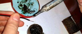
It is very important to use a Pozidriv (PZ) slotted screw. Because in such a slot the needle does not touch the side walls. The length of the screw should be as short as possible so that the magnet is as low as possible. The photo shows a 2x6mm screw.
After tightening the screw, the “wings” are carefully separated and the impeller is given the desired shape.
In order for the magnet to hold well on the screw, you need to screw on another nut. But don't twist it.
Due to the attachment of a neodymium magnet (size 4x4x4 mm), the center of gravity of the impeller rises and it becomes unstable on the needle. To lower the center of gravity, weights need to be glued to the INNER part of the “wings” (washers for a 4 mm screw are used).
The impeller can rotate not only on an awl, but also on VERY WELL sharpened pencils or on a sewing needle attached to a pencil. The impeller spins best on a sewing needle, but this option requires great caution and is categorically NOT SUITABLE FOR CHILDREN.
About anemometers: Beaufort scale - how the points of wind and waves at sea are determined, points during a storm
Dependence of rotation frequency on wind speed (on a mechanical pencil 0.5 mm): 1.5 Hz - 1.4 m/s 4 Hz - 2.85 m/s 6 Hz - 3.4 m/s
DIY anemometer: the simplest diagram
Anemometer is a device for measuring wind speed. The classic cup anemometer is a purely mechanical device capable of measuring wind speed in the range from 2 to 20 m/s. An anemometer simply counts the number of revolutions of the impeller.
To determine the wind speed, you need to measure the number of revolutions over a certain period of time, for example 30 s, and then calculate the number of divisions that the anemometer needle passes in 1 s. After this, you should use the graph to determine the wind speed.
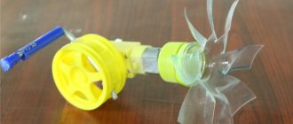
The easiest way to construct its analogue is on the basis of a low-power electric motor, for example DM-03-3AM 3 91, which acts as a generator. The four-bladed anemometer impeller was taken ready-made and purchased on Aliexpress for about $1.
The impeller diameter is 10 cm and the height is 6 cm.
The electric motor is located in a housing made of a cold welding container, in the lid of which a hole is cut for the electric motor shaft and wires leading from the motor.
A VD1 diode bridge assembled using 1N5817 Schottky diodes is connected to the electric motor. An electrolytic capacitor C1 1000 μF x 16 V is connected to the output of the diode bridge.
Installation
We install the device on a high pole on the roof of the house. We calculate what we will do and in what sequence, prepare materials and tools. It is fashionable to make a basting without a device, and then install it. We run the cable into the house and turn on the device. You can see how it works in the video.
Thus, we know how to make an anemometer with your own hands and what is needed for this. It doesn’t matter what the device is used for - ventilation, speed or temperature measurement. It doesn’t matter what it is - stationary, miniature or induction. One thing is for sure - it brings benefits to people.
Video of work
Winter work results
s-st — hours for winter 0 m/s — 511.0 1 m/s — 475.0 2 m/s — 386.5 3 m/s — 321.2 4 m/s — 219.0 5 m/ s — 131.5 6 m/s — 63.3 7 m/s — 32.5 8 m/s — 15.4 9 m/s — 9.1 10 m/s — 5.0 11 m/s — 3.5 12 m/s — 2.2 13 m/s — 1.3 14 m/s — 0.8 15 m/s — 0.5 16 m/s — 0.5 17 m/s — 0, 2 18 m/s - 0.0 19 m/s - 0.1
Based on the results of two winters, I saw that my winds were not strong and the windmill would not be effective, so I made a small one with 50cm blades. peak power 150 W. I just made sure that at least one economical light bulb would shine when the light went out.
Now a little about Arduino.
I found a diagram of how the mouse works on the Internet; it clearly illustrates how my system works.
Based on the mouse diagram, I made the following diagram.
The pulses come from the phototransistor to the Arduino, and it perceives them as button presses.
The algorithm of the program is as follows: We count how many button presses occurred in one second, and here we have the rotation frequency. In order to convert this frequency to m/s. Even when I was doing it on Atmel, I made an algorithm for calculating the frequency in m / s. He looked like this:
int ob_per_sec=0; // Variable that contains the revolutions per second.
int speed_wind=0; // The value will go here after converting the frequency to m/s.
int speed_wind_max=0; // The maximum value of wind readings m/s falls here.
int speed_wind_2=0; // Number of seconds from the start of the program with a wind speed of 2 m/s.
int speed_wind_3=0; // Number of seconds from the start of the program with a wind speed of 3 m/s.
int speed_wind_4=0; // Number of seconds from the start of the program with a wind speed of 4 m/s.
int speed_wind_5=0; // Number of seconds from the start of the program with a wind speed of 5 m/s.
…………………………………………………………..
int speed_wind_22=0; // Number of seconds from the start of the program with a wind speed of 22 m/s.
if (ob_per_sec >0 && ob_per_sec<4) { speed_wind=2; speed_wind_2 ;}
if (ob_per_sec >4 && ob_per_sec<7) { speed_wind=3; speed_wind_3 ; }
if (ob_per_sec >7 && ob_per_sec<11) { speed_wind=4; speed_wind_4 ; }
if (ob_per_sec >11 && ob_per_sec<15) { speed_wind=5; speed_wind_5 ; }
if (ob_per_sec >15 && ob_per_sec<18) { speed_wind=6; speed_wind_6 ; }
if (ob_per_sec >18 && ob_per_sec<23) { speed_wind=7; speed_wind_7 ; }
if (ob_per_sec >23 && ob_per_sec<27) { speed_wind=8; speed_wind_8 ; }
if (ob_per_sec >27 && ob_per_sec<30) { speed_wind=9; speed_wind_9 ; }
…………………………………………………………..
if (ob_per_sec >60 && ob_per_sec<67) { speed_wind=22; speed_wind_22 ; }
if (speed_wind> speed_wind_max){ speed_wind_max = speed_wind ;} // check and rewrite if the maximum value is greater than the previous recorded one.
And display the value on the screen.
speed_wind
speed_wind_max
If necessary, you can then view how many minutes the wind blew at a certain speed; to do this, you need to display the variable (with the necessary speed index) speed_wind_№ (but divide it by 60 to get minutes.).
In my program I did this: when you press a certain button, all the variables are displayed one by one, from speed_wind_1 to speed_wind_22.
First version
No sooner said than done, and thoroughly.
I welded a cross from scraps of polypropylene pipes. I unsoldered all the sensors and extended them with wires that I laid inside the pipes. The distance between the sensors was 70 cm.
The program code is like this.
The last two numbers give the desired horizontal wind speed and direction. The direction is calculated as an azimuth to the north direction and is given in degrees. Rotate clockwise.
Alas, the results disappointed me.
When averaging 25 measurements, readings in calm air jump to an average of 1.5 m/s, with measurements being given approximately once every second. If you average 10 times more readings, the situation improves, but does not fundamentally solve the problem. In addition, judging by the graph of speeds in two axes, one pair of sensors produces significantly more radiation than the other. Most likely the problem is in the wires with which I extended the sensors. We'll have to redo it.
Addition
The anemometer screw, which is not loaded with anything, reacts sharply to every gust and change in wind speed. But the loaded propeller of this wind generator still lags in reactions, and because of this, the data in the readings is not synchronous. Today the wind is 3-7 m/s, the anemometer actually caught a couple of gusts up to 10 m/s, but they lasted less than a second and the wind generator simply did not have time to react to them.
After some time of observation, some average current values from the wind generator were drawn at a certain wind. The propeller starts at 3.5-4 m/s, charging 0.5A at 4m/s, 1A at 5m/s, 2.5A at 6m/s, 4A at 7m/s, 5A at 8m/s. These data are averaged, since the ammeter is an analog ammeter, and I can make an error of up to 0.5A in the current readings from the wind generator.
Source
How to make an anemometer using arduino
The author of this homemade product once faced the question of how one can determine whether there is wind in the place where he lives. This question arose because he wanted to install a wind turbine to generate electricity. Using this ingenious device, you can take measurements of how often the wind blows, at what average speed it blows, and so on. The basis for collecting and processing information is the Arduino board.
Materials and tools for making an anemometer: - a piece of square pipe; - Bulgarian; — welding; — bearing; - scan; - nails; - dye; — LED-phototransistor sensor (can be removed from the printer); — Arduino circuit; - minimum set of tools.
About anemometers: ANEMOMETER • Great Russian Encyclopedia - electronic version
Manufacturing process:
Step one. Making an anemometer sensor
To make a sensor, you need to take a piece of a square pipe and then cut a window in it, through which the filling will then be installed. A metal plate needs to be welded inside this pipe; it will act as a bearing holder. Then another plate is welded to fix the lower bearing.
The author decided to make the top in the form of a pitched roof. To do this, take four triangles, first tack them by welding, and then boil them well.
Next, the workpiece is clamped in a vice and the diameter of the drill is 0.5 mm less than the diameter of the bearing in the bottom cover and a hole is drilled in the middle. Both are needed for bearings. To ensure that the bearings fit into place with tension, the size of the holes is adjusted using a reamer. Once the bearings were installed, a 100-gauge nail was inserted into them. In the middle of the window, a plastic washer with four slots is placed on it. A thread was cut from the bottom of the nail and then the impeller was screwed onto this axis.
Step two. Impeller manufacturing process
To make an impeller you need to take a nut and weld three nails to it with a 2mm electrode. The ends of the nails are trimmed and threaded. Then the halves of the ball are put on the ends.
A hexagonal stainless steel rod was welded to the body as a holder. And to prevent the body from rusting, it was covered with white enamel.
In order for the sensor to read information, you need a washer with slots. The author took it out of an old ball-point computer mouse. When the slot passes in front of the LED phototransistor sensor, it sends a signal to the electronics.
As for the impeller blades, they were first made from tennis balls. With this size of blades, the impeller starts in winds of 5 m/s. To make the impeller more sensitive, balls with a diameter of 55 mm were purchased; in this case, the impeller begins to rotate already at m/s. In this case, measurements are carried out up to 22 m/s.
Step three. Electronic part
As an electronic circuit, the author first used a homemade LUT circuit with the addition of a green maxi from China. But the system could not show wind speed in meters/second. It only displayed the number of revolutions.
At the moment the circuit is being assembled on Arduino. The operating principle of the author's anemometer is exactly the same as that of a computer mouse. Now you just need to connect the two circuits.
It was decided to transmit pulses from the phototransistor to Arduino, and the circuit began to perceive such signals as button presses. To get the wind speed, you just need to count how many button presses there are during a certain time, say, per second.
That's all, now the anemometer can be considered ready. If necessary, you can add a function to the code that would count how long the wind blew at a certain speed. This homemade product will be an excellent addition for those who are planning to install a windmill or closely monitor the weather.
anemometr.rar [9.54 Kb] (downloads: 1118)
Most popular models
The market now offers a wide variety of models of cup anemometers with completely different pricing policies, both foreign and domestic. There are also quite a lot of sites, blogs, video tutorials and examples for making a hand-held cup anemometer on your own.
But, despite the wide choice and the ability to use home-made devices, there are several models that are very often found in various practices for measuring air flow velocities and other additional tasks.
Models that, due to their functionality and ease of use, have gained high popularity among consumers:
- Anemometer RSE-A 420:
Most often found in agriculture and sports. The device is resistant to water getting on the display. Units: m/s, km/h, ft/min, knots and mph. Displays the current, minimum or maximum values.
Automatic shutdown of the device allows you to save battery power. Function for saving the last 100 measurements. Protection degree: IP65. Manufacture: Germany. Warranty: 1 year.
- Skywatch METEOS anemometer:
The device measures the current wind speed, maximum and minimum values. In addition, there are sensors for measuring ambient temperatures and air flow cooling. Units of measurement - m/s, km/h, feet/sec, mph, knots, beauforts.
Measures the average value over a period of time from 3 seconds to a day. Automatic display shutdown – 5 seconds. The degree of protection is IP67, which allows short-term exposure to water at a level of 1 m, and makes it especially popular in the field of water sports. Also often used in industry (in mines, chimneys). Production: Switzerland. Warranty: 1 year.
- Anemometer AM-4836C:
A multi-tasking instrument, as it measures the main characteristics (wind speed), air temperature, as well as the direction of flow, which is possible thanks to the weather vane director that is included with this device. Units of measurement: m/s, km/h, mph, ºC, CFM, CMM.
There is an additional function for calculating volumetric air flow. Backlit display with automatic shut-off. Designed for meteorological and navigation measurements; Widely used in industry (mines, ventilation ducts, heating and refrigeration installations). Manufacture: China. Warranty: to be specified upon purchase.
A cup anemometer is a necessary device that is used in many areas. Despite the impressive “age” of the idea of the mechanism and its principle, the device is modified with each generation, “increasing” additional capabilities in its arsenal.
It is not difficult to assume that in the future the tool will also exist, but what additional features will be included is an open question.
How to make a homemade anemometer (wind speed meter)
How to make a homemade anemometer (wind speed meter)
The task arose to assemble an anemometer for one project so that data could be taken on a computer via a USB interface. This article will focus more on the anemometer itself than on the system for processing data from it:
1. Components So, the following components were needed to make the product: Mitsumi ball mouse - 1 pc. Ping-pong ball - 2 pcs. A piece of plexiglass of a suitable size Copper wire with a cross-section of 2.5 mm2 - 3 cm Ballpoint pen refill - 1 pc. Chupa Chups candy stick - 1 pc. Cable clip - 1 pc. Hollow brass barrel 1 pc.
2. Impeller manufacturing
3 pieces of copper wire, each 1 cm long, were soldered to the brass barrel at an angle of 120 degrees. In the hole of the barrel I soldered a stand from a Chinese player with a thread at the end. I cut the candy tube into 3 parts about 2 cm long. I cut 2 balls in half and, using small screws from the same player and polystyrene glue (with a glue gun), attached the halves of the ball to the lollipop tubes. I placed the tubes with the ball halves on soldered pieces of wire and secured everything on top with glue.
3. Manufacturing of the main part
The supporting element of the anemometer is a metal rod from a ballpoint pen. I inserted a mouse disk (encoder) into the lower part of the rod (where the plug was inserted). In the design of the mouse itself, the lower part of the encoder rested against the mouse body to form a point bearing; there was lubricant there, so the encoder rotated easily. But it was necessary to fix the upper part of the rod, for this I selected a suitable piece of plastic with a hole exactly the diameter of the rod (such a piece was cut from the CD-ROMa carriage ejection system). It remained to solve the problem of ensuring that the rod with the encoder did not fall out of the point bearing, so I soldered a few drops of solder on the rod directly in front of the holding element. Thus, the rod rotated freely in the holding structure, but did not fall out of the bearing. The reason why a circuit with an encoder was chosen is as follows: all the articles about homemade anemometers on the Internet described their manufacture based on a DC motor from a player, CD-ROM, or some other product. The problem with such devices is, firstly, their calibration and low accuracy at low wind speeds, and secondly, the nonlinear characteristic of wind speed in relation to the output voltage, i.e. There are certain problems in transferring information to a computer; you need to calculate the law of changes in voltage or current depending on wind speed. When using an encoder, there is no such problem, since the dependence is linear. The accuracy is the highest, since the encoder gives about 50 pulses per revolution of the anemometer axis, but the converter circuit is somewhat more complicated, which contains a microcontroller that counts the number of pulses per second on one of the ports and outputs this value to the USB port.
4. Testing and calibration A laboratory anemometer was used for calibration:
The whole process is clearly visible on the videos:
Thank you for your attention.
Instrument calibration
A homemade device must be calibrated. It is best to use a vehicle for calibration. But you will need some kind of mast to avoid getting into the zone of disturbed air created by the car. Otherwise, the readings will be greatly distorted.
About anemometers: Magnetic measurements
Calibration should only be carried out on a calm day. Then the process will not be delayed. If the wind blows, you will have to drive along the road for a long time and calculate the average wind speed. It must be taken into account that the speedometer speed is measured in km/h, and the wind speed is measured in m/s. The ratio between them is 3.6. This means that the speedometer reading will need to be divided by this number.
Some people use a voice recorder during the calibration process. You can simply dictate the speedometer and anemometer readings to an electronic device. In you can create a new scale for your homemade anemometer. Only with the help of a properly calibrated device can one obtain reliable data on the wind conditions in the required area.
Source
Bestseller: testo 410-2
Anemometer with impeller
Anemometers in combination with smartphones
Multifunctional measuring instruments
Setting up a homemade anemometer
To adjust the anemometer readings, ideally use a real anemometer. I have held this miracle in my hands only five times in my life. Therefore, I used the standard method, attaching the anemometer to a wooden handle. And when driving a car in calm weather, I set up the bike computer to match the readings with the speedometer.
In my cycling computer, the setting consisted of selecting the value of the wheel radius in millimeters. We remember the value of the found radius (it’s better to write it down), otherwise when changing the battery the computer will forget the settings. The goal was not to obtain super-accurate readings. Everything is set.
Bestseller: testo 410-2
Anemometer with impeller
Anemometers in combination with smartphones
Multifunctional measuring instruments
Anemometer connection diagram
Schottky diodes were chosen due to the fact that the speed of rotation of the impeller, under normal conditions (if there is no hurricane) is not very high. At a wind speed of about 6 m/s, a voltage of about 0.5 V appears at the output of the device. Under such conditions, it is rational to minimize losses on all elements of the circuit. For the same reason, conductors of excessively large cross-sections are used as connecting wires.
You can connect any 2 V DC voltmeter to the rectifier terminals. A multimeter does its job perfectly. Although the use of a separate pointer device allows you to directly calibrate the scale in wind speed.
Since the device was planned to be used outdoors, the diode bridge was cast in epoxy resin. As it turned out, the capacitor was taken to be excessively capacious so that the device could not detect rapid voltage drops and, accordingly, gusts of wind.
Table for determining wind speed by external signs
| wind pattern | wind speed m/sec | signs |
| very light | 0-1 | air movement is imperceptible |
| 1-3 | air movement is barely noticeable, leaves rustle | |
| easy | 4-5 | the branches sway slightly, the smoke floats in the air, maintaining the outline of the clouds |
| moderate | 6-7 | branches bend, the wind “licks” the smoke from the chimney and mixes it into a homogeneous mass, dust rises |
| fresh | 8-9 | the treetops rustle and sway |
| very fresh | 10-11 | thin tree trunks bend, the wind howls in the pipes |
| strong | 12-14 | leaves are torn off, waves are formed on standing water with overturning crests |
| cutting | 15-16 | thin branches break, movement against the wind is difficult |
| storm | 17-19 | thick branches break, tearing off roof coverings |
| strong storm | 20-23 | thin ropes break |
When going to work in the fall and or winter, it is not always clear at night what the weather is like outside, in particular what the wind is like. I think in a strong wind it is useful to dress the children warmly, and not to make a mistake yourself. In case of bad weather, it is also interesting to know the speed of the wind raging outside the window.
Remembering the saying “prepare a sleigh in the summer,” I decided to build an anemometer with my own hands in the summer. There was experience in creating homemade anemometers (wind speed meters), but the designs were created a long time ago on an old electronic base in the 80s of the last century and time has not been kind to them.
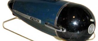
While disposing of another VCR, I decided to leave a trace of it on Earth. All VCRs have a rotating head unit. This is a precision assembly of high accuracy and reliability - the heart of every VCR. The unit is made of stainless metal with a rotating head axis on sealed bearings.
DIY cup anemometer: device diagram
To make a homemade anemometer at home, you will need an old model of a VCR. Its head rotation unit will become the basis of a future design. To do this, excess parts are removed from the assembly to leave only a frame with an axle, a bearing block and a washer for mounting the engine.
- Holes with a diameter of 4 mm are drilled in the rotating part, on which the blade cups will be installed. There are already three holes on one of them - these are the places where the internal components are attached to the disassembled tape recorder. You should navigate by them when choosing places for the remaining nine holes.
- M4 type bolts 10mm long are inserted into the holes. Rubber washers cut from an old bicycle inner tube will help securely secure the cups and prevent them from rotating on the blade axis.
- Now you need to take 4 plastic water mugs of the same size and drill a 4mm hole in the bottom. The handles of the cups are cut off at the root.
- The cups are attached to the axle, turning them in one direction and fixing them with bolts and rubber washers. The fully assembled structure should rotate easily under the influence of even a light wind.
Now you can assemble the structure completely. For this:
- A magnet, another element of the old bicycle, is installed and attached to the rotating part of the assembly. Then the rotation unit is balanced to prevent simultaneous rotation of the pole along with the moving blades.
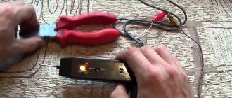
- A mini-computer removed from the bicycle can be used as a counting sensor. It is glued to the stationary part of the assembly, covering the magnet with a sheet of cardboard. It is definitely worth checking the sensor with a tester for speed of response.
- All that remains is to connect the cable and secure a piece of metal corner to the stationary part of the device for subsequent installation of the structure.
Connecting the cable
The sensor cable is extended by 7 meters using a cable for building a computer network. For ease of connection, connectors from fans and the computer power supply are installed on the cable and in the breaks in the signal cable of the bike computer. The cycling computer itself is made in a desktop version, screwed to the magnetic system of the video head motor using copper wire. The result is a stable structure.
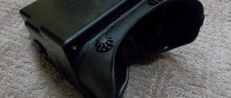
Base
Connector
Desktop option