30.04.2021
I’ve been wanting to build my own Arduino board for a long time, I looked at the diagrams, but I never got around to it. There were several reasons:
- My laptop does not have a COM port, so the version with a COM port does not suit me
- The USB version uses a very expensive FT232R chip
Well, one day I came across an article on Habré, where they used an AVR converter instead of an FT232R (there is no circuit diagram there), as well as a similar implementation on Zelectro, but on an Atmega8 microcontroller. The latter was made on the basis of a Japanese project. This is what inspired me to make my own Arduino implementation.
And so, if you go to the AVR-CDC website and look at the latest changes (in the archive with the firmware, there is no information on the site), then Rx Tx lines are implemented there, as well as DTR, CTS, RTS, not only on the relatively expensive ATMega8, but also on cheap AtTiny2313. The last lines only work on quartz at 16 or 20 MHz. It was on the basis of this chip that I decided to build a USB - UART converter.
- Firmware AtTiny2313 for quartz 16 MHz -
- USB driver -
- Fuse bits - HFuse: CD; LFuse: FF
The Arduino part was taken from the official website with virtually no changes.
The board is powered from both USB and external power. The board has a standard connector for the AVR910 programmer for flashing the main chip. In my case it is AtMega8, but you can also use AtMega168.
To operate the AVR910 programmer, you must add the following lines to the programmer configuration file..\Arduino\arduino-1.0.6\hardware\arduino\programmers.txt:
Avr910.name=avr910 avr910.protocol=avr910 avr910.communication=serial avr910.speed=115200
The above file can only be edited normally using the Notepad++ editor. It looks unreadable in regular Notepad.
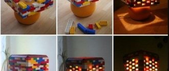
Below is a photo of this Arduino assembled by Pavel!
Homemade USB Arduino with programmer
Good afternoon. With the advent of arduino, robotics, automation and other radio products have become more accessible to us. Previously, it was difficult to imagine that it was possible to write firmware for microcontrollers with such simplicity, with the advent of arduino
Even kids can do robotics.
Arduino
platform allows you to forget about bitwise operations and avr registers that were used everywhere. But since the platform is universal, the microcontroller is also chosen to be universal. For example, the arduino uno provides an atmel atmega328p, which is unnecessary for simple processing of button presses, and if you make a batch of devices at once, you will have to pay for the unused power.
But since the arduino ide is freely available, anyone can easily write add-ons and libraries, and they can often be very useful. This article will talk about a library of boards based on ATmega8, ATmega48, ATmega88, ATmega168 called Mini Core.
This library will allow you to write arduino sketches for weaker microcontrollers than atmega328p, and this allows you to reduce the cost of the device due to the rational use of power.
Why these microcontrollers:
- These microcontrollers have the same pins and architecture and have minimal differences from atmega328p (replaceable)
- They are cheap and popular(some are less than a dollar)
- They all have DIP and TQFP packages
This library supports all chip indices except PB (i.e. A, P, PA), for example, you should not use ATMEGA168PB-AU.
Microcircuits by characteristics:
| Atmeg328 | atmega168 | atmega88 | atmega48 | atmega8 | |
| Flash | 32 kb | 16 kb | 8 kb | 4 kb | 8 kb |
| RAM | 2 kb | 1 kb | 1 kb | 512 b | 1 kb |
| ROM | 1 kb | 512 b | 512 b | 256 b | 512 b |
| PWM channels | 6 | 6 | 6 | 6 | 3 |
It’s time to move from theory to practice, let’s install Mini Core; for installation you will need Arduino IDE version 1.6.4 and higher. If you don’t have an Arduino or it’s older, download it from the office. Site.
1. To install, do the following:
2. Launch Arduino IDE
3. Open the menu File ⇒ Settings.
4. After the above operations, close the settings and go to the menu Open the menu “Tools” ⇒ “Board:………”” ⇒ “Board Manager...”.
5. In the board manager, select our library and click install:
Note
. If you are using Arduino IDE 1.6.6, you may need to close the Board Manager and then open it again.
After installation, in the menu “Tools” ⇒ “Board:”………”” options for boards with our microcontrollers will appear.
The most convenient option for using these microcontrollers is to take an arduino uno with a chip in a dip package and replace it with the desired one. You can also assemble a board with simple wiring:
For those who need pinout of microcircuits, photo below:
Another important feature is that the authors added the ability to select a quartz resonator at several frequencies and power control parameters, which are not available by default for standard boards. All manipulations with these parameters are performed in the tools menu.
Clock settings:
- 16 MHz external oscillator (default)
- 20 MHz external oscillator
- 18.432 MHz external generator *
- 12 MHz external oscillator
- 8 MHz external oscillator
- 8 MHz internal oscillator**
- 1 MHz built-in oscillator
Do it yourself using the ATmega328p IC microcontroller. As a result, you will be able to understand how to make analogues of any boards in the future, plus create your own. Maybe you will even open your own company producing boards and microcontrollers.
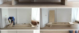
Since Arduino is an open source platform, it is quite easy to learn about the innards and details of everything that makes Arduino what it is. So in this tutorial we will look at the Arduino Uno circuit, modify it a little according to our needs, make a PCB for it and solder the necessary components to create the final product.
We will not use any SMD components to create our version because not everyone has a soldering station and sometimes it is very difficult to find SMD components. Moreover, our method is cheaper than SMD components in most cases. For those who are just starting to understand electronics, surface mount technology of printed circuit boards is also called TMP (surface mount technology), SMT (surface mount technology) and SMD
-technology (from the English surface mounted device - a device mounted on a surface), and
components
for surface mounting are also called “chip components”.
First of all, let's talk about the changes we are going to make to the original Arduino Uno circuit, which you can see above or download below.
The changes will be as follows:
- We will not use any SMD components. All elements will be in through-hole format.
- We haven't found any FTDI chips in through-hole format, so USB to TTL conversion won't work. A separate FTDI development board will be used to program the new Arduino.
- The original Arduino uses a Mosfet comparator to determine whether we are connecting the board using a USB or DC power supply. But in our version we will manually switch this using a jumper.
- Traditionally, the LP2985 IC from Texas Instruments is used to provide the 3.3V power supply on board. But due to the unavailability of the board in TH format, we will use a simple linear regulator. So the LM1117 should be the obvious choice, but to keep the manufacturing cost even lower, we'll use the LM317 with R1 and R2 as the 240E and 390E respectively.
- The last thing the board needs is enough power lines and two headers for each IO port. Therefore, we will place a series of male and female connectors around the board, which will help connect more devices directly to the Arduino.
Taking into account all the changes, we can write down the final list of components.
What kind of Arduino
Arduino is a programmable microcontroller. That is, this is a board on which you can write your program, and this board can control other things: for example, light a light bulb, make a sound, turn on an electrical appliance, measure temperature, send SMS.
At its most basic level, the Arduino simply sends and reads electrical impulses. For example, you can connect a thermometer to it, and the Arduino can read the temperature in the room. And then, depending on the program, send a signal to the device, which will turn on the fan.
Or you can connect a carbon dioxide sensor to the Arduino. Arduino can be taught to read the sensor every five minutes and, when the level of carbon dioxide exceeds the norm, beep, flash a light, or use a series of motors to open a window.
How to program Arduino
There are many expansion boards and sensors for Arduino. The board's applications are almost limitless: automation, security systems, smart home, music, robotics and much more. Here's what you can do on this smart Italian board and on its Russian and foreign clones.
Arduino projects on the Internet
On the Internet you can find a huge number of examples of various projects with Arduino. We have made a small selection of the most unusual projects.
Today you can easily find hundreds of projects created by the hands of enthusiastic engineers around the world. It is impossible to do a quality review of all of them. In this collection we just made a short review
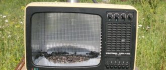
Controlling your TV with your thoughts and Arduino.
Controlling a TV with the power of thought and Arduino
This original project seems incredible, because to change the channel you don’t need a remote control, but the thought of changing it. To create, you will need an Arduino Uno, the Star Wars Force Trainer game, an infrared receiver and transmitter.
The project was carried out by Daniel Davis at home. He took the 2009 game Star Wars Force Trainer as a basis and disassembled it. The game itself contains a headset that can detect electrical fields of the mind (similar to EEG). Inside was a NeuroSky EEG chip, which Daniel connected to an Arduino board. EEG data is collected and converted on a computer.
Using a serial monitor, you can view the signals that the remote control transmits to the IR receiver when switching channels. Next, the button code is written down and a small program is written.
After completing the programming part, the person is put on a helmet and can switch the TV cables and turn it off by focusing their thoughts.
A mechanical hand that writes time on a board.
Mechanical arm that writes time on a board
Plotclock is a simple robot that consists of a hand with a marker that writes the current time on a board. When the time changes, the hand erases the previously written number and writes new values. The project is constantly evolving, the technology described is the simplest.
To implement the project, you need a 3D printer, Arduino Uno, 3 servos, bolts and nuts, a whiteboard marker, and a white surface.
The mechanical component of the robot is made of plastic elements and interconnected mechanisms. The arm is controlled using an Arduino board and three servo motors.
Ok Google, Sesame, open the door
Hey Google, Sesame, open the door
The project implements opening a door using a specific voice command. To enter the room, just say the phrase “Open Sesame.”
To create it you will need an Arduino Uno, a servo motor, and a Bluetooth module.
Google Now commands are used to unlock the door. For smartphones and tablets there is an application called “Sesame”, which sends a command to the door lock when the words “Okay Google, Sesame, open” are pronounced.
The servomotor is connected to the door lock. The Bluetooth module waits for a command, and when it receives it, it sends a signal to the Arduino via the serial port. The Arduino Uno issues a command to the servo and the door opens.
LED cube 4x4x4.
LED cube 4x4x4
An Arduino-based LED cube is an entertainment lighting device. It can be of different sizes with different backlight modes. The cube is equipped with a mode switch button.
To create, you will need 64 LEDs, 4 100 Ohm resistors, conductors, a breadboard, connectors, a box, a 9V power supply and an Arduino Uno board.
A sketch of a 4x4 square is drawn or printed on the box. Holes are made into which LEDs are placed. The anodes need to be connected to each other, then the box needs to be turned and the diodes pulled out. 3 more layers are formed in the same way. All layers must be connected using the remaining cathodes. The resulting cube is placed on the breadboard and connected to the board.
Robot vacuum cleaner
Robot vacuum cleaner
Using Arduino, you can create a useful thing for your home - a robot cleaner. A self-made model will not be inferior in its characteristics to a store-bought copy.
For assembly you will need:
- Arduino;
- L298N driver for motor control;
- miniature motors with gearbox and wheels;
- 6 infrared sensors;
- engine for turbine;
- turbine;
- motors for brushes;
- collision sensors;
- 4 batteries;
- step-up and step-down current converters;
- battery controller.
The vacuum cleaner is equipped with IR sensors. They react when the vacuum cleaner approaches an obstacle and command it to stop and turn around. When colliding with a wall or other obstacle, one of the switches connecting the bumper and the robot body is activated.
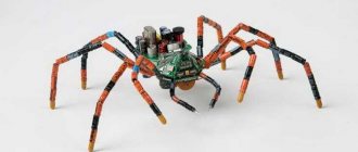
Facial recognition and tracking system on Arduino.
Facial recognition and tracking system on Arduino
The webcam is mounted on a rotating mechanism and connected to a PC on which OpenCV software is installed. When the program detects a face, it begins calculating its center point. The resulting coordinates are transmitted to the Arduino microcontroller, which controls the servos and monitors the face.
For implementation you will need:
- software Arduino IDE, OpenCV;
- Arduino Uno board;
- 2 servomotors;
- Webcam.
Automated system for aquarium
Automated Aquarium System
Automating aquarium tasks helps make the user's life easier. The project must be responsible for the following activities:
- supply of backlight of one color or another depending on the conditions;
- time display;
- compressor regulation;
- turning filters on and off;
- displaying data on temperature, humidity.
To assemble the device, you will need an Arduino Uno board, a piezo signal, an RGB strip, a white diode strip, a temperature and humidity sensor, an LCD screen, a clock, 2 relays, an IR receiver, and transistors.
There are many schemes for implementing the device. An example of one of them is given below.
You also need to write a code to turn on one color or another depending on the conditions and configure the operation of the LCD screen.
Greenhouse for plants
Greenhouse for plants
In a smart greenhouse for flowers, temperature and lighting are monitored and adjusted, and the soil is watered. This is especially true for heat-loving tropical plants, in which it is necessary to constantly maintain a high temperature. You can control it automatically or remotely from a tablet or smartphone.
To assemble the project, you need the following components:
- Arduino Uno;
- USB cable;
- prototyping board;
- wires;
- photoresistor;
- 10 kOhm resistor;
- temperature sensor;
- ambient temperature and humidity module;
- soil moisture module.
The photoresistor is responsible for measuring illumination. The temperature sensor receives the air temperature. The soil moisture module is placed in the ground and measures the water level in the ground.
Real-time tracking of electricity consumption using Arduino and LabVIEW.
Monitoring electricity consumption in real time using Arduino and LabVIEW
The device can be used in a smart home as a meter for electricity consumption on modern meters. The information is read through the counter LED - the duration between blinks is calculated.
The operating principle is as follows. Arduino reads the blinking frequency and provides information via the wireless module. A module installed on the computer receives this data and transmits it to LabVIEW, which displays power consumption data in real time.
The blinking of the LED is detected by a photoresistor. Analog data is read using a voltage divider.
To work you will need:
- Arduino;
- photoresistor;
- Light-emitting diode;
- Xbee module;
- Arduino IDE, LabView software;
- simple and tuning resistors;
- wires.
The program will display a consumption graph for the last 5 minutes and in real time.
Audio player
Audio player
You can create an audio player using Arduino with your own hands. Its design is simple - it consists of a speaker, a transistor, a micro-SD card with tracks recorded on it. Arduino is used as a board; you can also take a Seeeduino 2.21 or Garagino controller on ATmega328.
For assembly you need:
- controller;
- card reader;
- speaker;
- printed circuit board;
- memory card with recorded audio tracks;
- transistor;
- resistor;
- wires.
The player works as follows. Arduino loads files with the .wav extension of the memory card. A signal is generated, which is output through speakers connected to pin 9 on the board.
The song must first be converted to .wav format. This can be done using the simplest online converter. Music files have limitations when playing melody. The transistor will not be able to read complex .wav files, so it is recommended to convert the tracks to the following form: 16 kHz per second, mono channel, bits per sample - 8.
Music is recorded on a pre-formatted memory card and saved with simple names. After collecting the circuit, you need to write the code, turn on the power, after which the music will start playing.
Recommendations for working with Arduino projects on the Internet
Having found a project that interests you on the Internet, first try to understand its operating principle. Look at how the elements are connected, what functions they perform, and what the limitations are. Try to first create a prototype of the device (an electronic circuit with firmware) and only then try to completely repeat what you see in the description.
Robot bartender with Bluetooth control
Complexity: 4/5.
Time: 5/5.
An indispensable device for any party: it runs on eight batteries, prepares a lot of cocktails and is controlled wirelessly. The mechanical bartender is based on an Arduino board, drives for positioning the shaker and serving drinks, and position sensors.
The main difficulty in manufacturing is engineering. You need to accurately screw all the parts and connect them together so that the container is exactly under the desired bottles.
Details: usamodelkina.ru.
Connection diagram
Next we are going to connect the Arduino Mega to the servos and the coin machine, and then test our vending machine. It's best to wire up the entire system outside of the cabinet first to make sure everything works before putting all the parts into the vending machine.
Below you can download the schematic file for the Fritzing program:
Glowing cube with 512 LEDs
Complexity: 3/5.
Time: 3/5.
A beautiful thing that can glow in time with music like a 3D equalizer and show 3D animation. It can also work as an unusual night light.
To assemble, you will need a wooden chassis with holes in it so that each tier is the same size and shape as the others. The number of LEDs in each face was not chosen by chance: 8 lamps = 8-bit logic, the easiest to program and control via a controller.
Details: instructables.com.
Assembling parts
You can order the Venduino body kit through Ryan Bates' website (https://www.retrobuiltgames.com/diy-kits-shop/venduino/) and the LCD screen cover through thingiverse.com (https://www. thingiverse.com/thing:3306469). Creating a housing for a vending machine from a kit is quite simple - follow the photographs that come with the kit or on the website.
There is one customization we are going to do for the 2.8 inch TFT LCD screen, the original screen size is much smaller than our LCD screen. So use a hand tool to cut a 2.35″ by 1.75″ square around the original hole that will fit our TFT LCD screen.
Next we need to create the wire spools that hold the items in the vending machine. You can use decorative wire because it is easy to work with. Next, take a cylinder (slightly smaller than a can of cola) and wrap the decorative wire around it six times. Then we cut the wire. Use the remaining pieces to attach decorative wire to the servo (see photo below).
Code lock burglar
Complexity: 5/5.
Time: 4/5.
This project was developed by hacker Samy Kamkar and is provided for demonstration purposes only. For hacking, in addition to the Arduino board, the author took servo and stepper motors to try combinations and connected everything on a homemade aluminum chassis. The algorithm is based on a simple search of all combinations, but the robot does it faster than a human.
Details: YouTube.
What is Arduino and what can you do with it
Arduino is a small printed circuit board that has its own processor and memory module.
Conceptually, this is an electronic designer that allows you to create an infinite number of devices. The presence of contacts on the controller makes it possible to connect various components: sensors, lamps, motors and any devices powered by electricity.
The Arduino project was first proposed in 2005 to students at the Italian Institute of Interactive Design Ivrea. The developers were faced with the task of providing a low-cost and simple way to create devices that can interact with the environment. Today, robots, detectors, thermostats and any projects that the imagination of programmers and engineers are capable of are created on the basis of Arduino. Even beginners can develop devices based on Arduino.
The device is controlled by a program executed by the board's processor. Such programs are written in C++ in the official Arduino IDE programming environment, implemented for Windows, MacOS and Linux. Even in the absence of skills in developing and designing electronic circuits, a person can get used to the software environment in a couple of weeks and begin creating simple devices.
Nod Bang - nod your head and make a beat
Complexity: 2/5.
Time: 3/5.
The idea is not just to nod to the beat of the music, but to generate the sound yourself with your nods. Andrew Lee made a special device that monitors the position of the head and plays the desired sound when tilted.
He built an accelerometer into the headphones, the buttons are responsible for selecting the sound, and the Arduino is responsible for playing the sound on the computer via a MIDI interface. To make everything look more impressive, the buttons are backlit, and they also make a beat.
Details: YouTube.
Board manufacturing
1. So, I have prepared the template, all that remains is to print it on film. As I wrote above, I need a film for a printer, I tried the film for both a laser printer and an inkjet printer, the best option is obtained only with film for inkjet printing. You need to print in negative and mirror image:
I immediately laminated the template so that fingerprints and debris could be easily washed off. 2. Next we need to sand our future board (fiberglass laminate). A slightly dampened regular sponge or melamine sponge is suitable for this:
3. After this procedure, the copper still needs to be degreased with acetone:
As you can see in my photo, I degreased it with a regular napkin, and I poured the acetone into a peroxide bottle, it’s more convenient to take it... 4. The next step is to cut the photoresist for your future board slightly with a margin and carefully remove the top protective film so as not to damage it. If the photoresist is domestic, you need to peel off the matte side, if it is Chinese, then there is no difference... 5. Next, glue the photoresist onto the PCB so that air bubbles do not appear under the photoresist, otherwise the tracks will not appear in such places, cut off the excess... The process of gluing the photoresist is similar to gluing protective film for the phone.
6. When the photoresist is glued, the textolite with it must be passed through a laminator 2-3 times or use a warm iron and ironed through a sheet of paper folded in half:
The main thing is not to overheat the photoresist, otherwise it will turn out like this:
If you get a “jamb” when gluing the photoresist, then it’s better to remove it (wash it off or scrape it off) and re-glue it, otherwise after etching the board it will be sad... I won’t remove this photoresist, I’ll show you the end result. 7. Place a template on the PCB with photoresist and press it with glass (I took it from an old photo frame), and place a weight on the glass: 8. Illuminate the photoresist using a UV lamp. My lamp lasts about 2 minutes: As you can see, the photoresist that was illuminated changed color from light blue to dark blue, and the illuminated photoresist is very fragile. 9. Remove the glass and template. Excess photoresist can (optionally) be trimmed and carefully separated with tweezers:
10. The next step is to wash off the undeveloped photoresist with alkali; to do this, take 2 glasses of water and a tablespoon of soda ash, stir well. Peel off the top protective film of the photoresist and dip our textolite into an alkaline solution. 11. We take a brush and rub the photoresist in the alkali, gradually the undeveloped photoresist is washed off: The alkali can not be poured out, but left on the next board or to wash off the photoresist after etching, but more on that a little later... 12. Etching the board: There are two most accessible methods: etching with ferric chloride or peroxide + citric acid and salt. I won’t write about ferric chloride, but I’ll probably describe it using peroxide: - 100 ml. hydrogen peroxide 3% - it is sold in a pharmacy for 7-12 rubles - 30 g. citric acid (available in any grocery store) - 1 tbsp. spoon of salt (both fine and rock salt will do)
All this is mixed in a container and the board with the finished photoresist is immersed there, after a while bubbles appear on the board: And after a while the “bare copper” is completely etched:
By the way, if you etch at a higher temperature, for example with an incandescent lamp or in a water bath, then the etching will be reduced by three, the main thing is not to overdo it, otherwise the excess will be etched... 13. It is most convenient to remove the photoresist in the same alkali in which the unetched photoresist was washed off, minutes later 20 it will fall off on its own and you don’t need to rub anything...
And here are my “jambs”: Although not significant, it’s all due to inattention, I didn’t notice air bubbles under the photoresist or it overheated...
I got the following board “clean”:
14. Next, we drill holes and tin the board: 15. Solder all the parts and wash off excess flux:
I soldered SMD components with a Chinese infrared soldering station, very convenient:
That's all, the hardest part is over, all that remains is to test the tracks for short circuits and start programming the chip.
Singing plant
Complexity: 2/5.
Time: 2/5.
Essentially this is a theremin made in the form of a plant. All other operating principles remain the same: sound occurs when the hands move, and different movements generate different melody.
The board registers changes in signal amplitude, for which the author uses a homemade touch detector to analyze touches to a flower. In addition, we needed a Gameduino expansion board and the flower itself.
Details: Vimeo.
How to make a smart home using Arduino with your own hands
Creating a smart home using Arduino with your own hands is not much different from developing and implementing any other electronic system. The process includes several mandatory steps.
Development of a preliminary design
Expert opinion
Yakovlev Alexey Sergeevich
Electrician with 20 years of experience and extensive experience
At the first stage, a detailed design of the future system is drawn up. When creating a system for your own house or apartment, the owner acts as both a customer and a contractor. Accordingly, this stage includes the preparation of detailed technical specifications and preliminary design.
Accordingly, the developer will have to solve several problems.
Task formulation
The task for the project must be defined as accurately and in detail as possible. For example, one of the private home automation solutions is to turn on the porch lighting when a person approaches it in the dark. This general description of the problem needs more specific formulations for design purposes.
They describe:
- The main conditions for triggering automation are triggers in home automation terms. In the problem under consideration, there is only one such trigger - the person approaching the porch.
- Additional conditions. They set permissions for the trigger to fire and, in most cases, determine the duration of their action. For this task, an additional condition is darkness. Indeed, it makes no sense to turn on the porch light during the day. There is no need to do this even when the porch is lit - the light is already on or other sources are involved. Accordingly, additional conditions can be set in several ways: it is dark and the porch light is not turned on. An almost complete description of the conditions, but does not take into account the possibility of lighting from other sources; the illumination on the porch is below the threshold value. Although the condition looks simpler, it takes into account almost all cases.
- Actions. Describes the system's response to triggers and additional conditions. For the current example, the system must perform a single action - turn on the light.
- Actions in case of missing triggers and/or non-fulfillment of conditions. Here it is necessary to consider 2 cases: neither the main nor additional conditions were met. The most logical behavior is inaction, the trigger and conditions were met, the trigger occurred, then the situation changed (the so-called post-action action). The behavior of the designed system should look like this: do not turn on the light until the trigger is triggered and the conditions are met, turn it off after it is no longer needed.
Thus, the result is a detailed description of the task:
- Check to see if there is a person at the porch.
- Do nothing while he's gone.
- If a person approaches, check the lighting.
- If it is below the specified value, turn on the light.
- Check to see if the light is still needed.
- If yes, stay in the current state; if no, turn off the light.
Choosing ways to implement the algorithm
At this stage, a set of sensors is defined to receive data (triggers and conditions) and actuators to perform actions.
Even in the simplest case under consideration, several implementation options are possible. For example, you can determine the presence of a person at the porch:
- based on a signal from a standard infrared sensor;
- by placing sensors that respond to pressure under the porch platform (for example, strain gauges based on the piezoelectric effect);
- receiving a signal from the Wi-Fi router operating in the apartment that a new/specific subscriber is connecting to the home wireless network, etc.
Situations with determining the level of illumination and turning on the light on the porch are considered in a similar way.
Another mandatory point that needs to be taken into account at this stage is the definition of data exchange between devices. Several options are also possible here - exchange via signal wires, wireless signal transmission (in this case, you will need to select the appropriate standard, for example, BlueTooth, Wi-Fi, ZigBee, etc.).
The stage is completed by recording the algorithm taking into account the decisions made, for example:
- Interrogate the wired IR sensor.
- If there is no signal, do nothing.
- When a signal appears, check the condition of the wired light sensor.
- If there is a signal, do nothing.
- If there is no signal, issue a command to the ZigBee hub to turn on the switch at the appropriate address (responsible for lighting on the porch).
- Interrogate the IR sensor.
- As long as there is a signal (a person on the porch), do nothing.
- If there is no signal, turn off the light, i.e. issue a shutdown command to the ZigBee switch.
- Return to the beginning of the cycle.
Another result of this stage is a list of necessary equipment and materials. To assemble the system you will need:
- A controller with the ability to poll wired communication channels (at least two, for the light sensor and the IR sensor).
- ZigBee switch.
- ZigBee hub (you can do without it if the controller has an interface for direct control of ZigBee devices).
Expert opinion
Yakovlev Alexey Sergeevich
Electrician with 20 years of experience and extensive experience
We should not forget about wires for laying signal lines, power supplies for all devices, and possibly repeaters or signal amplifiers if the distances are large. The best option to formalize the results of the stage is to draw up a block diagram of the system and a block diagram of the algorithm. This will greatly simplify the work in the future.
Equipment selection
After drawing up a structural diagram of the project, you can begin to develop a fundamental diagram, which, first of all, includes the choice of equipment.
Selecting an Arduino controller
Since the base platform, Arduino, was previously defined, all that remains is to select a specific controller model and, if necessary, an extension. The task is not difficult, since the range of devices is quite extensive and includes models for most practical tasks.
The list of equipment includes:
| Controller | Chip | Memory (RAM/ROM) | I/O ports and interfaces | Additionally |
| Due | 32-bit Cortex-M3 ARM SAM3U4E, 84 MHz | 64+36Kb/256+256Kb (direct addressing of the entire space is possible) | 54 digital IOs (some with special functions such as PWM) 12 analog inputs (with ADC) 2 analog inputs | Controller power supply 3.3V |
| Uno | 8-bit ATmega328 or ATmega8U2 (new version), 16 MHz | 2Kb/32Kb+1Kb EEPROM | 14 digital IOs (6 can be used as PWM) 6 analog inputs with ADC UART TTL USB Connectors for expansion modules | |
| Leonardo | 8-bit ATmega32u4, 16MHz | 2.5kB/32Kb+1Kb EEPROM | 20 digital IOs (7 with PWM functions) 12 analog inputs (can work as digital) USB extensions | Built-in USB support allows you to customize visibility when communicating with a PC (like keyboard, mouse, virtual serial port) Functionally and structurally similar to Uno |
| Duemilanove, Decimila | 8-bit ATmega168, 16MHz | 1Kb/16Kb+512B EEPROM | Otherwise completely similar to Uno based on ATmega328 | |
| Mini | 8-bit ATmega168, 16MHz | 1Kb/16Kb+512B EEPROM | 14 digital IOs (6 can be used as PWM) 6 analog inputs with ADC | MiniUSB adapter required for programming Compact prototyping solution |
| Micro | 8-bit ATmega32u4, 16MHz | Compact controller, similar in functionality to Leonardo, uses a microUSB cable for connection and programming | ||
| Nano | 8-bit ATmega168 or ATmega328, 16MHz | Compact version of Duemilanove, differing only in size and lack of a connector for connecting an external power source | ||
| Mega | 8-bit ATmega1280, 16MHz | 8Kb/128Kb+4Kb EEPROM | 54 digital IOs (14 with PWM functions) 16 analog inputs with ADC 4 UART ports USB extensions | |
| Mega 2560 Mega ADK | 8-bit ATmega2560, 16MHz | They differ from Mega by increasing the ROM volume for storing programs to 256 KB and implementing a USB interface on ATMega8U2. Mega ADK is configured with a USB host that can work with other devices, in particular smartphones | ||
| Pro | 8-bit ATmega328, 16MHz (3.3V) or ATmega168, 8MHz (5V) | 2 or 1 KB/32 or 16 KB + 1 KB or 512B EEPROM | 14 digital IOs (6 can be used as PWM) 6 analog inputs with ADC UART TTL USB Connectors for expansion modules | I/O connectors and interfaces are not installed, the developer can use his own |
| Pro Mini | Similar to Mini, but like the full-scale Pro, requires installation of connectors |
Attention! To work with boards that do not contain built-in USB interfaces, use Adapter Mini USB or USB Serial Light Adapter.
In addition to standard controllers, specialized ones with additional interfaces on board have been developed and supplied:
- Yun is a device similar in capabilities (chip, pins) to Leonardo, but with a built-in Wi-Fi module based on Atheros AR9331.
- BT is a platform with a built-in BlueTooth interface.
- Fio is a controller similar to Uno in functionality, but without installed connectors on the I/O ports. Designed to work in a ZigBee wireless network.
- Serial – functionally similar to the basic Uno with an integrated standard RS232 serial interface.
In addition, standard expansion cards can be used to work with various communication standards and devices:
- Wi-Fi with support for 802.11 b/g protocol;
- Xbee Shield , with integrated Maxstream Xbee Zigbee module supporting up to 32 ZigBee devices (35/90 m indoor and outdoor respectively);
- Ethernet Shield – with an installed Ethernet 10/100 Base-T port for a wired network connection;
- Motor Shield – with ports for controlling DC motors and receiving feedback signals from position sensors.
If necessary, you can find other configurations of fully compatible controllers produced by third-party developers. A complete list of approved equipment is available on the official website https://playground.arduino.cc/Main/SimilarBoards/.
When choosing a controller you need to consider:
- Performance;
- Availability of the required number of input/output ports, digital and analog;
- Amount of memory for storing programs and data (all Arduino boards use poor microcontroller resources and do not require extensions);
- Ease of operation - programming, debugging programs, installing a finished device into the case.
To solve the problem under consideration with porch lighting, a compact Micro, Nano or Mini is quite sufficient, but the basic Uno is much more convenient to work with. In addition, you will need an Xbee Shield expansion card to work with ZigBee devices.
Peripheral selection
There are no significant restrictions when choosing sensors and actuators. The only requirement is to ensure compatibility with Arduino ports in terms of signal levels and load.
However, if desired, this requirement can be easily overcome by assembling your own or using ready-made matching boards.
Development of a schematic diagram
After purchasing the controller and peripheral devices, you should draw a schematic diagram of the automation system. With Arduino boards this will not be difficult; the main task of the developer is to select the pins of the input/output ports for connection - this is important information for writing a program.
For your information! Changing conclusions at the program development stage is not difficult - just adjusting just 2 lines of code is enough.
Working with the software
When the circuit diagram is ready, the most important design stage begins - writing a program for the controller. To do this, you need to download the Arduino IDE development environment.
Downloading, installing, checking software
The software can be downloaded from the official website https://www.arduino.cc/en/software.
Stable version – Arduino IDE 1.8.13 supports:
- Windows 7 and newer OS versions, x86 and x64;
- MacOS 10.10 and later;
- 32- and 64-bit versions of Linux and Linux ARM.
To work under Windows, you can download the installer or ZIP archive of the software. It is preferable for inexperienced users to use the installer - the drivers will be installed automatically along with the installation of the program.
When using a ZIP archive, you just need to deploy the program on your PC's hard drive and run the IDE. In this case, the program will also try to install drivers, but you may have to update them manually in the Control Panel. All necessary .inf files are included in the package.
For your information! Experienced users can try the beta version of Arduino IDE 2.0 with improved functionality, support for Win 10, 32-bit or 64-bit Linux systems, MacOS 10-14.
Features of the Arduino IDE development environment:
- Creation of projects (sketches, from the English sketch - sketch).
- Checking them and compiling them for loading into the controller;
- “Uploading” ready-made machine code into controllers;
- Support for all board versions;
- Connecting libraries not included in the package.
After installing the software, you should check the functionality of the purchased controller and the integrity of the software.
To do this, just complete the simplest sketch included in the delivery package with LED control.
The step-by-step process is as follows:
- Connect the Arduino Uno board (this is what we chose to implement the proposed task) with a cable to the USB port of the computer.
- Launch Arduino IDE.
- In the development environment, open the finished sketch - in the File menu, select the Examples-1.Basic folder, in it the Blink file.
- Select the controller board to work with – Tools-Board menu.
- Specify the port for communication with the board (usually COM3 or another COM with a higher number). If these ports are not present, you should check whether the board is connected or install the drivers manually.
- Compile the sketch through the Sketch-Verify/Compile menu or by clicking on the corresponding button in the toolbar under the menu bar.
- Upload the finished sketch to the controller (Sketch-Upload) or by clicking the toolbar button. At this stage, you can observe the blinking of the Rx and Tx LEDs, which indicates an exchange with the PC.
- After the boot is complete, the LED on the Uno board will start blinking after a few seconds. This indicates that both the controller and the development environment are fully functional.
Attention! If the sketch does not load, you should press the Reset button on the controller board and repeat the loading procedure. You should do the same before each new boot, especially on Mini boards.
After verification, you can begin to develop your own program.
Sketch programming
Sketch programming can be done directly in the development environment editor or in any other convenient text editor (in the latter case, do not forget to save the work in the .ino file). The built-in Arduino programming language is a clone of the C++ language with some simplifications and additional functions and libraries for accessing the functionality of the controller.
To work with the program in the IDE you must:
- Create a new sketch (File-New).
- Connect the necessary libraries. Standard function libraries are included in the package, non-standard ones must be placed in the appropriate folders of the Libraries folder. After this, their names will become available to the developer in the Sketch-Import Library menu. Simply select the names you need, and they will be included for processing by the preprocessor.
- In the setup() function, specify all the necessary actions to initialize the system. This function is executed once before start. As a rule, in its text it is enough to confine itself to assigning functions to I/O pins.
- In the loop() function, write the code that implements the automation algorithm - polling sensors, analyzing conditions, issuing signals to actuators. The function is executed in an endless loop; there are no interruption operators for this loop.
- Compile the written sketch.
- Upload it to the controller.
Differences between the Arduino language and the C++ standard
- There is no need to include header files (headers, files with the .h extension) in the program text; the preprocessor will add them automatically in accordance with the libraries imported for the sketch.
- Added predefined constants for levels (HIGH and LOW) and I/O port pin functions (INPUT and OUTPUT).
- Added functions for working with: digital input/output ports pinMode(), digitalWrite(), digitalRead();
- with analog pins analogReference(), analogRead(), analogWrite();
- additional IO functions, for example, bitwise output with shift shiftOut();
- time mills() – time in ms, micros() time in µs, delay() – delay in ms, delayMicroseconds – delay in µs;
- external interrupts attachInterrupt() and detachInterrupt();
- serial port.
Otherwise, the language standard is fully supported, including compiler directives, constants and data types, operators (including unary), and functions.
All controller and expansion boards come with the necessary libraries to work with all hardware. In addition, there are thousands of ready-made community-developed libraries available online. You can find the one you need (with documentation) using the links on the official website https://playground.arduino.cc/Main/LibraryList/ and https://www.arduinolibraries.info/ or on GitHub.
Accordingly, to implement the task, the developer needs:
- Create a sketch.
- Download and connect the library for working with Xbee (ZigBee).
- Assign ports for polling sensors in the setup() function;
- Initialize work with the ZigBee interface in setup();
- Register polling of sensors and issuance of control commands according to conditions in loop().
You can work with Arduino without installing the IDE. For this it is convenient to use:
- Web editor on the official website. Fully supports syntax (with highlighting), includes all the libraries necessary for operation. An alternative option is any test editor.
- Compiler avr-gcc.
- A programmer that supports microcontroller chips used on Arduino boards,
For users who are far from programming in any languages, alternative project development options have been created - visual ones. Among the most famous:
- Scratch (https://s4a.cat);
- Snap (https://snap4arduino.rocks/);
- Ardublock (https://ardublock.com);
- XOD (https://xod.io/).
Thus, a do-it-yourself smart home using Arduino is a solution accessible to almost everyone. The range of hardware allows you to solve problems from the simplest to the most complex (including through the interaction of several controllers).
This is facilitated by the rich experience accumulated by the community and the complete openness of the project, thanks to which you can find ready-made software developments for most home automation processes.
A lock that opens on a secret knock
Complexity: 3/5.
Time: 2/5.
An interesting thing for those who want to play spies or let only their friends into the room. The lock recognizes a knock on the door and compares it with the basic sound that the owner has set. If it matches, the drives move the lock and the door opens; if not, nothing happens, you can knock again.
To set a new knock on the opening, you need to hold the button on the handle and knock on the door in a new way. The piezo sensor recognizes vibrations and records them in the board's memory.
Details: grathio.com
Patented version of a homemade coffee machine
Let us note right away: the answer to the question of how to make a full-cycle coffee machine with your own hands has not been found. The most effective option involves separating operations. A grain mill is made separately; the simplest solution can be a steel screw installation for grinding spices. There are also devices with electric and manual drive, but there is not much difference between them.
The prepared ground coffee is poured into a homemade coffee maker. One of the interesting developments, for which a patent has even been received, is a device designed by engineer Vladimir Oreshkin. This is a durable, double-walled chamber made from solid billet and equipped with an outlet for draining the finished drink.
To prepare espresso, place a steel container with water inside and add a portion of ground coffee. The lid closes securely, it does not have sealing gaskets - the grinding principle is implemented. When the container is heated, the full effect of steaming the coffee is observed, which allows you to achieve the rich taste and aroma of espresso. The original model of the homemade coffee maker was designed to be installed on a gas stove.
Based on this development, many craftsmen have come up with improved versions of coffee makers. They added their own heaters, both electric and using alcohol and paraffin burners.
Such a device can be an extremely attractive companion for those who prefer hiking and extreme travel to other pastimes.
Flower pot with automatic watering
Complexity: 4/5.
Time: 3/5.
A useful pot for those who forget to water their flowers before leaving or simply don’t know how often to water them. All electronics, pumps and water container are located inside the pot. For each plant, you can program its own watering regime in each pot.
Main characteristics of the miracle pot:
- built-in water tank;
- soil moisture level control sensor;
- water supply pump;
- water level sensor in the tank;
- LED indicating lack of water in the tank.
Details: usamodelkina.ru.
Drum machine
Complexity: 1/5.
Time: 2/5.
A simple drum machine on Arduino. The project is interesting because this is not an ordinary search of recorded samples, but real sound generation using built-in hardware. There is also an audio spectrum analyzer: through the video output you can look at diagrams and frequency characteristics.
The mathematical basis of this device is the Fourier series expansion, which is solved by connecting the standard library.
Details: YouTube.
Simple Arduino Projects
Let's start our review with the traditionally simplest, but very important projects, which include a minimum number of elements: LEDs, resistors and, of course, an Arduino board. All examples are designed for use with Arduino Uno, but with minimal modifications they will work on any board: from Nano and Mega to Pro, Leonardo and even LilyPad.
Project with a flashing LED - beacon
Without exception, all textbooks and guides for beginners on Arduino start with an example of LED blinking. There are two reasons for this: such projects require minimal programming and they can be launched even without assembling an electronic circuit - really, and there is an LED on any Arduino board. Therefore, we will not be an exception - let's start with the beacon.
We will need:
- Arduino Uno, Nano or Mega board with a built-in LED connected to pin 13.
- That's all.
What should happen in the end:
The LED flashes - turns on and off at regular intervals (default - 1 second). The speed of switching on and off can be adjusted.
Project diagram
The project diagram is quite simple: we only need an Arduino controller with a built-in LED connected to pin 13. It is with this LED that we will blink. Any popular boards will do: Uno, Nano, Mega and others.
We connect the Arduino to the computer, make sure that the board comes to life and flashes the boot lights. In many boards, the “blinking” sketch is already written into the microcontroller, so the LED can start blinking immediately after switching on.
With this simple beacon project, you can quickly check the functionality of the board: connect it to the computer, upload a sketch, and by the blinking of the LED it will immediately become clear whether the board is working or not.
Programming in the Arduino project
If your board does not have a loaded beacon sketch, it doesn’t matter. You can easily download a ready-made example available in the Arduino programming environment.
Open the Arduino IDE program and make sure the correct port is selected.
Checking the Arduino port - select the port with the maximum number
Then we open the ready-made Blink sketch - it is in the list of built-in examples. Open the File menu, find the sub-item with examples, then Basics and select the Blink file.
Opening the Blink example in Arduino IDE
The open window will display the source code of the program (sketch), which you will need to load into the controller. To do this, simply click on the button with the arrow.
Sketch compile and upload buttons Information in Arduino IDE – Upload complete
We wait a little (you can track the download process below) - that’s all. The board will again blink with several LEDs, and then one of the LEDs will begin its measured cycle of on and off. Congratulations on your first uploaded project!
Beacon project with LED and breadboard
In this project we will create a blinking LED - we will connect it using wires, a resistor and a breadboard to an Arduino. The sketch itself and the operating logic will remain the same - the LED turns on and off.
A graphical representation of the connection diagram is available in the following figure:
Other LED project ideas:
- Flasher (we flash two LEDs of different colors)
- Traffic light
- Light music
- Sleepy beacon
- Beacon - alarm
- Morse code
A detailed description of the connection diagram and logic of the program can be found in a separate article dedicated to projects with LEDs.
Walking robot
Complexity: 2/5.
Time: 1/5.
An easy-to-make four-legged robot that walks and independently overcomes obstacles a centimeter high.
To make it, you will need servos for the legs, some wire and any plastic from which the chassis is made. For power supply - a battery of any model, which is mounted on the back of the robot.
Details: xakep.ru.
Result
At the end, we have to put the items into the vending machine. There's plenty of space behind the coin acceptor, so it's best to place the Arduino Mega and breadboard there, and run the wires to the servos through the hole in the top right corner.
We also place the LCD display cover we talked about earlier on the TFT LCD to protect and complete the appearance of the machine.
All that remains is to place the candies in the vending machine, close it and start it.
Robot vacuum cleaner
Complexity: 4/5.
Time: 5/5.
Dmitry Ivanov from Sochi has assembled a real robot vacuum cleaner that does everything the same as industrial devices, only with the ability to fine-tune it to suit you and your apartment.
The main parts are an Arduino board, 6 infrared sensors, a turbine with a motor and brushes, and a battery. The robot also has collision sensors that help it avoid obstacles, and a battery controller that monitors the battery level and warns that the vacuum cleaner needs to be charged.
Details: habr.com.
Where to buy everything you need
We have collected Aliexpress links to Arduino Starter Kits, which have everything you need to create your first projects.
One of the best and proven starter kits for Arduino on AliExpress!
Inexpensive starter kit for learning Arduino - from 1500 rubles!
Set for 350 rubles (!)
with Arduino Uno board and everything you need!
New! Robot frog on Arduino from Keyestudio with control on Android and iOS
Robot manipulator on Arduino with 4 degrees of freedom. DIY construction set with acrylic parts, controller and servo
A complete set of 4WD cars on Arduino with sensors, screen and remote control