Energy-saving lamps were actively positioned as a replacement for low-efficiency and unreliable incandescent lamps. The gradual decline in prices for “housekeepers” has led to their becoming almost ubiquitous.
Progress does not stand still and energy-saving fluorescent lamps are being replaced by LED light sources. Having greater efficiency, they are superior to energy-saving lamps in terms of environmental friendliness, since fluorescent lamps contain toxic mercury, and LEDs are absolutely safe (more about the dangers of LED lamps).
The biggest disadvantage of LEDs is their high cost. It is not surprising that many are converting energy-saving lamps into LED lamps, using the available and inexpensive element base to the maximum.
Using the power board of an energy-saving lamp as a driver for LEDs
Energy saving light bulb ballast source
According to the characteristics of energy-saving lamps, the base of each of them contains a so-called electronic ballast - a miniature circuit that prevents the lamp from flickering when turned on and ensures gradual heating of the cathode coils.
Thanks to it, the gas in the flask emits a glow with a frequency of 30 to 100 kHz. CFL disassembled
Inside view of a fluorescent light bulb
The design of an energy-saving lamp using the example of a product from Camelon
Operating at such high frequencies significantly increases the energy consumption coefficient, bringing it to almost unity, which explains the high efficiency of fluorescent lamps of this type. Additional advantages of high-frequency electricity are the absence of noise and electromagnetic fields perceived by the human ear.
Depending on how the electronic choke for fluorescent lamps is designed, it can light up immediately at full intensity, or reach maximum brightness gradually. Sometimes this takes one or two minutes, which, of course, is not very convenient. Manufacturers do not indicate the heating time for the lamp, and the buyer has the opportunity to check it only after starting to use the product.
The overwhelming majority of ballast circuits, which are essentially voltage converters, are assembled using semiconductor transistors. Expensive lamps use a more complex circuit, while cheap lamps use a simplified circuit.
Here's what you can profit from if you have a usable or burnt-out fluorescent lamp on hand:
- bipolar transistors designed for voltages up to 700 V and currents up to 4 A, often already with protective diodes (D4126L or similar);
- field-effect transistors (quite rare);
- pulse transformer;
- throttle;
- bidirectional dinistor, similar to the dual dinistor KN102;
- 10/50V capacitor.
When assembling a homemade power supply, some types of electronic ballast for energy-saving lamps are not just a source of components, but represent a significant part of the circuit, which can only be slightly supplemented and changed.
Converters containing electrolytic capacitors are considered not very successful. It is these elements that especially often cause breakdowns in electronic devices.
Main differences
An LED lamp, one way or another, provides the room with brighter lighting. At a voltage of 13 W, it produces 1000 lm, energy-saving - only 800 lm.
As for heat transfer, it is determined by maintaining optimal temperature in the building, maintaining household appliances and furniture in suitable condition. And here, too, the LED product is in the lead, having a heat dissipation of 30.5 degrees, while the heat dissipation of an energy-saving device is 81.7 degrees.
The latter product is designed for 8,000 hours of active operation, while the first has a record service life of up to 50,000 hours. Moreover, an LED lamp does not lose its original shade of illumination and brightness over time, which cannot be said about an energy-saving lamp.
The laurels of primacy go to LED sources and during the recycling process, they can be thrown into the trash. , thrown into a landfill, pollutes the environment (air and groundwater) with toxic mercury vapor, resulting in severe poisoning of people, animals and fish. That is why it must take place in accordance with certain rules.
Despite the pros and cons, LEDs are interchangeable - manufacturers took care of the appropriate size of any of the lamps and sockets for them.
What the two competing analogues have in common is a fairly high-quality color flow, providing a high level of comfort for the retina of the human eye.
Benefits of replacing fluorescent light bulbs with LEDs
Switching to identical LED sources will allow you to achieve energy savings of 2-3 times. Moreover, this is true for any light bulb, regardless of its form factor. Do not forget that modern technologies are constantly improving, and in the case of LED, humanity has not yet reached its maximum heights of development. In the future, such products will be even more effective.
To feel the significant benefits when switching from fluorescent lamps to LEDs, let’s calculate the difference in power for an apartment. Let's say 10 lamps are used, and the average operating time of each is 3 hours per day. Multiply these values with 30 days and get 90 hours per month. Let each lamp consume 50 W/h, which means the monthly consumption is 45 kW. If the cost of 1 kW is 10 rubles, then the payment for electricity when using one such lamp will be 450 rubles.
When switching to LEDs and wanting to keep room illumination at the same level, it is enough to take 20 W LED sources. Thus, 18 kW will be consumed per month for lighting, and the payment for electricity will be 180 rubles. This is 2.5 times less, but in reality this figure can be much higher.
Flaws
Soldering iron repair
Along with the positive characteristics, the disadvantages of IP should be noted:
- When working for a long time, your hand gets tired from having to hold a heavy soldering gun suspended.
- A modern pulse soldering iron with additional options is quite expensive.
Important! Due to the accumulation of high-frequency voltage on the IP tip, sensitive microcircuits can be destroyed during soldering.
How to connect a UPS to a screwdriver
The power tool must be disassembled by unscrewing all screws.
Typically, the screwdriver body consists of two halves. Next, you should find the wires that connect the engine to the battery. These wires can be connected to the UPS output using soldering or heat-shrink tubing; twisted wires are not recommended.
To enter the wire from the power supply, a hole must be made in the tool body
It is important to take measures to prevent the wire from being pulled out in the event of careless movements or accidental jerks. The simplest option is to crimp the wire inside the housing near the hole with a clip made from a short piece of soft wire folded in half (aluminum will do)
Having dimensions exceeding the diameter of the hole, the clip will not allow the wire to come off and fall out of the housing in the event of a jerk.
Energy-saving lamps are gaining more and more popularity, allowing you to save energy; they also have an even white light; there are also warm light lamps, similar in color to incandescent lamps. But unfortunately, energy-saving lamps also do not last forever, some people simply throw them away, while others... make useful homemade products out of them.
In this article we will look at how to make a simple switching power supply from an energy-saving lamp. In most cases, in an energy-saving lamp, the filaments located in the bulb fail, but the electronic part remains intact.
We take a faulty energy-saving lamp. And using a screwdriver we pry off the two halves of the body. We follow the contour and alternately bend one half from the other.
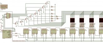
Approximately all energy-saving lamps are made according to this scheme:
In order to make a switching power supply, we will change it to this form:
First, we remove all the pins, two capacitors and diodes (if any), as you can see in the photo, I didn’t have them.
We remove the pulse inductor, there are two options, the first is that the secondary winding is wound into the free space of the inductor and it is installed back on the board. In this case, it will not be possible to obtain more power. The second method is to wind a pulse transformer, for example, on a ferrite ring. When installing radiators on transistors, you can get a power of 100W or more.
I didn’t need a lot of power, the goal was to power a meter of white LED strip to make something like a kitchen night light :). I also chose about 8-10 Volts for the supply voltage, so that the tape would not glow very brightly; in this mode of operation it would last much longer.
Popular articles Dahlia from foamiran
The throttle is removed, we disassemble it, this is quite easy to do, unwind the yellow synthetic film, and take out the two halves of the ferrite. Before winding the secondary winding, you need to make insulation, simply wrap electrical cardboard, plain paper, or plumbing tape around the primary winding. Next we wind a few turns.
We also make insulation and bring out the edges of the winding.
We assemble the transformer in the reverse order; I used “Second” type glue.
We install the transformer on the board. We connect P1 and P4 with a jumper (see the diagram).
For testing, I connected the rest of the coil of LED strip, having first rectified the voltage using a diode and a capacitor. The output voltage was 9 Volts.
The switching power supply from the energy-saving lamp is ready, working, nothing gets hot on the board.
Price overview
When compiling the table, we considered retail prices for the relatively inexpensive Weller 8100 UC soldering iron; the cost of models from unknown Chinese manufacturers was not taken into account, as was the delivery price.
| City | Cost, USD | City | Cost, USD |
| Dnepropetrovsk | from 24.8 | St. Petersburg | from 24 |
| Donetsk | from 24.8 | Minsk | from 26 |
| Krasnodar | from 25.4 | Moscow | from 24 |
As can be seen from the table, the price of this electric pulse soldering iron in different cities of Russia and the CIS countries does not vary much; this result is explained by the large number of stores selling online.
How to make an LED lamp
Necessary materials
In order to convert an energy-saving light bulb into an LED light bulb with your own hands, you need to have the following list of materials with you:
- A burnt out, broken lamp.
- A small piece of fiberglass for connecting parts together. If you have other ideas (besides soldering), you can use yours to solve the question of how to attach the LEDs.
- A set of radio elements corresponding to a specific circuit, including LEDs. Experts advise choosing ordinary parts for assembling an LED light bulb with your own hands, which are presented in a large assortment on every radio market, where their cost is significantly lower.
- A capacitor with a volume of 0.022 Mf, the voltage in which is 400 V, one resistance is designed for 1 mOhm and a pair of resistances for 200 Ohms.
- LEDs are cheaper to solder in the required quantity using a strip.
Making a circuit
The process of creating a circuit with your own hands begins with cutting out a circle with a diameter of 30 mm from PCB. Next, apply paths on the circle; nail polish does a good job of this. After covering one coat, set the piece aside until it is completely dry.
Element connection diagram
At this time, you can do chemistry, namely, make a mass with your own hands that dissolves copper. To do this, mix copper sulfate and ordinary kitchen salt in a ratio of 1:2. Be sure to add a small amount of warm water (but not hot!) and dip the future board into the resulting mixture. Within a day, you will notice how the copper has disappeared from the textolite circle, only the part that was treated with varnish remains.
At the final stage, soldering is performed. However, before moving on to this phase, use a special solvent and get rid of the varnish layer. Then tread the existing paths.
LED lamp circuit
Take a millimeter drill and make holes in the areas where the elements are fixed. Finally, move on to full soldering of the circuit. If you are not new to working with a soldering iron and have certain skills, to create a 220 V LED light bulb with your own hands, or rather, its driver board, you just need to set aside 30 free minutes.
The assembly process is not complete without disassembling the old energy-saving lamp. Use a metal saw to cut the perimeter at the very end of the plastic. Take out all the internal parts, leaving only the wires coming from the base of the old lamp. Arm yourself with a soldering iron again and fix the board to these wires.
Attach the circuit equipped with LEDs to the inner surface of the plastic. Before final gluing, turn on the lamp; if it works, use hot glue.
How to do without soldering
Some people may not be comfortable with soldering; in this case, as an alternative, the driver for the product is replaced with a full-fledged power supply designed for fixing and operating the LED strip. It is due to the use of a whole piece of tape, and not its individual sections, that soldering and global rework are not required.
What problems might arise? With the dimensions of the power supply. Here you will either need to redo the electrical wiring from A to Z (the lighting of the building is reduced to one branch), or power each lamp or row of products with a different transformer. If the house is equipped with spotlights, you can select the very first one from the circuit and place a power supply in front of it, after which, instead of 220 V lamps, install homemade 12 V LED models.
How to assemble light bulbs
Do-it-yourself lighting products are assembled from plastic pipes cut into separate sections. An LED strip is attached to the sides of the pipes using a soldering iron; be sure to check the parallel circuit. At the end of the bundle of wires, place two pins that act as a base.
If the lamps are equipped with a traditional socket for fixing the lamp, the process is simplified significantly - it is enough to modernize old energy-saving devices, and there is no longer any need to use internal boards. As before, the sample is disassembled, and all the “internals”, except the base wires, are removed. The cap from which the fluorescent tubes came out is closed with a cylinder made of plastic, on which sections of the LED strip are fixed. These tapes are connected to the wires from the base.
https://youtube.com/watch?v=ISalGPhtjtQ
When connecting, take into account the “+” and “-”. Plus, it is advisable to solder to the lower component of the base. If the connection does not produce results, you can solve the problem by reconnecting the power supply output to the wires.
Types of soldering irons
A heated tool that connects metal parts with special solder made from alloys based on lead, tin or copper is called a soldering iron. The parts that make up the soldering iron are simple and few in number:
- Electrical power cord with plug.
- Lever.
- A casing that protects the inside of the instrument.
- A heating element.
- Kernel.
- Tip, or sting.
To achieve maximum connection, copper is used to make the tip and rod.
One of the most common tools is a soldering iron with a nichrome spiral heater. Some models have a thermocouple sensor that turns off the tool when operating temperature is reached.
More modern are devices with a heater in the form of ceramic rods. They heat up faster, have greater ability to configure the necessary parameters and have a long service life.
A device with a ferromagnetic coating tip is heated by induced magnetic field currents. This device is called an induction soldering iron. The flame from gas combustion heats the tip in a gas soldering iron through a special nozzle. This device is autonomous, and refilling is possible from a regular gas cartridge.
Low-power, battery-powered soldering irons are also mobile and are used for repairing small parts. Ultrasonic tools are used for flux-free soldering using lead-free solders.
How to make a power supply from an energy-saving lamp
It may seem that this is the work of so-called radio amateurs, experienced professionals working with circuits and electrical appliances.
But in reality, it turns out that almost anyone who comes across electrical devices in everyday life can “revive” old equipment. It is enough to work according to the plan and have a diagram of the device in front of your eyes. We have prepared a visual electrical diagram and a step-by-step plan for working on the ESL block.
Disassembling the lamp
Be careful when disassembling the ESL. By damaging the integrity of the flask, you can release harmful mercury vapors that quickly spread around. We recommend that you carefully, slowly pry at the seam with a small screwdriver.
When you have discovered a circuit connected to the flask with four power leads, cut them off and carefully examine the condition of the elements. Outwardly, you can understand that they are out of order, by burnt places, swelling; The ends of the connections may become unsoldered. After an external inspection, it is necessary to ring the electrical circuit. According to the experience of radio amateurs, capacitors and resistors often deteriorate in ESL.
Popular articles Collar necklace
Spare elements are taken from the circuits of other energy-saving lamps that you have set aside for the future power supply. After you have assembled one from several schemes, you can move on.
You need to decide what power supply you would like to build. If the power of the unit is equal to the power of an energy-saving light bulb, then no major changes will be required; if you want to increase the power of the power supply, you need to add a secondary winding lined with a copper conductor.
Preparatory work
So, we have already removed the contacts going to the flask. The red one in the diagram shows the ESL node we removed. We install a jumper on the remaining ends in the circuit. To increase the output power, you need to add an additional (secondary) winding to the inductor (in diagram L5). There will be a power reserve in the power supply due to it.
In addition, we add new details to the diagram:
- capacitors (in the diagram C9, C10)
- diode bridge (VD14-VD17)
The required number of turns for the secondary winding is determined in several stages:
- A temporary winding of about ten turns is laid and connected to a load resistance having characteristics of 30 watts or more, and the resistance itself is from 5 to 6 ohms;
- After connecting the power, the voltage across the load resistance is measured;
- The resulting voltage figures are divided by the number of turns - this is how you find out what voltage comes to one turn;
- Calculation of the required number of turns to power the permanent winding and selection of the conductor diameter for the secondary winding.
We recommend choosing a secondary winding diameter of 0.5 mm.
Number of turns needed:
X = Uout (achievable power supply voltage) / Uvit (voltage of one turn)
Drastic changes
However, it is safer to make a switching power supply from scratch by looking for a transformer with the required characteristics in old electronics. Factory transformers will be much more durable than homemade ones. And you don’t need to calculate the number of turns using the formula; just connect the ends of the transformer winding to the circuit with a soldering iron.
If you want to greatly increase the power of the power supply, several times, then you need to unsolder the old inductor and connect a new one (in the diagram below it is designated as TV2). We connect two diodes that make up the output rectifier to the block (on the VD14, VD15 diagram), replace the diodes on the input rectifier with higher power (on the RO diagram) and install a capacitor with a larger capacitance (on the CO diagram). It is necessary to select a capacitor in the proportions 1 Watt of output power = 1 microfarad. The diagram shows one hundred microfarads per one hundred watts.
You can test the power supply on a light bulb of similar power. The main thing is to ensure that the temperature of the transformer in our unit does not exceed 60ºС, and that of the transistors does not exceed 80ºС. Temperature is measured with mercury or alcohol thermometers. There are also so-called factory thermocouples and thermal resistances. An experienced radio amateur always has such devices at hand.
We recommend watching the video instructions:
Expanding opportunities
If you need a more powerful power supply, this circuit may again be useful to you. However, in order to achieve the required power, some design changes cannot be avoided. So you will need to supplement the lamp block with a distribution transformer and a pair of rectifiers. Many radio amateurs know that finding a suitable transformer is not an easy task. In this case, you can select a suitable component by disassembling old computers or TVs. You can, of course, try to wind a pulse transformer with your own hands. To do this, you need to wind a certain number of turns of thick copper wire onto a base made of a ferrite magnetic core in the form of a ring. From experience, to get 50 W charging you need to take a ring with a diameter of about 28 mm. For the specified power, a wire with a diameter of 0.35 mm is ideal. The main difficulty is to select the number of turns in the transformer. This can be done experimentally - alternately performing winding and testing indicators, achieving the desired results in terms of power. Also, to simplify calculations, there are a lot of software tools, each with its own advantages and disadvantages. Here it is more convenient for someone. For our example, the calculated standard is 108 turns, but in fact a little more than 110 fits. Place the turns evenly throughout the entire ring to get maximum power. Don't forget to make a gasket between the ferrite ring and the wire to eliminate the possibility of breakdown.
Turns in a transformer
This work is monotonous, painstaking and lengthy, and not everyone wants to spend an evening winding. So it’s better to stock up on the necessary serial production components in advance. The photo below shows ready-made transformers, in comparison with a homemade “donut”. There is no need to talk about the reliability and strength limits of models produced in a factory. Therefore, if possible, use them, especially if you are charging complex electrical appliances.
Transformers
The resulting transformer must be connected to a board obtained from a light bulb. One of the connection options is shown in the diagram below.
Detailed UPS diagram
Additionally, you will have to install a pair of pulse diodes (VD14 and VD15). It would be a good idea to install diodes VD1-VD4 of higher power on the input bridge rectifier. It is also advisable to rewind the input choke with a wire of larger diameter (in the diagram it is indicated as L0). If the transistor produces insufficient current amplification, replace resistors R5 and R6 with models with a lower rated resistance. It may also be necessary to increase the power of the resistors in the emitter and base circuits. We recommend measuring currents, voltages, frequencies and temperatures at all stages of assembly. As problems with a particular node are identified, appropriate additions must be made to ensure uninterrupted operation of the circuit. There are no universal recipes, since the pragmatic Chinese, in order to save money, often replace expensive radio components with cheap analogues, and no matter how hard you try, the assembly does not work. So this method of using lamp contents is more suitable for more advanced radio amateurs.
Of course, if you are a beginner and cannot accurately calculate everything: the number of turns in an inductor or transformer, and prevent possible voltage surges, we do not recommend using such homemade power supplies made from lamps to charge devices with “thin” complex electronics, such as smartphones. Due to voltage surges or inappropriate frequency, they can quickly become unusable. Such a pulsed source is more suitable for use in conjunction with LED strips or fluorescent lamps that do not have a control unit, or with simple electrical appliances. It can also serve as a source of energy for any of your other radio-electronic homemade products. Even if the first connection experience is unsuccessful, it will not be so excruciatingly painful and offensive. It's better to start with the simplest options. Try it, but don’t forget - safety comes first in this matter!
Repair for burnt thread
Repair work with the thread entails the work of the ballast in emergency mode. This means that if a serious overload occurs, the ballast will fail. In the absence of overloads, the lamp usually continues to function uninterruptedly for 9–18 months. The service life depends on the parts used in the circuit, as well as their quality.
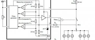
If only one thread burns out, we shunt it with a resistance. How to do this is shown in the figure.
To create a shunt resistance (RSh), it is recommended to install a resistor whose resistance is equal to the second (undamaged) filament. However, this approach is not completely reliable, since we measured the resistance of the “cold” thread. If you install an equivalent resistor, there is a risk that it will soon burn out. Therefore, it is better to install a resistor with a nominal resistance of 22 Ohms and a power of 1 W or more.
Trial
A test run should be carried out with certain precautions taken so as not to damage the power supply:
- The first test run should be carried out using a 100 W incandescent lamp to limit the current to the power supply.
- Be sure to connect a 3-4 Ohm load resistor with a power of 50-60 W to the output.
- If everything went as expected, let it run for 5-10 minutes, turn it off and check the degree of heating of the transformer, transistors and rectifier diodes.
If no errors were made during the process of replacing parts, the power supply should work without problems.
If a trial run shows the unit is working, all that remains is to test it in full load mode. To do this, reduce the resistance of the load resistor to 1.2-2 Ohms and connect it directly to the network without a light bulb for 1-2 minutes. Then turn off and check the temperature of the transistors: if it exceeds 60 0 C, then they will have to be installed on radiators.
As a radiator, you can use either a factory radiator, which will be the most correct solution, or an aluminum plate with a thickness of at least 4 mm and an area of 30 sq. cm. It is necessary to place a mica gasket under the transistors; they must be secured to the radiator using screws with insulating bushings and washers.
Operating principles and devices
Fluorescent lamps are a hollow glass bulb filled with mercury vapor. At the moment of switching on, an electric arc discharge is created between two electrodes, arranged by a starting capacitor. It produces ultraviolet radiation that is invisible to the human eye. To convert it into visible light, a phosphor is applied to the walls of the flask (the compounds most often used are calcium halophosphate or calcium-zinc orthophosphate). When ultraviolet light passes through the phosphor, a bright light is produced. Its light output significantly exceeds the glow of tungsten in incandescent lamps with similar energy consumption. The color depends on the composition of the phosphor.
Unlike a conventional lamp, energy-saving fluorescent models cannot be connected directly to a 220 V current source. When turned off, the mercury vapor inside the bulb has a very high resistance, so a high voltage pulse must be applied to form a discharge. In addition, at the moment of startup, immediately after the discharge occurs, the lamp has a large negative resistance, which, without protective elements in the circuit, can lead to a short circuit. For tubular options, an electromagnetic ballast is used, which is installed in the lamp itself.
The Edge of Mastery
If you have a pulse soldering iron circuit, it’s not difficult to make it yourself. This tool is turned on and off using a button located on its body. For the convenience of working with a soldering iron, a low-power light bulb is mounted in it. Its tip is made of copper wire, the thickness of which will be 1 mm. The time it takes for the tool to warm up and the temperature of the tip will depend on the cross-section. The transformer core must be assembled from iron (W-shaped). For example, Sh-26, Sh-20. Next, the primary winding is made with SED wire 0.22-0.25 in the amount of 1500 turns. The same wire is used to wind the light bulb (25 turns). And then the power winding of the core is made of copper wire, making 5-6 turns. The copper wire must have a cross-section of 25x0.3 mm. The core is tightened from above with studs and nuts. They must be insulated with fiberglass and textolite washers. Conductive busbars are similarly insulated.
Making a UPS with your own hands
Most often, during the manufacture of a switching power supply, it is necessary to slightly change the structure of the inductor if a two-transistor circuit is used for this purpose. Of course, some elements in the device will need to be removed.
If a power supply is being manufactured that will have a power of 3.7-20 Watts, then the transformer is not the main component. Instead, it is best to make several turns of wire, which are attached to the magnetic circuit. To do this, it is not necessary to get rid of the old winding; they can be done on top.
It is recommended for this purpose to use MGTF brand wire with fluoroplastic insulation. A small amount will be needed. Despite this, the winding will be completely covered, since most of it is allocated to insulation. Because of this, such devices have low power ratings. To increase it, you need to use an AC transformer.
Using a transformer
The main advantage of making a power supply with your own hands is that it is possible to adapt to the performance of the transformer. In addition, there is no need for a feedback circuit, which is most often an integral part in the operation of the device. Even if some mistakes were made during assembly, most often such a block will work.
Popular articles How to cut snowflakes from paper: more than 140 templates, step-by-step diagrams
In order to make a transformer with your own hands, you will need to have a choke, inter-winding insulation, and a winding. The latter is best made from varnished copper wire. It should be remembered that the choke will operate under voltage.
The winding must be carefully insulated even when it has a factory-made special protective film made of synthetic material. As insulation, you can use either electrical cardboard or ordinary paper tape, the thickness of which should be at least 0.1 mm. Only after the insulation has been made can copper wire be wound over it.
As for the winding, it is best to choose the wire as thick as possible, but the number of required turns can be selected based on the required performance indicators of the future device.
Thus, it is possible to make a UPS that will have a power of more than 20 W.
Purpose of the rectifier
To prevent saturation of the magnetic circuit in the pulse unit, it is necessary to use only a full-wave output rectifier. In the event that the transformer must step down the voltage, it is recommended to use a zero-point circuit. To implement such a circuit, you need to have two absolutely identical secondary windings. You can make them yourself.
It should be taken into account that a diode bridge type rectifier is not suitable for this purpose. This is due to the fact that a significant amount of power will be lost during transmission, and the electrical voltage value will be minimal (less than 12V). But if you make a rectifier from special pulse diodes, then the cost of such a device will be much more expensive.
Setting up the device
After the power supply is assembled, you need to check its operation at maximum power. This is necessary in order to measure the heating temperature of the transformer and transistor, the values of which should not exceed 65 and 40 degrees, respectively. To avoid overheating of these elements, it is enough to increase the cross-section of the winding wire. It also often helps to change the power of the magnetic circuit upward (the ESR is taken into account). If the choke was taken from the ballast of an LED lamp, it will not be possible to increase the cross-section. The only option is to control the load on the device.
We calculate the capacity of the required voltage
To save money, capacitors with a small capacity are used. The ripple indicator of the incoming voltage will depend on them. To reduce ripple, it is necessary to increase the volume of capacitors; this is also done to increase the ripple rate only in the reverse order.
To reduce size and improve compactness, it is possible to use electrolyte capacitors.
For example, you can use capacitors that are built into photographic equipment. They have a capacity of 100µF x 350V.
To provide a power supply with an indicator of twenty watts, it is enough to use a standard circuit from energy-saving lamps and without winding additional winding on the transformers. In the case where the choke has free space and can accommodate additional turns, you can add them.
Thus, you should add two to three dozen turns of the winding to be able to recharge small devices or use the UPS as an amplifier for equipment.
20 watt power supply circuit
If you need a more effective increase in power rating, you can use the simplest copper wire coated with varnish. It is specially designed for winding. Make sure the insulation on the standard inductor winding is good enough, as this part will be affected by the incoming current. You should also protect it from secondary turns using paper insulation.
The current power supply model is 20 watts.
For insulation we use special cardboard with a thickness of 0.05 millimeters or 0.1 millimeters. In the first case, two words are needed, in the second, one is enough. We use the maximum cross-section of the winding wire; the number of turns will be selected by trial. Usually quite few turns are needed.
Reducing the transverse diameter of the wire used will of course increase the number of turns, but this will only have a negative effect on the power.
To be able to increase the power of the power supply to hundreds of watts, it is necessary to additionally tighten the pulse transformer and expand the capacity of the filter capacitor to 100 farads.
100 watt power supply circuit
To lighten the load and reduce the temperature of the transistors, radiators should be added to them for cooling. With this design, the efficiency will be around ninety percent.
Transistor 13003 should be connected
A transistor 13003 should be connected to the electronic ballast of the power supply unit, which can be secured using a shaped spring. They are advantageous in that there is no need to install a gasket with them due to the absence of metal platforms. Of course, their heat transfer is much worse.
It is best to carry out fastenings using M2.5 screws, with pre-installed insulation. It is also possible to use thermal paste that does not transmit mains voltage.
Connection to a 220 volt network
The connection is made using an incandescent lamp. It will serve as a protective mechanism and is connected in front of the power supply.
In this case, the lamp serves as a ballast, which has a non-linear indicator and perfectly protects the UPS from network malfunctions. The lamp power value must be selected in the same way as the power of the switching power supply itself.
In this article you will find a detailed description of the process of manufacturing switching power supplies of different powers based on the electronic ballast of a compact fluorescent lamp.
You can make a switching power supply for 5...20 Watts in less than an hour. It will take several hours to make a 100-watt power supply. https://site/
Assembling a simple light bulb from LEDs
Before you decide to assemble an LED lamp with your own hands, you need to carefully consider where and how such a circuit will be attached and placed. Let's consider what basic materials are needed for this, what housing options can be used for them, and what the step-by-step process of assembling a homemade lamp looks like.
Materials for production
To make an LED lamp with the specified characteristics with your own hands, you will need the following materials:
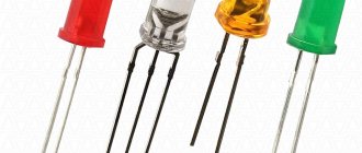
- LEDs. These can be either individual elements, for example, NK6 with a current of 100 mA and a voltage drop of 3 V, or ready-made ice strips.
- Rectifier diodes or bridges, for example, 1N4007.
- Fuse (can be removed from the base of the used lamp).
- A capacitor with a capacity and voltage equal to the led crystals in the assembled chain.
- Base for mounting LEDs. It can be a plastic or cardboard structure with good electrical insulating and fireproof properties.
- Adhesive for mounting diodes to the frame.
Housings for LED devices
For maximum ease and speed of assembly of the LED circuit, you can use the following housing options:
- Socket.
- Fluorescent lamp housing.
- Halogen bulb.
- Specially made frame.
Using the first method involves removing the bulb and spiral, and then placing diode elements inside the circuit and outside on the board. The assembled structure can be screwed into any socket, but the aesthetics of such a lamp will not be up to par. Therefore, it is more suitable for closed lampshades.
The second method is more convenient and practical. In this case, the flask must first be dismantled and the board removed from the base. The following assembly options are then possible:
- Ice crystals are inserted into pre-drilled holes in the lid placed under the bulb, and the components are installed in the base.
- The board with LEDs is placed inside the base, while the LED elements are mounted in a lid made from a plastic bottle or a suitable sized plastic mug.
Both options have an aesthetic appearance and make it possible to use such an LED lamp in an open chandelier. The use of halogen lamps for this purpose is very limited - due to the impossibility of then screwing them into a standard cartridge. This method is applicable for making indicators and special devices with your own hands.
Step-by-step instruction
Let's look at how to make a simple LED lamp with your own hands based on an E27 fluorescent base. To begin, you need to prepare the following materials:
- E27 modification socket from a burnt-out old energy-saving lamp.
- RLD2-1 driver.
- NK6 diodes.
- A piece of thick cardboard, better than plastic.
- Instant glue.
- Wires.
- Scissors, soldering station, flat screwdriver, pliers and other related tools.
The instructions for assembling a basic LED lamp with your own hands look like this:
- An old fluorescent lamp is being disassembled. For this purpose, there are recesses with latches on the base. You just need to pry them off with a screwdriver, and the tube with the board will be disconnected.
- Next, you need to dismantle the light-emitting tubes and remove the round plate with six holes.
- A cardboard or plastic base of similar diameter is attached to the plastic to securely attach the LEDs.
- Two holes are pierced in the base for each of the six mounted diodes. If cardboard is used, then the latter need to be glued, and if plastic is used, simply press the ice elements using the electrodes.
- To each pair of 3 0.5 W LEDs, one RLD2-1 driver is connected in parallel in accordance with the following diagram.
- Solder the input contacts of the drivers to the terminals of the base and install them inside.
- In this case, be sure to put another cardboard or plastic spacer between them and the board for electrical insulation.
- Insert the base with diodes into the base.
- Connect to the network and check the operation of the LED lamp.
An ice lamp assembled with your own hands according to this scheme will consume only 3 watts and produce a luminosity of about 120 lm. It can be screwed into any suitable electric cartridge.
Without dismantling
The easiest way is without dismantling, but you will have to buy a couple of Wago clamps. In general, bite out all the wires suitable for the cartridge at a distance of 10-15mm or more. Next, insert them into the same Vago clamp.
Do the same with the other side of the lamp. If the wago terminal block does not have enough contacts, you will have to use 2 pieces.
After this, all that remains is to feed a phase into the clamp on one side and zero on the other.
No Vago, just twist the wires under the PPE cap. With this method, you do not need to deal with the existing circuit, jumpers, get into the cartridge contacts, etc.
Additional details
It is necessary to attach a handle, for example, a wooden one, to the assembled transformer, the main thing is that the material from which it is made is a dielectric. We must not forget about the button with which the soldering iron will turn on and off. Moreover, heating should occur only when the button is pressed. This is very convenient, as it saves energy and prevents the soldering iron from overheating. A copper wire tip is also made and attached. It is best if its diameter is 1-3 mm.
The process of converting a step-down transformer
When choosing a step-down transformer, you should remember that its power should be from 50 to 150 watts. A smaller one will lead to overheating and failure of the device, a larger one will lead to unnecessary weight and bulkiness.
Transformer-based pulse soldering iron
The primary winding does not need to be redone, but the secondary winding should be removed by disassembling the plates. An exact calculation of the secondary winding is not required; it is more important to ensure the maximum cross-section of its wire or bus. Typically, two to six turns are wound. The cross-section should be in the range from 6 to 10 mm2.
Important! The turns of the secondary winding should not touch each other and the transformer core.
If the secondary winding is made of a copper busbar, its ends can be left longer and used as current conductors by attaching the tip directly to them. The absence of unnecessary connections will increase the reliability of operation and improve the temperature regime of the device.