DIY ESR meter. There is a wide range of equipment breakdowns, the cause of which is precisely the electrolytic capacitor. The main factor in the malfunction of electrolytic capacitors is “drying out,” familiar to all radio amateurs, which occurs due to poor sealing of the housing. In this case, its capacitive or, in other words, reactance increases as a result of a decrease in its nominal capacity.
In addition, during operation, electrochemical reactions take place in it, which corrode the connection points between the leads and the plates. The contact deteriorates, eventually forming “contact resistance”, sometimes reaching several tens of ohms. This is exactly the same if a resistor is connected in series to a working capacitor, and moreover, this resistor is placed inside it. This resistance is also called “equivalent series resistance” or ESR.
The existence of series resistance negatively affects the operation of electronic devices by distorting the operation of capacitors in the circuit. Increased ESR (about 3...5 Ohms) has an extremely strong impact on the performance of switching power supplies, leading to the burning of expensive microcircuits and transistors.
The table below shows the average ESR values (in milliohms) for new capacitors of various capacities depending on the voltage for which they are designed.
It is no secret that reactance decreases with increasing frequency. For example, at a frequency of 100 kHz and a capacitance of 10 μF, the capacitive component will be no more than 0.2 Ohm. When measuring the drop in alternating voltage having a frequency of 100 kHz and higher, we can assume that with an error in the region of 10...20%, the result of the measurement will be the active resistance of the capacitor. Therefore, it is not at all difficult to assemble an ESR meter for capacitors with your own hands .
Description of ESR meter for capacitors
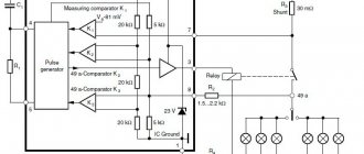
The pulse generator with a frequency of 120 kHz is assembled using logic elements DD1.1 and DD1.2. The generator frequency is determined by the RC circuit on elements R1 and C1.
For coordination, element DD1.3 was introduced. To increase the power of pulses from the generator, elements DD1.4...DD1.6 were introduced into the circuit. Next, the signal passes through the voltage divider across resistors R2 and R3 and goes to the capacitor Cx under study. The alternating voltage measurement unit contains diodes VD1 and VD2 and a multimeter as a voltage meter, for example, M838. The multimeter must be switched to DC voltage measurement mode. The ESR meter is adjusted by changing the R2 value.
The DD1 - K561LN2 microcircuit can be replaced with K1561LN2. Diodes VD1 and VD2 are germanium, it is possible to use D9, GD507, D18.
The radio components of the ESR meter are located on a printed circuit board, which you can make yourself. Structurally, the device is made in the same housing with the battery. Probe X1 is made in the form of an awl and attached to the body of the device, probe X2 is a wire no more than 10 cm in length with a needle at the end. Capacitors can be checked directly on the board; there is no need to unsolder them, which makes it much easier to find a faulty capacitor during repairs.
Contact models
Contact wood moisture meters are well suited for working with plywood and parquet. Additionally, in the construction industry, devices are used to determine the humidity of panels. If we talk about contractual features, then low-frequency generators are used in the devices. The probes themselves are installed in a tubular type.
The dielectric constant of most moisture meters does not exceed 3 F/m. Models of this type can keep the maximum temperature at 40 degrees. The display is used in both line and text types. Many modifications are equipped with temperature sensors. Many devices have a calibration function. On average, a high-quality moisture meter costs around 2 thousand rubles.
Device setup
After completing installation and testing, you need to check the frequency on probes X1 and X2 with an oscilloscope. It should be within 120...180 kHz. If this is not the case, then by selecting resistor R1 the desired frequency is achieved. Next, you need to prepare a set of resistors of the following ratings:
1, 5, 10, 15, 25, 30, 40, 60, 70 and 80 ohms.
It is necessary to connect a 1 Ohm resistor to the probes X1 and X2 and rotate R2 until the multimeter reads 1 mV. Then, instead of 1 Ohm, connect the next resistor (5 Ohms) and, without changing R2, record the multimeter reading. Do the same with the remaining resistances. The result is a table of values from which the reactance can be determined.
Source: www.joyta.ru
Model EMCO AR
In the construction industry, the presented moisture meter is in great demand. It is ideal for working with parquet and panels. This moisture meter is also equipped with a thermometer. Another advantage of the modification can be safely called the presence of needle-type contacts. The manufacturer provides a three-channel microcircuit for the model, so wood moisture is measured quickly. The electrodes are of the capacitive type.
The maximum humidity threshold does not exceed 40%. In terms of size, this moisture meter is very compact and belongs to the class of portable devices. According to the documentation, its weight without batteries is 80 g. The resolution of the model is at the level of 1.3 pH. The maximum permissible temperature of the model is exactly 35 degrees. The presented device must not be used in cold weather. The measurement accuracy fluctuates around 1.4%. In stores, this device can be found for 2100 rubles.
How to make an ESR meter with your own hands
Most often, if modern electronic equipment fails, electrolytic capacitors are to blame. Additional difficulties in finding broken capacitors arise from the fact that it is difficult to measure their capacitance, since the capacitance value in a defective capacitor may be almost the same as the nominal value, but the ESR will be high. Therefore, in this material we will discuss how to make an ESR meter with your own hands.
Most often, precisely because of the high ESR value, the correct operation of radio equipment cannot be fully realized.
To make it easier to find the faulty part, we will manufacture a simple analog ESR meter. The device works on the following principle: the resistance value in the capacitor is checked when the frequency value = 100 kHz. Capacitors whose capacitance exceeds several microfarads will have a value approximately equal to the ESR.
There is an opinion that an ESR meter does not need very high accuracy; in practice, it has been verified that the ESR in a faulty capacitor is several times greater than in a working element.
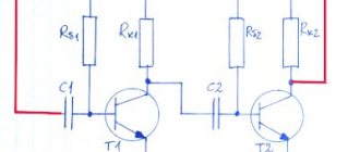
The device manufacturing process begins by simulating the circuit in LTspice. You can see the names of the main functional units in the diagram.
The result of the simulation is this diagram, which shows how far the needle in the microammeter will deviate, taking into account the ESR indicators.
Using the LTspice schematic results as a basis, you can build a schematic diagram in OrCAD. The device is powered using a 9 V supply, and to stabilize the voltage we use the LM7805 microcircuit. In addition, in order to make an ESR meter with your own hands, you will have to use transistors 2N3904 (npn) and 2N3906 (pnp), however, normal operation of the circuit will be ensured using any common transistors. When choosing diodes, we will focus on 1N5711. The measuring head current is 50 µA.
The maximum voltage value at the contacts of the measured capacitor is no more than 100 mV, which makes it possible to use the device for in-circuit (without soldering the capacitor) testing.
Here you can see the appearance of the board layout, it is one sided and has no jumpers. We try to use SMD elements, although some mounting holes will still be needed.
Is there an alternative to an electronic incubator humidity meter?
Despite the fact that a ready-made device for measuring humidity is not that expensive, some poultry farmers recommend making a device designed for the same purpose yourself. They explain this by the fact that the devices used for a homemade hygrometer give more accurate readings than their electronic counterparts.
How to make a homemade device:
- To do this, you will need two ordinary mercury thermometers, which measure air temperature, a board and water.
- Thermometers are fixed along the edges of the board so that they are parallel to each other, and a container with distilled water is placed under one.
- We wrap the mercury ball in cotton cloth and tie it not very tightly with thread.
- We lower the edges of the fabric into the water by about 5 millimeters.
- The indicators recorded by thermometers are compared with each other and compared with specially designed tabular data, which are given in the description of psychrometers. For example, if the dry bulb reading is 37.5 degrees and the wet bulb reading is 26 degrees, then the relative humidity in the chick hatcher is 38%. Thus, the air humidity in the incubator is calculated.
Thus, the success of the chick hatching process is influenced not only by the level of air temperature, but also by its humidity. The latter can be measured with a special device - a hygrometer, which you can buy at any pet store or make yourself. However, the second option is quite labor-intensive.
Special moisture meters are used. Today there are needle, contact and chip modifications. In terms of parameters, they are quite different. However, there are not many manufacturers of moisture meters on the market. The main companies include, first of all, EMCO and Valcom. On average, a good moisture meter on the market costs around 1,500 rubles.
ATTACHMENT FOR MULTIMETER ESR METER
I not only learned from others that such a meter is necessary for a radio amateur, but also felt it myself when I undertook to repair an old amplifier - here you need to reliably check each electrolyte on the board and find the one that has become unusable or replace them 100%. Selected check. And I almost bought an advertised device called “ESR – mikro” via the Internet. What stopped me was the fact that they praised him too much - “over the edge.” In general, I decided to take independent action. Since I didn’t want to try microcontroller devices, I chose the simplest, if not primitive, circuit, but with a very good (thorough) description. I delved into the information and, having some inclination towards drawing, began to design my own version of the printed circuit board. To fit into the case of a thick felt-tip pen. It didn’t work out - not all the details were included in the planned scope. I thought better of it, drew a signet in the image and likeness of the author’s, etched it and assembled it. I managed to assemble it. Everything turned out very thoughtfully and neatly.
But the probe didn’t want to work, no matter how much I fought with it. But I didn’t want to retreat. For a better understanding of the diagram, I redrew it in my own way. And so “dear” (in two weeks of ordeal), it became more understandable visually.
Types of barometers
Barometers with liquid, chemical compounds as a sensitive substance. We will not consider the mercury variety, since the substance is extremely dangerous, and also difficult to obtain. In homemade products, colored plain or distilled water is used. The devices are based on the “E. Toricelli principle”: the liquid descends/lowers in a tube inserted with the open end into a container with the same substance, responding to changes in atmospheric pressure.
Mechanical, they are also aneroids. From a flexible (often corrugated) thin-walled box, bellows - an aneroid capsule made of copper-beryl and similar alloys. This unit is placed inside a sealed housing where a vacuum is created, and it is so sensitive that pressure fluctuations outside it expand or contract it, moving the pusher with an arrow on the scale.
Electronic (digital). It is based on temperature-compensated strain gauge sensors. Similar detectors are installed in electric scales. The operation of the elements is based on the piezoresistive properties of a microscopic strip of silicon that functions as a strain gauge, that is, it is capable of responding to the slightest vibrations, tensions, and surface forces.
The controller (chip) provides the possibility of various settings, analyzes the sensor signal and displays it in numbers on the display. Typically, such a factory device is equipped with a complex of sensors and functions; it measures not only pressure, but also temperature, humidity, and displays the time and date. Digital barometers have become very common in everyday life; their form factor resembles an electronic watch. These are the most accurate meters; they will show values up to 0.2 mV/kPa and better.
Homemade electronic meters will require a calibrated factory load cell.
ESR meter circuit
And I finished the printed circuit board in a cunning way. It became “double-sided” - on the second side I placed parts that did not fit on the first. To simplify the solution to the difficulty that arose, I placed them in a “canopy”. There's no time for elegance here - you need a sampler.
I etched the printed circuit board and soldered the parts. This time I placed the microcircuit on the socket, adapted a connector to supply power, which can be securely fixed to the board using soldering and the case can then be “hung” on it. But the trimmer resistor, with which the probe worked best, I found only this one - far from miniature.
The reverse side is the fruit of pragmatism and the pinnacle of asceticism. Something can only be said here about the probes, despite the elementary design, they are quite convenient, and the functionality is generally beyond all praise - they are capable of contact with an electrolytic capacitor of any size.
I placed everything in a makeshift case, the mounting location was the threaded connection of the power connector. Accordingly, the power minus went to the case. That is, it is grounded. Whatever it is, it is protected from interference and interference. The trimmer is not included, but it is always “at hand” and will now be a potentiometer. The plug from the radio broadcast speaker will, once and for all, avoid confusion with the multimeter sockets. Powered from a laboratory power supply, but using a personal wire with a plug from a Christmas tree garland.
And it, this unprepossessing miracle, took over and started working, right away and as it should. And there are no problems with adjustment - corresponding to one ohm, one millivolt is easily set, approximately in the middle position of the regulator.
And 10 Ohms corresponds to 49 mV.
A working capacitor corresponds to approximately 0.1 Ohm.
Faulty capacitor, corresponds to more than 10 ohms. The probe coped with the task; faulty electrolytic capacitors were found on the board of the device being repaired. All details regarding this scheme can be found in the archive. The maximum permissible ESR values for new electrolytic capacitors are shown in the table:
And some time later I wanted to give the console a more presentable look, but the learned postulate “the best is the enemy of the good” did not allow me to touch it - I’ll make another one, more elegant and perfect. Additional information, including a diagram of the original device, is available in the appendix. Babay told about his troubles and joys .
Discuss the article ATTACHMENT TO THE MULTIMETER ESR METER
Source: radioskot.ru
In this article we will assemble an ESR meter. Is this your first time hearing the word “ESR”? Come on, run and read this article!
Why do you need an ESR meter?
So, why do we even need to build an ESR meter? For those who are too lazy to read the article about ESR, let’s remember how it harms us. The fact is that now almost all electronic equipment uses switching power supplies. These switching power supplies run high frequencies and some of these frequencies pass through the electrolytic capacitors. If you read the article on a capacitor in a direct and alternating current circuit, then you probably remember that the capacitor passes high frequencies through itself almost without problems. And the higher the frequency, the fewer problems there are. This is, of course, ideal. In reality, a resistor is “hidden” in each capacitor. How much power will be released through the resistor?
P is power, Watt
I – current strength, Ampere
R – resistance, Ohm
And as you know, the power that is dissipated by the resistor is heat