Prismatic pseudoscope by Charles Wheatstone.
It switched the images presented to each eye to distort depth perception. A pseudoscope
binoculars are an optical instrument that changes the perception of depth. It is used to study human stereoscopic perception. Objects viewed through it appear, for example, inside out: a box on the floor will appear as a box-shaped hole in the floor.
It typically uses sets of optical prisms or periscope-mounted mirrors to swap the views of the left eye and the right eye.
Target
In the 1800s, Charles Wheatstone coined the name from the Greek ψευδίς σκοπειν, “false view.” The device was used to study his theory of stereo vision. [1][2]
Essentially, pseudoscopic is 3D in reverse. That is, in aerial photography, pools look like buildings, and buildings look like pools. In red and green plotters such as Kelsh and Multiplex, this is achieved by flipping the lenses on the 3D glasses. The images will be in reverse order. The right image will be viewed by the left eye, and the left image by the right eye.
What is an ovoscope for and how to use it?
An ovoscope is a device that is used for ovoscopy of bird eggs, in particular poultry, or in simple words for candling eggs before sending them to an incubator or under a brood hen and during the incubation process itself.
The ovoscope consists of a body in which a light source is placed, it can be a regular lamp or a powerful LED; in the body of the device there is a small hole on which, say, a chicken egg is placed. The light source illuminates the internal structure of the egg, which allows you to visually determine whether there are defects in it or not.
Story
Pseudoscopic binocular microscope, design by Father Querubin d'Orléans, 1677.
Before the pseudoscope itself was intentionally created, it existed as a disadvantage in binocular instruments. The first binocular microscope was invented by a Capuchin monk. Cherubin d'Orléans. Because his instrument consisted of two inverting systems, it accidentally produced a pseudoscopic impression of depth, although this was not recognized by microscopists of the time.
Mirror pseudoscope by G. M. Stratton
Subsequently, the instrument was completely abandoned for almost two centuries. Revived in 1852 by Charles Wheatstone, who published his ideas in his article "On Binocular Vision" in Philosophical Transactions
Wheatstone's work stimulated research into binocular vision, and many variations of pseudoscopes were created, the main ones being mirror or prismatic.
In 1853, the American scientist John Leonard Riddell (1807-1865) invented a binocular microscope, which contained everything necessary for a Wheatstone pseudoscope. [3]
Pseudoscope, or what if you switch eyes
If you saw this picture and realized that your life would never be the same again, then you understand what I mean.
Quite a long time ago, more than two and a half years ago, quite by accident I saw this picture on the Internet (on ffffound, I think), and a switch clicked in my head. An irreversible process has been launched. The usual course of everyday events ceased to reassure me with its completeness. Everything that once filled my life with meaning has become just a pale background for a swollen thought that permanently takes away the resources of my brain; secondary garbage in front of the question that at that time became the center of my existence - “How? What is it like to look into such a structure? What will a person see? (I hope no one noticed that there are three questions here). I definitely wanted to build this design and find out the answer to the question. Years passed, I received a second diploma and graduated from the university. The harsh matan, Lobachevsky's geometry and other abstruse things made me less susceptible to such images, my psyche stabilized (I hope). I became acquainted with the books of Oliver Sacks, where amazing stories were told, including about the perception and decoding of visual information by the brain (for example, the story of a guy blind from birth who, thanks to an operation, gained sight in adulthood).
In addition, I learned that, of course, long before me, smart people thought of building similar structures, using them to study the brain’s reaction to optical illusions and even giving them a clever scientific name - a pseudoscope (and also an invertoscope and my next dream -
).
We found all sorts of communities, articles with mathematical calculations, notes with impressions of use, online stores, interest groups and parties of varying degrees of nerdiness, videos without SMS and registration, crushed stone reinforcement cheap Moscow pick up... sorry, I felt like a real SEO.
Finally, the magic of mystery and the unknown was bulldozed away by the discovery of such a resource as Tiniai and the feature of searching by images on Google Images. Using these services, I found out the source of that primary image. As it turned out, long before me the path was trodden by Anatoly Zenkov, a cool designer, as you can judge from his Vimeo channel. We found a video of testing and a flickr gallery with the process of creating a pseudoscope.
It would seem that this is where the story can end, the universe taught me a lesson:
“The laurels of the pioneer are occupied, everything has already been invented before you, the insight that seems great to you is just a moment of a useless bicycle invention, this world is harsh and uncompromising, and there is no place in it for your rotten ideas "
.
But for some reason the hunt was not discouraged. The desire did not die, it was still warm, although it had diminished. The catalyst during the incubation period was a year spent in prisons called the Armed Forces of the Russian Federation, where you do what you are told, from what you find yourself. Screwdriver? Hacksaw? Ha! For a week I had to ask the officers to take me to the store to buy a bolt with my own money; and if self-tapping screws were needed, they were unscrewed in other places, with the hope that nothing would collapse. So the recent acquisition of freedom has certainly contributed to the transition from ideas to actions.
Another motive that launched the creation process was the desire to get rid of the idea, so that it would find a way out, would not pursue and strangle me, would not take me prisoner
, as Oleg Pashchenko wrote about it (illustration below).
Be that as it may, I found myself with free time, and I decided to build my own mirror pseudoscope.
It all started with calculations on paper. Not tensor calculus, of course, but I also had to struggle with trigonometry.
The overall scale of the disaster can be assessed from the photograph:
After this tedious stage, the desire was born to automate the calculation of mirror coordinates. Firstly, there are quite a lot of changeable input parameters (the angle of the mirrors, the distance between the eyes, their viewing angle, etc.). Secondly, I was already planning to show my brainchild to the world and decided to make it easier for those interested to create the structure.
As a result, I quickly created a program on flash (sorry) in which everyone can calculate all the sizes for themselves. The setting option I used was set to default in the program.
I don't think there's a need to explain every slider. I'll just mention the gaps. All calculations were carried out taking into account the “sterile” configuration, i.e. mirrors with zero thickness, everything fits millimeter to millimeter. In life, everything does not work out so smoothly - there is a gap, there is an inconsistency, the curvature of the hands exceeds the permissible norms, etc. Mirrors have a non-zero thickness, which imposes an error: when a beam falls on a reflective surface at an angle other than straight, the effective surface of the mirror is less than the real one, because the beam will not pass through normally from the end of the mirror. This can be seen in the diagram (the fact of refraction of a light ray at the boundary is not shown here):
So I left a centimeter of gap. If anyone is interested in digging around, here are the sources. Written in AS3, but without classes (sorry again) and all this OOP stuff, stupid and simple-minded code.
Well, now that the dimensions have been received, we can begin the big construction project. Finally, I run the dimensions through cinema4d, just to calm down.
Now we return from the paper-virtual world to the real world. We think over the physical implementation of the drawings - materials, fastenings, color. After this, a raid is made on stores - first OBI, then Leroy Merlin.
As a result of glamorous shopping (I very organically wandered around shopping centers with building materials, looking into fashionable shops) we have:
- 4 mirrors with a height of 300 mm and a width of 65, 130, 200 and 265 mm respectively. If you are afraid of awakening the mighty power of handmade mirror cutting in yourself, Leroy Merlin will cut everything, although for good money - 90 rubles. in one cut. As a result, the cutting cost more than the mirrors themselves.
- 4 pieces of 7-layer plywood 1 cm thick (I couldn’t find anything thinner): 300 × 300mm - 2 pcs. (sides), 550 × 300mm - 2 pcs. (up and down). Likewise, in order not to turn your apartment into a sawmill and then find sawdust in the most unexpected places for a couple of years, you can use the free plywood cutting service at OBI.
- Metal corners. I was planning on plastic ones, but OBI didn’t have any of those. Two formats: wide (three meters), for fastening the frame of the box and attaching the back side of the mirrors to the frame; and narrow (two meters), for attaching the reflective side of the mirrors to the frame.
- A hacksaw for metal and a miter box for cutting corners.
- Glue generously for corners. I collected everything - a regular moment, a super moment (in the end I only used it), an epoxy moment. The box itself could, of course, be elegantly placed on the screws, but I really wanted to smell more glue. Damn, did I say that out loud?
- I decided to choose a color scheme similar to Zenkov’s version. For this purpose, black enamel (for the interior) and yellow enamel (for the exterior finishing) with rollers and brushes was purchased. Plus yellow spray paint (not needed) and a black marker for coloring narrow corners, which were only available in white in the store.
After purchasing the materials, I calculated everything in more detail in a vector editor, taking into account the sizes of the corners, the thickness of the plywood and mirrors, so that nothing would overlap. Based on this data, I clarify the coordinates.
We start by lining up the drawings on the top and bottom panels. Here you need to be precise, especially when it comes to matching the top and bottom panels - any mismatch will lead to the tilt of the mirror. At the same time, paint the back sides of the mirrors black.
Based on the refined drawings, we cut corners to connect mirrors to panels and panels to each other.
Before gluing, I paint over the white corners with a black marker. We glue the corners to the mirrors, but do not fix them to the panels yet.
Then we glue everything to the bottom panel according to the markings on it.
We paint all the insides black (after the structure is fully assembled, it will be inconvenient to climb between the mirrors with a brush/roller). At this moment, I decided to abandon the lining of the top panel, relying on the perpendicularity of the corners of the mirror (as it turned out later, in vain).
Install the top cover.
The jamb is immediately detected due to the incorrect order of gluing the corners (more on this at the end) - the upper corner does not fit tightly to the frame. You will have to pick out the corner and glue it separately.
hello
All that's left to do is paint the outside. Seal the cavities with paper.
Cover with black base.
Then two layers of yellow paint. Ready!
The first pancake may not have turned out well, but the implementation is far from ideal (I will describe errors and possible improvements below).
As for the answer to that very question - What is it like?
I will quote Zenkov:
“As it turns out, this device “doesn’t work” for me. Due to poor vision, I had the feeling that I was just looking with one eye. However, after testing the device with other people, many interesting things emerged. For example, it is almost impossible to focus on nearby objects. Distant objects lose volume and become flat. Plus, the understanding of the distance to objects is lost, to the point that some distant objects are literally visible in front of nearby ones. Many compared the effect to 2D games, where the depth of the scene is simulated due to the difference in layer displacement, but noted that it looked like an unfinished game.”
During the work, I made mistakes, mainly due to a lack of patience and engineering experience (*pathosmodoff* well, more precisely, experience in implementing my engineering developments, and I made a model of a gamma radiation detector on GEANT4 at one time *pathosmodoff*), and also because of laziness.
I no longer wanted to think, I wanted to do-do-do until the bitter end, without turning on my brain. Therefore, I planned something wrong, made a mistake somewhere during implementation, changed my mind in the middle of the process, etc. Overall, looking back, what would I have done differently:
- Size. I would still do less. I don’t have an art studio in the attic of an old brick house in the center of Moscow, and there’s not much room for such a thing. Only if you throw it on the closet.
- Panel material. I chose plywood simply on the principle of least resistance (it was in OBI, and I was too lazy to make extra shopping trips). Disadvantages - heaviness, knots, texture (painting is difficult, but it collects dust especially well; visually and to the touch I would like something smooth). The strength of 7-layer plywood is not needed here - in fact, it is only necessary that the structure does not bend under its own weight. If you show persistence and the desire to go shopping, I’m sure you could find a suitable thin, light and durable material from some kind of polycarbonate or something like that.
- Still, I would find the black narrow corners. Of course, I repainted my white ones black with a marker, but this won’t work on the mirror side (the glue dissolves the paint and refuses to sit on the painted side). As was already seen in the diagram above, the reflective surface of the mirror is protected by a layer of glass, because of this, white stripes from the corners are visible in the reflection. It greatly spoils the appearance.
- Another gluing sequence. I would probably first glue the corners to the frame at the top and bottom according to the drawings, and then glue the mirrors to them. The accuracy would be improved. Otherwise, the slightest miscalculation, tilting the mirror, and the effect of the pseudoscope is lost.
- I would read on the Internet about the basics of painting work, so as not to learn everything, so to speak, live. Outside of the story, I left a lot of my fakaps in this area, which I’m even ashamed to remember.
- Crevices. The few holes in the design have no functional benefit. You can either initially lengthen the mirrors to cover them, or, if after assembly, they can be covered with some kind of sheet of black plastic. And it will be visually better, and the effect of the pseudoscope will be stronger, because the eye will not be distracted by extraneous images
Well, a couple of tips:
- It would be a good idea to make sure it works for you first. From Zenkov’s quote above it is clear that not everyone can appreciate the effect of a pseudoscope. If you have vision problems, think about whether you will end up flying.
- Treat mirrors with care. They must be perfectly clean. Any scratch, stain or even a speck of dust breaks the entire effect - the brain understands that they are trying to fool it.
And finally, I apologize for the graphomania, the general atmosphere of posturing and the pouring out of biographical facts that are unnecessary to the reader. I barely stopped myself when I was about to introduce you to my family.
How to make an ovoscope with your own hands and what you need for it.
Let us first consider the diagram of the ovoscope; as can be seen from the figure, the ovoscope consists of several elements:
- Cases.
- Lamps.
- Reflector.
- Cord and plug for socket.
To make the device, we need a housing; for this we can use a medium-sized tin can, for example, a coffee can.
We also need a light bulb, you can take a regular 100-watt incandescent lamp, but an incandescent lamp produces a lot of heat and warms up the body, as an option you can use a 15-watt energy saver.
To connect the lamp you will need a socket for the lamp base, a cord and a plug for the socket.
Let's start manufacturing.
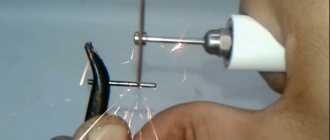
We need to mount a lamp socket in the bottom or side of the jar; to do this, just make a hole with a knife and secure the lamp socket in it, having previously connected a cord with a plug to the socket.
At the bottom of the body, you can make a reflector from a piece of foil to increase the directional flow of light into the opening of the ovoscope.
The hole itself needs to be made in the top cover of the case, the size of the hole should be slightly smaller than the size of a chicken egg, in fact, the egg should not fall into the hole.
If you need an ovoscope, say, for quail eggs, then the hole needs to be made to match the size of the quail eggs.
A similar option with an energy-saving lamp.
That's all, a simple homemade do-it-yourself ovoscope is ready to check eggs.
Using the same principle, you can make an ovoscope from an adapter for a plastic pipe.
As an option, you can make an ovoscope for several eggs at once; to do this, you need to select a suitable housing and install one or more light bulbs into it.
I think this homemade product will be useful if you are incubating poultry eggs both in an incubator and with the help of a hen.
I also recommend watching a video about making a homemade ovoscope.
And also a video on how to ovoscope chicken eggs.
Popular homemade products on our website
- Bake a brick rocket oven in 5 minutes
- Homemade camping stove in 5 minutes
- Smokehouse from a bucket in 5 minutes: photo, video
- The simplest homemade metal detector from...
- DIY Hot Rod
- Do-it-yourself tarabike
- DIY vibration table
- DIY tricycle
- DIY pallet house
- Do-it-yourself gasoline generator
- DIY walk-behind tractor
- DIY concrete mixer
- DIY electric cultivator
- DIY jigsaw
- DIY anvil