Before a detailed consideration of the problem, we will outline the range of tasks; knowing the final goal, it will be easier to choose the right direction. Making speaker systems with your own hands is a rare occurrence. Practiced by professionals and novice musicians when store-bought options are not satisfactory. The problem arises of integrating into furniture or high-quality listening to existing media. These are typical examples that can be solved using a set of generally accepted methods. We'll take a look at it. We do not recommend scrolling diagonally through the speaker system, delve into it!
Acoustic system design
There is no chance of making an acoustic system yourself without understanding the theory. Music lovers should know that the biological species Homo Sapiens hears sound vibrations with frequencies of 16-20,000 Hz through the inner ear. When it comes to classical masterpieces, the variation is high. The lower edge is 40 Hz, the upper edge is 20,000 Hz (20 kHz). The physical meaning of this fact is that not all speakers are capable of reproducing the full spectrum at once. Relatively slow frequencies are better handled by massive subwoofers, and squeaking at the lower edge is reproduced by smaller speakers. Obviously, this means nothing to most people. And even if part of the signal disappears or is not reproduced, no one will notice it.
Speaker system design
We believe that those who set the goal of making their own acoustic system should critically evaluate the sound. It will be useful to know that a suitable speaker has two or more speakers in order to be able to reflect the sound of a wide swath of the audible spectrum. But even in complex systems there is only one subwoofer. This is due to the fact that low frequencies cause the environment to vibrate, even penetrating through walls. It becomes unclear where exactly the bass is coming from. Consequently, there is only one low-frequency speaker – a subwoofer. But as for other things, a person will confidently say from which direction this or that special effect came (the ultrasound beam is blocked by the palm).
In connection with the above, we will divide the acoustic systems:
- Sound in Mono format is unpopular, so we avoid touching on historical excursions.
- Stereo sound is provided by two channels. Both contain low and high frequencies. Equal speakers equipped with a pair of speakers (bass and squeak) are better suited.
- Surround Sound is distinguished by the presence of a larger number of channels, creating a surround sound effect. We avoid getting carried away with subtleties; traditionally, 5 speakers plus a subwoofer convey the range to music lovers. The design is varied. Research is still underway to improve the quality of acoustic transmission. The traditional arrangement is as follows: in the four corners of the room (roughly speaking) there is a speaker, the subwoofer is on the floor to the left or in the center, the front speaker is placed under the TV. The latter is in any case equipped with two or more speakers.
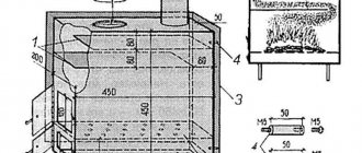
It is important to create the correct enclosure for each speaker. Low frequencies will require a wooden resonator, but for the upper end of the range it doesn’t matter. In the first case, the sides of the box serve as additional emitters. You will find a video demonstrating the overall dimensions corresponding to the wavelengths of low frequencies according to science, practically all that remains is to copy ready-made designs; the topic is devoid of relevant literature.
The range of tasks is outlined, readers understand that a homemade acoustic system is built with the following elements:
- a set of frequency speakers according to the number of channels;
- plywood, veneer, body boards;
- decorative elements, paint, varnish, stain.
Filter order and quality factor
The next parameter that you need to decide on is the order of the filter and its quality factor. This article will consider two orders, first and second.
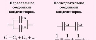
- With the first, everything is simple: there is a coil, there is a capacitor, we calculate their parameters for the required cutoff frequency and, if necessary, adjust the values until the desired frequency response, phase response, and frequency response are obtained.
- The second order is trickier, there are already two coils and two capacitors. A parameter such as the quality factor depends on the values of the nominal values; it determines the steepness of the frequency response decline and, to some extent, the phase shift. Since the influence of the phase shift and slope cannot be speculatively estimated, all that remains is to simply choose which way to think. And think here in the direction of low quality factor, read more inductance in the coils, less capacitance in the capacitors.
How to choose an order. Here we are guided by already familiar considerations about what emitters, especially high-frequency speakers, are capable of. If a big move is contraindicated for him (as in our case), then we give preference to the second order.
To complete the picture, it should be mentioned that the order also determines the degree to which the speakers work together, but this is information for independent reflection.
Acoustics design
Initially, select the number of columns, type, location. Obviously, producing more channels than a home theater has is an unwise tactical move. A cassette recorder will only need two speakers. At least six buildings will be released for the home theater (there will be more speakers). According to the needs, accessories are built into the furniture, the quality of low frequency reproduction is poor. Now the question of choosing speakers: in the publication by Naidenko and Karpov the nomenclature is given:
Three-way speaker system
- Low frequencies - CA21RE (H397) head with an 8-inch fit.
- Mid range - MP14RCY/P (H522) 5" head.
- High frequencies – head 27TDC (H1149) by 27 mm.
They presented the basic principles of designing acoustic systems, proposed an electrical circuit of a filter that cuts the flow into two parts (a list of three subranges is given above), and gave the name of purchased speakers that solve the problem of creating two stereo speakers. We avoid repetition; readers can take the trouble to look through the section and find specific titles.
The next question will be the filter. We believe that National Semiconductor will not be offended if we screenshot the drawing of the Ridico translation amplifier. The figure shows an active filter with a power supply of +15, -15 volts, 5 identical microcircuits (operational amplifiers), the cutoff frequency of the subbands is calculated by the formula shown in the image (duplicated in text):
f = 1/2P RC;
P – number Pi, known to schoolchildren (3.14); R, C – resistor and capacitance values. In the figure, R = 24 kOhm, C is silent.
Active filter powered by electric current
Taking into account the capabilities of the selected speakers, the reader will be able to select a parameter. The characteristics of the speaker's playback band are taken, the overlap junction between them is found, and the cutoff frequency is placed there. Thanks to the formula, we calculate the value of the capacitance. Avoid touching the resistance value, reason: it can (disputed fact) set the operating point of the amplifier, the transmission coefficient. On the frequency response given in the translation, which we omit, the limit is 1 kHz. Let's calculate the capacity of the specified case:
C = 1/2P Rf = 1/2 x 3.14 x 24000 x 1000 = 6.6 pF.
It’s not that big of a capacitance; it’s selected based on the maximum permissible voltage. In a circuit with sources of +15 and -15 V, it is unlikely that the nominal value exceeds the total level (30 volts), take a breakdown voltage (the reference book will help) of at least 50 volts. Do not try to install DC electrolytic capacitors; the circuit has a chance of blowing up. There is no point in looking for the original circuit diagram of the LM833 chip due to Sisyphean labor. Some readers will find a replacement chip that is different... we hope for your understanding.
Regarding the relatively small capacitance of the capacitors (retail and total), the description of the filter says: due to the low impedance of the heads without active components, the ratings would have to be increased. Naturally causing the appearance of distortions due to the presence of electrolytic capacitors and coils with a ferromagnetic core. Feel free to move the range division boundary, the total throughput remains the same.
Passive speaker filters
Passive filters will be assembled with your own hands by anyone trained in soldering in a school physics course. As a last resort, enlist the help of Gonorovsky; there is no better description of the intricacies of the passage of signals through radio-electronic lines that have nonlinear properties. The presented material interested the authors in low and high frequency filters. Those wishing to divide the signal into three parts should read works that reveal the basis of bandpass filters. The maximum permissible (or breakdown) voltage will be scanty, the nominal value will become significant. Matching the mentioned electrolytic capacitors are capacitances with a nominal value of tens of microfarads (three orders of magnitude higher than those used by an active filter).
Beginners are concerned about the issue of obtaining a voltage of +15, -15 V to power speaker systems. Wind a transformer (an example was given, PC program Trans50Hz), equip it with a full-wave rectifier (diode bridge), filter, enjoy. Finally, buy an active or passive filter. This thing is called a crossover, carefully select the speakers, correlate the ranges more accurately with the filter parameters.
For passive crossovers of speaker systems, you will find many calculators on the Internet (https://ccs.exl.info/calc_cr.html). The calculation program takes the input impedances of the speakers and the division frequency as the initial numbers. Enter the data, the robot program will quickly provide the values of capacitances and inductances. On the page below, specify the filter type (Bessel, Butterworth, Linkwitz-Riley). In our opinion, this is a task for the pros. The above active stage is formed by 2nd order Butterworth filters (rate of frequency response reduction 12 dB per octave). It concerns the frequency response (frequency response) of the system, understandable only to professionals. When in doubt, choose the middle ground. Literally check the third circle (Bessel).
Flattening filters
Now the final stage begins - mixing the filters. It's time to wind the reels... or not to wind them? You are always too lazy to wind, there are no wires, frames, or specific inductance values. In view of these reasons, after searching in the trash, we found pairs of 0.8 mcg and 3 mcg coils - we had to build on them. In extreme cases, you can always rewind or unwind the excess.
The graph shows that the section fell into the region of 1.8 kHz, which fits well within the intended boundaries. By selecting capacitors we managed to achieve the following impedance. There are two bumps at the crossover frequency, but their height is less than half an ohm - this is not critical. This is not its final form; subsequently the resistor in the Zobel circuit of the tweeter was slightly increased.
The above pictures show the frequency response of both the filter itself and the frequency response of the speakers with it turned on.
Acoustics of computer speakers
I happened to watch a video on YouTube: a young man announced that he would make an acoustic system with his own hands. The boy is talented: he ripped out the speakers of his personal computer - well, none at all - brought out an amplifier with a regulator, and placed it in a matchbox (speaker system housing). Computer speakers are notorious for poor bass response. The devices themselves are small, light, and secondly, the bourgeoisie saves on materials. Where does bass come from in a speaker system? The young man took... read on!
The most expensive component of a music center. Hi-end acoustics cost less than a cheap apartment. Repairing and assembling speakers is a good business.
The low-frequency amplifier of the speaker system will be assembled by an advanced radio amateur; no Kulibins are needed. The volume control knob sticks out of the matchbox, the input is on one side, the output is on the other. The speakers of the old sound system are small. The young man got hold of an old loudspeaker, not of fabulous size, but solid. From a Soviet-era speaker system.
To prevent the sound from disturbing the air with squeaking, the clever youth nailed together one-inch boards into a box. The speaker of the old acoustic system was placed in the size of a mailbox, moved, as is done by the manufacturers of modern home theater subwoofers. I was too lazy to decorate the inside of the speaker with soundproofing. Anyone can use batting or other similar material for the acoustic system. Small speakers are placed inside oblong boxes that just contain a loudspeaker at the end. The proud youth connected one channel of the speaker system to two small speakers, the second to one large one. Works.
The young man is a fabulous fellow, he doesn’t drink in the gateway, like his peers, he doesn’t spoil future brides in his free time, he’s busy with business. As one acquaintance said: “The younger generation is forgiven for a lack of knowledge and experience, not an excess of arrogance, strengthened by indifference.”
Improvements
We decided to improve the method; we sincerely hope that the addition will help make the acoustic system itself somewhat better. Problem? The concept was invented by radio engineers and creators of acoustic systems - frequency. The vibration of the Universe has a frequency. They say that it is even inherent in a person’s aura. It’s not for nothing that every good speaker can accommodate several speakers. Large ones are intended for low frequencies, bass; others - for medium and high. Not only the size, but also their structure is different. We have already discussed this issue and refer those interested to the written reviews, which provide a classification of acoustic systems and reveal the operating principles of the most popular ones.
Computer scientists know the system buzzer, which operates via a BIOS interrupt, which seems to be capable of producing one sound, but talented programmers wrote elaborate melodies on it, even with an attempt at digital synthesis and voice reproduction. However, such a tweeter cannot produce bass if desired.
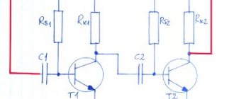
Why this conversation... A large speaker should not just be adapted to one of the channels, but should be given a specialization for bass. As you know, most modern compositions (We don’t take Sound Around) are designed for two channels (stereo playback). It turns out that two identical speakers (small) play the same notes, this makes little sense. At the same time, from the same channel, the bass is lost, and the high frequencies die on a large speaker. What should I do? We propose to introduce passive bandpass filters into the circuit, which will help split the flow into two parts. We take the diagram from a foreign publication for the simple reason that it was the first one that caught our eye. Here is a link to the original site chegdomyn.narod.ru. The radio amateur copied it from the book, we apologize to the author for not indicating the original source. This happens for the simple reason that he is unknown to us.
So, here's the picture. The words Woofer and Tweeter immediately catch your eye. As you might guess, this is, respectively, a subwoofer for low frequencies and a speaker for high frequencies. The range of musical works is covered from 50-20000 Hz, with the subwoofer accounting for the low frequency band. Radio amateurs themselves can calculate the passbands using well-known formulas; for comparison, A of the first octave, as is known, is 440 Hz. We believe that such a division is suitable for our case. I would just like to find two large speakers, one for each channel. Let's look at the diagram...
Not exactly a musical scheme. In the position occupied by the system, the voice is filtered. Range 300-3000 Hz. The switch is signed Narrow, translated as a stripe. To get Wide playback, lower the terminals. Music fans may want to throw out the Narrow bandpass filter; those who like to surf Skype should avoid a hasty decision. The circuit will completely eliminate the microphone loop effect, which is known everywhere: a high-pitched buzz due to over-amplification (positive feedback). A valuable effect, even a military man knows the difficulties of using a speakerphone. The owner of the laptop is aware...
To eliminate the feedback effect, study the issue, find at what frequency the system resonates, cut off the excess with a filter. Very comfortably. Regarding popular music, we turn off the microphone, move it away from the speakers (in the case of karaoke), and start singing. We will leave the high and low pass filters unchanged, the products were calculated by unknown Western friends. For those who have difficulty reading foreign drawings, we explain that the diagram depicts (the Narrow bandpass filter is discarded):
- Capacitance 4 µF.
- Non-inductive resistances R1, R2 with a nominal value of 2.4 Ohm, 20 Ohm.
- Inductance (coil) 0.27 mH.
- Resistance R3 8 Ohms.
- Capacitor C4 17 uF.
The speakers must match. Advice from this site. The subwoofer will be MSM 1853, the tweeter (the word has not been written off) will be PE 270-175. You can calculate the bandwidth yourself. The capital letter Ω means kOhm - no big deal, change the value. We remind you that the capacitances of parallel-connected capacitors add up, like series-connected resistors. In case it is difficult to get suitable denominations. It is unlikely that you will be able to make speakers with your own hands; it is realistic to obtain small resistance values. Do not use coils; we cut out plates of nichrome or similar alloys. After manufacturing, the resistor is varnished; high current is not planned; the element should not be protected.
It is easier to wind inductors yourself. It is logical to use an online calculator, by setting the capacitance, we will get the parameters: number of turns, diameter, core material, core thickness. Let's give an example, avoiding being unfounded. We visit Yandex, type something like “online inductance calculator”. We receive a number of output responses. We choose the site we like, and begin to think about how to wind the inductance of an acoustic system with a nominal value of 0.27 mH. We liked the site coil32.narod.ru, let's get started.
Initial information: inductance 0.27 mH, frame diameter 15 mm, PEL wire 0.2, winding length 40 millimeters.
The question immediately arises, seeing the calculator, where to get the nominal diameter of the insulated wire... We worked hard, found a table on the website servomotors.ru, taken from the reference book, which we present in the review, consider it for your health. The diameter of the copper is 0.2 mm, the insulated core is 0.225 mm. Feel free to feed the values to the calculator, calculating the required values.
The result was a two-layer coil with 226 turns. The length of the wire was 10.88 meters with a resistance of about 6 ohms. The main parameters have been found, we begin to wind. The homemade speaker system is made in a hand-made housing; there is room to attach a filter. We connect a tweeter to one output, and a subwoofer to the other. A few words about amplification. It may happen that the amplifier stage will not support four speakers. Each circuit is characterized by a certain load capacity; you cannot jump higher. The speaker system is designed with a fixed headroom in mind; to match the load, an emitter follower is often used. The cascade that makes the circuit work, full impact on any speaker.
Parting words for beginning designers
We believe that we have helped readers understand how to properly design an acoustic system. Passive elements (capacitors, resistors, inductors) can be obtained and manufactured by anyone. All that remains is to assemble the speaker system body with your own hands. And we believe that this will not be the case. It is important to understand that music is formed by a range of frequencies that are cut off by improper manufacturing of the device. When you are planning to make a speaker system, think about it and look for the components. It is important to convey the magnificence of the melody, there will be a strong confidence: the work was not in vain. The speaker system will last a long time and will give you joy.
We believe that readers will enjoy making speaker systems with their own hands. The coming time is unique. Believe me, at the beginning of the 20th century it was impossible to obtain tons of information every day. Training resulted in hard, painstaking work. I had to rummage through the dusty shelves of libraries. Enjoy the Internet. Stradivarius impregnated the wood of his violins with a unique composition. Modern violinists continue to choose Italian examples. Think about it, 30 years have passed, the cart has been left behind.
The current generation knows the brands of adhesives and the names of materials. Necessities are sold in stores. The USSR took away the abundance of people, providing them with relative stability. Today, advantage is described by the ability to invent unique ways to earn money. A self-taught professional will cut down cabbages everywhere.
Speaker crossover diagram
Crossovers are made based on measurements, here is a diagram.
We put everything together - we insert sound insulation, crossovers, cables, etc. We put on gaskets for the speakers, handles and cable entry. We install the speakers (here on hex screws with nuts).
BR (bass reflector) tunnels are made of PVC pipe, they have rounded exits so that they do not hum, ventilate them, then paint them black with a spray can, then press a black grille into the groove (preferably powder coated), glue strips of black felt on the grille supports so that they did not buzz and the assembly was completed.
As a result, the speakers sound very good. We had a combat test at a wedding, and everyone praised them very much for their sound and capabilities, no one even believed that these speakers were not store-bought!
Speaker phasing
This brings the mixing to an end. All that remains is to decide on the phasing of the speakers. There are at least three ways: by ear, by the shape of the frequency response and by the phase shift at the crossover frequency. If the speakers have a moderately linear frequency response and phase response, and the filter does not greatly increase the phase at the crossover, then when the correct phase changes to an incorrect one, a deep dip will appear at the crossover frequency, it is difficult to miss it. In this case, it is worth adjusting the phase according to its shift. This can be done with an oscilloscope by feeding the horizontal deflection signal from the amplifier, and the vertical deflection signal from the microphone.
A sine wave with the crossover frequency is supplied to the amplifier input and, without changing the relative position of the microphone and speakers, the high-frequency and low-frequency speakers are switched. Based on the similarity of the Lissajous figures, a conclusion is drawn about the equality of the phases of the emitters. This method works well for first order filters. With the curvature of our speakers, this method does not justify itself, so we compare the frequency response at different phasing.
The second option is noticeably worse. However, the first one is not the ultimate dream, but since moving the inductance of the coils is not easy, and it’s too lazy to tinker further, everything was left as is.