An internship is a process of gaining knowledge and experience. Our Raccoon Security team believes that increasing the level of information security of the devices and software around us is impossible without transferring this knowledge and experience to future generations of specialists. That is why we have been organizing individual internships for talented students and graduates for many years.
Security research is a skill that is not taught at university. It can be learned through concrete examples and under the guidance of experienced mentors. Every year, our interns solve complex technical problems, achieve their goals and move on, expanding their professional horizons and making the world a little safer. Each of them has their own story of becoming a specialist, and under the cut is the beginning of one of them.
Last October I started a technical internship at . My interest was directed to the field of reverse engineering. I knew what it was, I had already tried to research crackme on x86 on my own, but I understood that the most interesting thing lies precisely at the intersection of software and hardware. I had no experience in this area, but I had a desire to try my hand.
I didn’t have any specific expectations from this event - friends and acquaintances quite often talk about technical internships in various well-known companies. And when I was offered to try my hand at researching a USB-SATA adapter, I was simply glad for the new opportunity to learn something. The experience I gained and the results I achieved allowed me to be convinced that I had chosen the right internship place and future profession.
The research began with getting a regular USB-SATA adapter. Here's what I did next.
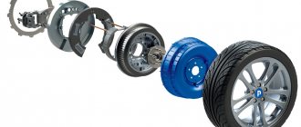
First you need to inspect the adapter board and determine the basic elements of the device. The figures below highlight the main component blocks that are important for the operation of the device. Photos taken after the study:
USB-SATA adapter. View from above
USB-SATA adapter. Bottom view
After spending some time on Google, I found out that there are two voltage converters on the board: one for 3.3 V, the other for 1.2 V. It was also very easy to determine the flash memory installed on the board. The ROM operates over the SPI interface, and the memory capacity is 512 Kbit.
It would seem that the circuit reconnaissance stage is almost complete, but a quick search on the Internet did not produce any results for the query “ASM1051”. We could not find any documents for the chip installed on the board. True, we still managed to find software that allows us to update it. In addition, there is a small datasheet for the older model ASM1053 .
When connected to a computer, the adapter appears as a USB storage device. I decided that a deeper knowledge of USB would probably be useful for my research, so I spent the next couple of hours studying the interface. In general, USB devices can be of different classes depending on their functionality. For example, flash drives are Mass Storage Devices, and keyboards and mice are Human Interface Devices (HID). And since my adapter is visible in the device manager as a storage device, it means it is defined as Mass Storage and should work with SCSI commands.
Basic literature on USB that was useful
- USB in a NutShell
- Universal Serial Bus Mass Storage Class
- USB Mass Storage Class on an Embedded Device
- SCSI Commands Reference Manual
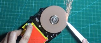
Since nothing is known about the ASM1051 installed on the board, the most obvious action was to read the memory from ROM. I moved to the laboratory. Using a soldering gun, I separated the flash memory chip and connected it to the ChipProg-48 USB programmer. There were no problems reading, and I ended up with a binary file in my hands. At that time, I could not tell what was on the flash drive, and began analyzing the data received.
The first thing I did was open the memory dump from the ROM using WinHex, but you can use any HEX editor. I started looking closely at the bytes:
Beginning of memory dump read from ROM
The picture above is a screenshot from the editor. The line ASMT1051, which starts at address 0x44, immediately catches your eye. You can also see the asmedia line from address 0x18. For primary data analysis, I used the frequency analysis tool available in WinHex.
ROM memory frequency analysis histogram
The histogram shows the bytes that are most numerous in the file. In addition to the heap of 0x00 and 0xFF (the outermost bars on the histogram), the following bytes are often found in memory:
- 0x02;
- 0x74;
- 0x90;
- 0xA3;
- 0xE0;
- 0xF0.
It would be possible to confirm my assumption that the ROM contains the firmware. A simple way to do this is to try to compare opcodes of different architectures suitable for microcontrollers (hereinafter referred to as MCUs) with bytes that are often found in memory.
To roughly estimate, very often in any assembler code you should encounter commands such as:
- mov;
- jmp;
- call;
- ret.
Of course, these commands may have other variations in different architectures, but the general meaning is the same.
I had to go through several sets of instructions for different cores before I found the right ones. Comparison with the Intel 8051 architecture gave a very plausible result. The opcodes of some commands match popular bytes from the file, for example:
- 0x02 – LJMP addr16;
- 0x74 – MOV A, #immed;
- 0x90 – MOV DPTR, #immed;
- 0xA3 – INC DPTR;
- 0xE0 – MOVX A, @DPTR;
- 0xF0 – MOVX @DPTR, A.
It really looks like the ROM contains firmware for the MK. It would have been possible to immediately load the binary in the IDA Pro disassembler, but over lunch one of my colleagues asked:
“Are you sure that the code in memory starts at address zero?”
Indeed, you need to take into account that there may be some kind of “garbage” or data from address 0x00 in the memory.
In general, I was faced with the task of determining the starting address of the code. The best way to achieve this goal was to use the EM100 SPI emulator. The emulator replaces the memory chip on the board, with it there is no need to unsolder the ROM every time you flash the firmware; in addition, the EM100 can record a log of memory accesses. Considering that the firmware from the ROM has already been read, you can now load it into the SPI emulator. Next, you need to solder the emulator to the adapter board and record a log when connecting the adapter via USB to the PC.
The SPI emulator is soldered to the USB-SATA adapter board
I soldered the wires from the emulator to the contact pads from the flash memory and flashed the emulator with the firmware I read. Now it remains to see whether the MK accesses memory, and if so, at what addresses.
Log of ROM memory accesses (obtained using SPI emulator software)
The figure above shows that when power is connected to the adapter, the ASM1051 controller installed on the board sends several 0x03 (Read Data) commands.
First, the ASM1051 reads 0x80 bytes, starting at address 0x0000. Next are two bytes, starting from address 0x0080, then two more bytes from address 0x8082. Then it reads most of the memory from the ROM, starting at address 0x0082.
It can be assumed that the large number of bytes that are read from the ROM last, starting at address 0x0082, are probably the code. What and why is requested before this is not yet clear. What is known is that in response to the first request, the ASM1051 will receive from the flash memory the lines that are marked in the figure above. They were located in the first 0x80 bytes.
It's time to check the guess that the external memory on the board contains firmware for an MK with an 8051 core, and the code itself is located at address 0x0082. Open the memory dump in IDA Pro, specify Processor type Intel 8051 and offset for code 0x0082.
Binary file opened in IDA Pro at offset 0x82
There were no problems opening the binary in a disassembler.
Conclusions:
- The ASM1051 MCU has 8051 architecture.
- There is a code in the ROM that starts at address 0x82. There is something else besides the code.
- The first 0x80 bytes somehow attract attention.
Now that I have made sure that the code is loaded correctly into IDA, I can start analyzing it and commenting it in parallel.
While examining the code, I found simple functions such as subtracting 32-bit numbers, came across various handlers similar to switch() in S. Melkali, and very simple functions like saving a value from the R7 register to memory at some address. I will describe the most significant findings below.
Connection procedure
The first thing you need to do is determine the type of HDD connector that you plan to connect via USB. Plugs come in the following types:
SATA (a more modern connector, used in newly built PCs and laptops);
IDE (can be found mainly in “experienced” PCs).
We will consider the connection using the example of AGESTAR FUBCP, since it supports both “old” and modern HDDs. The average cost of such a device in Russian electronics stores is about 1,500 rubles.
The device is equipped with three interfaces (plugs):
- SATA (7-pin plug).
- IDE 40pin (40-pin plug, for IDE 3.5″).
- IDE 44pin (respectively, 44-pin plug, for IDE 1.8″/2.5″).
Description of AGESTAR FUBCP connectors below.
Dock station
The most expensive, but very effective option is to purchase a docking station. These devices are somewhat reminiscent of old consoles like Dendy or Sega. The similarity is that instead of connectors for cartridges, there are connectors for HDDs. All you have to do is simply insert the hard drive into this station, and then connect it via USB to the computer.
Such devices come in different types, and in many cases you can work not only with one disk, but with several at once, even of different form factors (2.5 and 3.5).
The cheapest options with one device will cost you no less than 1000 rubles, or even more. More powerful stations cost 3 and 4 thousand rubles each.
As you can see, there are enough ways to connect a hard drive via USB to a computer, for every taste and color. So you no longer have to leave all your devices unattended.
Step-by-step connection of HDD to computer
So, we have determined the connector of the connected hard drive; now it needs to be connected to the corresponding connector on the device. After that, insert the USB connector for data transfer (black) into the USB port of your computer or laptop. If we are working with a laptop hard drive (2.5”), we can turn on the adapter, and the HDD should appear in the list of computer drives. Sometimes, with such a connection, the hard drive may not have enough power and will not be detected by the system. In this case, turn off and connect the red USB connector of the adapter to any of the computer ports and turn on the adapter again.
If the connected hard drive was previously installed in a PC (3.5” format), the power supply from your PC’s USB will not be enough for it. The AGESTAR FUBCP comes with a power supply for 3.5" hard drives. To open the hard drive via USB, first connect it to the appropriate connector (IDE/SATA), then insert the black USB cable into one of the USB ports of the computer, then connect to the adapter a power supply that operates on 220 V (plug it into a power outlet) .
After all cables are securely connected, turn on the adapter. The connection is complete, the hdd will be detected by the computer, and you can work with it.
The note outlines in an accessible form simple steps for adapting a USB-to-SATA converter to a form suitable for use using available tools.
Preamble
One day, for some (still unclear) reason, one of the onboard SATA nipples on a self-assembled NAS on miniITX (also an AoE server for diskless clients) failed, and since it was in the evening (and even on a long weekend ) then this imposed certain restrictions on the availability of the solution (although you can fly like a bullet to a convenience store, but laziness, as you know, is the engine of savvy minds).
So, the task is this: connect a SATA screw to a miniITX system in the absence of free SATA.
Part I
Having quickly carried out an audit of the junk around the computer, we discovered such an adapter, which had been collecting dust for many years without use, because it was ordered at the dawn of the popularity of foreign online stores:
As it turned out, the board is not just a USB-to-SATA converter, but is intended for devices such as laptop DVD drives , carrying on board the mating part of the slimSATA
(features an additional non-standard power supply). Thus, it was not possible to connect the adapter to ordinary SATA devices and it was thrown into a dark corner of the box for a long time.
So, the adapter contains a slimSATA connector, which includes a standard SATA 7pin female connector (as on connecting cables):
Even if you remove an additional non-standard slimSATA power connector from the board, when inserted into the HDD, the adapter will block access to the HDD power connector (SATA 15pin). There is only one way out - a SATA 7pin connector extension, for which we carefully cut off one of the ends of the standard SATA cable:
Now you can completely remove the slimSATA connector from the adapter board and solder the end of the SATA cable (without mixing up the RX - TX differential pairs!):
To impart mechanical strength to the joint between the cable and the board, it was decided to use PVC electrical tape (I abandoned the original idea of filling it with silicone sealant - it is unknown how “non-conductive” it is at 1.5 GHz):
Now let's move on to USB: since we need a replacement for internal SATA, a two-meter skein from USB-A to USB-B inside the case will obviously be superfluous. We get rid of USB-B - unsolder a piece of the board with connectors and electrolytes (they are only needed when powering a USB DVD drive).
We will connect the adapter to the internal USB connector on the motherboard. Why do we crimp/solder (for 480Mbit/s it is better to solder) the contacts of the PLS-4 connector (it is more convenient, of course, PLD-10, so that it covers the entire comb at once, but only PLS-4 is present in the household):
After checking the pinout of the comb on the motherboard and the pins of the USB converter chip SPIF225A
, we assemble:
So, after spending some time searching for the necessary pinouts, we quickly built this type of adapter, which allowed us to pick up a fallen HDD without rebooting and, as a result, thanks to its dimensions and getting rid of atavisms, it fit quite harmoniously into the interior of NASa:
Part II
After solving the problems with the NAS and its upgrade, the itching craving for perfectionism prompted me to modify the adapter. Why the necessary connectors were ordered: SATA 7pin male SMD
& . We mark the seat for the SATA connector, we do it in such a way that the holes for the holder pins do not go through the signal tracks on the back side of the board (as they say - try it on seven times, cut one drill):
We strip the copper and solder the holder pins on the back side of the board:
The pitch of the pins of the footprint on the board and the SATA connector is the same, as a result we get a neatly sealed connector:
Let's deal with the USB part. We mark and prepare a place on the board for landing miniUSB-B:
We solder the connector, showing virtuosity when working with a 0.65mm pitch of the miniUSB-B connector:
Some explanations are needed here, so here is the sequence of actions with miniUSB-B:
- We carefully bend the GND contact so that it does not interfere (the material of the legs is fragile - the leg of the first connector broke off when bent) and soldered it to the body - then we solder the body to the GND of the board;
- The ID pin is not used, so we simply pull it out of the connector with tweezers;
- Now it’s a little freer - there are three pins left - they need to be carefully moved apart with tweezers so that there is more space for maneuvering the soldering iron;
- We solder small extension conductors to the D- and Vbus pins, and slightly raise the inputs themselves so that they do not short-circuit to the board after installation;
- We leave pin D+ “as is” - physically, during installation, it falls on the corresponding polygon on the board;
- Now you can mount the connector on the board - we grab the case diagonally, then carefully deal with D- and Vbus.
Practice is the criterion of truth, so we check the correctness of the connections by actually turning them on:
The second version of the adapter turned out to be much more aesthetically pleasing:
Small touch
Everything is fine. Both functionality and aesthetics, but lacking zest. SPIF225A
bridge , I found it: “
pin 36 - HDD Activity LED output
”. Great:
We unsolder the 10K resistor (PullUp to suppress interference on the TriState-pin?) and solder in a chain of series-connected R and LED. A resistor with a value of hundreds of ohms (I took 1 kOhm), an LED cathode to pin 36 of the microcircuit (determined by testing or documentation):
Bottom line
Using the example of adapting a USB-to-SATA converter, a method for quick modification using a minimum of available materials was shown (quickly restoring the functionality of diskless clients), and also demonstrated an approach to a more thoughtful and elegant solution.
In the era of computer technology, the speed of development of ports for communication of the latter is also not slowing down. Another thing is that end users have no need for such a race. Before they had time to buy one device, it was no longer suitable. Today we will deal with sata-usb adapters.
- What you need
- Instructions
- Adviсe
- Worth paying attention
What you need
- Converter chip;
- Printed circuit board;
- Soldering Station;
- Programmer.
Instructions
In order not to bore busy visitors, we’ll say right away that it is much easier and cheaper to go to the nearest computer store, pay the equivalent of a couple of American dollars and get a device that is known to work, spending up to an hour of your time on it.
The following article is for people who cannot tolerate slippery beliefs, those who require proof, or who are simply inquisitive individuals.
1. You should start by getting a converter chip. Since the usb/sata operating protocols are fundamentally different, there is no way to “solder this conductor here, and this one here, and everything will work.” In this case, signal recoding is required, which can only be done by a chip designed specifically for the task of usb to sata recoding. The figure shows one of the varieties of such chips.
2. Now you will need a PCB. This is the “plate” on which the elements are attached. Considering that the board must have a completely custom layout for your device, it is impossible to buy one. How to make the board itself is a topic worthy of 10 more articles and equipment worth a tidy sum (if there is such a thing, great, you’re in luck).
3. To solder the chip onto the board and organize the wiring, you will need a soldering station.
4. Finally, if you are a magician, and you managed to complete all the previous instructions, your magic will continue to be needed. After receiving the finished board, you will need a programmer - a device designed specifically for your board in order to program it specifically for your specific needs.
If you have completed all the steps and are bored, can you try making a sata ide and vga to tulip adapter yourself? We read, find out, try, and report back on the results.
The cost of producing a device with your own hands, not taking into account all the equipment, will exceed the store price tag by 30-200 times. Is it worth it?
Clearly.
Worth paying attention
You will have to perform each step of this instruction 15 times, since the work involved is microscopic, and a stray speck of dust will negate all the work done. Perhaps, if you have nothing to occupy your inquisitive mind, you should make something simpler, for example, a homemade robot?
How to make a sata usb adapter with your own hands2.90 out of 50 based on 29 voters. Thank you for the article - like it. A simple click, and the author is very pleased.
Find No. 4
Knowing that MK can process non-standard commands, I wanted to find out what they do. Most of them won over to me quite quickly. I will not provide a study of the code of these commands, since it is long and could be material for a separate article entitled “Assembler is easy”; I will describe the results obtained in the table below.
| SCSI command | Command Description |
| 0xE0 | Allows you to read the first 0x80 bytes from ROM. In the future, I will call this part of the memory the preamble (yes, those same 0x80 bytes that contain the asmedia and ASM1051 lines) |
| 0xE1 | Writes the first 0x80 bytes to ROM |
| 0xE3 | Writes any number of bytes into ROM memory from address 0x80. The size of the parcel is passed as an argument (as it turns out) |
| 0xE4 | Allows you to read a block of bytes from the ASM1051 RAM memory. Takes as an argument the starting address and the number of bytes to read |
| 0xE5 | Writes one byte to RAM at address |
| 0xE7 | Reads the last received packet into the ATA buffer |
| 0xE8 | Reboots the device |
I admit that I did not figure out all the commands by reading the functions in IDA. Having run into a wall during research, I remembered that I had seen software and a lot of firmware for the ASM1051 when I was looking for documentation for it. Using the found software, you can update the firmware and reboot the device. So I decided it was time to use Device Monitoring Studio and see what the PC is sending to the adapter during the update.
Thus, we were able to understand how the firmware update process occurs: first, the preamble is sent (by command 0xE1), then the code is written by command 0xE3, then the whole thing is polished by rebooting (command 0xE8). For quick and convenient updating, I wrote a Python script that inserts the necessary lines into the preamble, then reads the check amounts and updates the device. Now I no longer need an emulator, I have the opportunity to upload firmware to the ASM1051 via USB, and I can return the native ROM to the board.
conclusions
To update the firmware, you need to execute three SCSI commands in sequence: 0xE1, 0xE3 and 0xE8.
How to make a sata ide adapter. Do it yourself
The hard drive is responsible for storing information on your personal computer. Progress, as we know, cannot stand still, so its speed and reliability are constantly improving. The change of generations also entails a change of interfaces. Today we’ll talk about sata ide adapters.
- What you need
- Instructions
- Adviсe
- Worth paying attention
What you need
Instructions
Let's not hide the fact that Sata connectors are a development of ide connections; the latest standard, however, is correctly called ATA. After the Sata interface appeared on the market, ATA was renamed PATA. As you may know, the bus on which ide runs boasts an operating frequency of 33MHz. If we return to the sata interface, the operation of its bus is determined by a frequency of 1.5 GHz. The difference, you see, is significant.
This immediately dismisses the possibility of the concept of “adapter”, because it is impossible to passively connect two devices operating at different frequencies - for this they use a special device called a converter. Its task is to convert the incoming signal of one protocol into another, understandable for the second device
1. Let us clearly show in the figure what a standard converter adapter for ide and sata consists of.
2. As you can see, the front part is responsible for connecting the ide cable, the rear is for sata. The microcircuit in the center of the board is the controller responsible for converting the incoming signal into the desired output signal. You may also notice the power connector - it is needed for the crystal oscillator (the shiny “bathtub”) and the controller.
3. Do-it-yourself work does not stand up to criticism after finding out the cost of the device in the store. The proof below should completely discourage you from wasting a lot of your time on a fairly easily accessible and cheap device.
The price of $4-$15 is an excellent indicator.
Also find out if you can make an adapter from vga to tulip and sata usb with your own hands.
Remember that any electronics production at home cannot boast of proper safety. You will have no one to complain to if your hard drive and controllers on the motherboard burn out due to the connection of a foreign device.
If you smell something fried, check your CPU temperature.
Worth paying attention
You can clearly see another representative here.
How to make a sata ide adapter. Do it yourself3.00 out of 50 based on 10 voters. Thank you for the article - like it. A simple click, and the author is very pleased.
DIY Sata cable
Greetings to you friends, readers and visitors of my blog. In this article I will talk about sata cable. As you know, all computer technology manufacturers have long switched to sata power supply.
This article will describe all the nuances of creating a sata cable, or also called a sata adapter, with your own hands. And so let's begin the process.
Sata cable or sata adapter
First, we need a non-working PC power supply. And you need to pull out the longest sata cable from the power supply.
The longest cable is desirable, but if this is not available, of course a short one is also possible.
In most cases, it happens that some other connector is connected to the sata cable. You can leave it on and remove it if you don’t need it or get in the way for some reason.
In my case, two wires on the additional connector were cut off and in order to get rid of the unnecessary Molex connector I had to disassemble the sata adapter.
Sata cable disassembly
This connector is very easy to disassemble. All the wires on the sat are on plastic clips that need to be lifted with the tip of a pair of scissors.
Without letting go, pull the wire back; without force and without damage, the wire is carefully removed from the connector.
To cut off the excess wires from the Molex, I use a tool in the form of wire cutters from the women's manicure set. You can also use small electrical wire cutters.
Once all the excess wires are cut off, insert the wires into place. Be careful when removing wires, do not remove them all at once, otherwise you will get confused.
Remove one wire, cut off the excess and insert it back. And we clean the cut ends of the wires for soldering.
Molex disassembly
We will connect the cable made using sata to our computer power supply via a Molex connector
To do this you will have to disassemble the molex connector itself. We take the free Molex connector on the power supply and disassemble it. The lugs on the wires in Molex have tabs or tabs,
which keep them in the connector itself. To remove the four wires we need to find these tabs and bend them inside the tip. To find this ear, use a bright flashlight.
If the ear is not located, use a thin screwdriver or scissors around the tip
Once all the wires are removed, you need to solder the cleaned ends of the sata cable wires. Solder each wire by color. If for some reason you were unable to sing, you can do the following. We take the wires of the sata cable, clean their ends by about 1.5 cm and screw them onto the tip of the molex and twist them so that they do not slip.
As we said above, the tips of the Molex wires are held on the ears in the connector and therefore, before putting the wires in place, you need to bend the eye on each wire
We assemble the molex connector and connect sata power. All that remains is to check the sata adapter. In my case, everything works to this day.
How to quickly make a sata cable
There is another option to make a sata adapter. To do this, take a sata cable as usual, clean the ends by about 1.5 cm, twist the ends of the wires so that
Attention, this method is not safe since at any time the wire can jump out of the plug and short-circuit.
Do not use ordinary glues, otherwise it will be very difficult to disassemble the connector.
For what reason was the article written?
I once encountered cases where my power supply did not have enough sata cable for power due to hard drives.
It would be an option to transfer the cable from one hard drive or go to the store and buy a sata adapter.
But since I like to create things with my own hands, I decided to make this cable myself. And step by step the process went along the flow.
life-pc.ru
Find No. 1
Interestingly, in response to my INQUIRY (SCSI command) request, I received a response containing two lines that we saw at the beginning of the ROM memory. Of course, I immediately changed these lines in the emulator’s memory, expecting to see what I wrote at the INQUIRY request. Such a naive dream quickly collapsed. Now, in response to the command, I saw a different line, the ASM1051 did not request most of the memory from the ROM. MK read only the first 0x80 bytes and that's it. The 8051 architecture can use masked (hardware) firmware; apparently, the ASM1051 started booting from it.
So it became clear that the first 0x80 bytes are really important, and changing them simply won’t work. I decided to take a closer look at the requests that the MK makes via SPI before loading the code.
SPI data request to ROM
Two requests for two bytes seemed interesting. A search in IDA for 0x00, 0x80 and 0xEB yielded a huge number of results, which I did not analyze, but byte 0x5A came up less frequently.
Comparison with byte 0x5A. Counting checksum-8
Literally the sixth click brought me to the section of code shown in the figure above. It can be seen that the value from the register with address 0x80 7E is compared with 0x5A. Then checksum-8 is read for the values located from address 0x80 04 to 0x80 7E . Next, the value at address 0x80 7F is compared with the previously obtained amount.
Beginning of memory in ROM
Such offsets were reminiscent of the beginning of a memory dump from ROM. In the figure above you can see that address 0x7E contains byte 0x5A. And if we calculate checksum-8 for bytes from position 0x04 to 0x7E, we get 0xA7, and this value is located at address 0x7F.
In a similar way, we were able to find the calculation of the checksum for the bytes from address 0x0082 to 0x807F (apparently this is the whole code), which is checked against the byte at address 0x8083. And at address 0x8082 the value 0x5A again lies.
Yes, this is a little more complicated than just changing lines in memory. I also changed them, but I also calculated the check amounts for the new file and wrote them down in the right places. After that, in response to the INQUIRY SCSI command, I saw my lines.
Conclusions:
- During boot, the ASM1051 attempts to load code from the ROM.
- First, the ASM1051 compares the checksum-8 byte from address 0x04 to 0x7E with the value at address 0x7F.
- If the comparison of the check amount for the preamble is successful, then you can read it for the “code” (addresses from 0x0082 to 0x807F). ASM1051 compares this amount with the value at address 0x8083 and checks that byte 0x5A is located at address 0x8082.
- If all checks are correct, then the ASM1051 boots from ROM, otherwise it uses masked firmware.
You need to connect an external HDD 2.5 x 500 GB to the laptop. /hdd:
sata esata hdd sandbox
You need to connect an external 2.5 500 GB HDD to the laptop. It is not advisable to shell out money to buy an adapter, but something made by yourself always gives a + to your mood when using it)
Here is the hard drive itself with a SATA connector
The 5V USB power connector seems to work, but is it possible?
And the most difficult thing is how to connect the part through which information is transmitted to the laptop? There is a SATA adapter
I thought about cutting and soldering the eSATA input and connecting it to the laptop, but again the question arises: is this possible? I rummaged through the net, some write what is possible, some write what is not. If there is such a possibility, what wires go where? and are there other ways? Maybe someone can post a simple diagram? More details
Expand
joyreactor.cc
Adapter or new drive?
There is no clear answer to this question. It all depends on your preferences and budget. Nowadays, memory prices have dropped significantly, but they are still not encouraging in some respects. Perhaps a more rational solution would be to purchase a new drive or docking station, which will allow you to quickly connect hard drives of different formats like a flash drive.
It is worth considering that buying a new hard drive may entail an upgrade of the entire system, while installing an adapter does not oblige you to anything.
Make a sata usb adapter with your own hands photo
You can make an external hard drive yourself using regular SATA 2.5 or SATA 3.5 drives + a special cable or an external enclosure for the HDD.
Let me explain for those who don’t know:
SATA 3.5 are regular hard drives that are used in your computer.
SATA 2.5 is a smaller version of the hard drive, used in laptops.
If you purchase a simple USB-SATA adapter cable in the store, any hard drive can be used as an external one, connecting it to any computer.
The method described above can be used, for example, to recover data, check disks for serviceability, or use them as a removable hard drive. The last option is not entirely convenient. Since the external device must also have a beautiful case.
Let's go to the store. We buy a case for an external hard drive and plug SATA 2.5 into it.
For example, I purchased a case for 300 rubles that allows operation at USB 3.0 speeds and inserted a 160 GB hard drive from an old laptop into it.
What happened in the end is clearly visible in the photos.
Alexander Borisov, Samara
Especially for the site.
If you are going to purchase accessories for computer repair, then a SATA USB adapter is the first thing you need to pay attention to. Such a device allows communication between the two most common interfaces. The SATA standard is used on almost all internal drives of personal computers and laptops. All modern PCs are equipped with USB ports.
What can this adapter be used for? This is exactly the tool you will need in case of hard drive failure. If things go wrong with the HDD, there is a high chance that the computer will become unbootable. In this case, you will have to replace the disk, but the information that was stored on the previous drive will be lost.
If the HDD is partially damaged, this does not mean that all files on it are lost forever. By using a USB to SATA adapter, you will likely be able to recover most of your data. Even if the disk does not initialize, there are many free programs that will allow you to scan partitions and detect any information that can be recovered.
Hardware failure is not the only reason to use an adapter. For example, a user may want to upgrade to a larger and faster SSD drive. Using the adapter, you will be able to transfer all the old data to the new disk yourself, without turning to specialists for help. In addition, HDDs have become incredibly cheap. Any user who regularly updates their computer usually has at least 1 drive with a capacity of more than 500 GB. With this simple adapter you can turn your HDD into an external drive to access your old files.
Find No. 5
In addition to undocumented commands, it was interesting to look at standard command handlers.
Move the third bit from register 0xC884 to the seventh bit of register 0x8002
There is one interesting check in the MODE SENSE(10) SCSI command handler. The figure above shows part of the function code. It can be seen that the third bit is read 0xC884 Then the value of this bit is set to the register at address 0x8002.
The interesting thing here is that register 0xC884 is not initialized anywhere in the code, which means that it is most likely hardware.
Table 362 from SCSI Commands Reference Manual
In addition, if you look at the documentation for the SCSI command 0x5A (MODE SENSE), it becomes clear that the USB-SATA adapter must respond to the MODE SENSE request. The third byte of the response contains the seventh bit WP (Write Protect). By the way, I have already seen the entry of the seventh bit in 0x8002, and the offset from the beginning of the USB buffer (0x8000) is exactly 3 .
Conclusion:
The USB-SATA adapter under study reads the third bit from the hardware register at address 0xC884 and sends it to the USB host as the WP bit.
Anker USB 3 to SATA Converter
Not all SATA USB devices are created equal. Some use an outdated standard that negatively impacts throughput. Others may not be compatible with newer drive types. There are varieties of adapters that stand out from the rest. First of all, you should pay attention to Anker USB 3 to SATA Converter Adapter Cable.
Studying Anker products, one can come to the conclusion that the company has no shortage of components and peripherals for computers. Judging by numerous reviews, users rate everything from chargers to cables or adapters very highly. You may not have seen the products of this company in local retail outlets, but you can easily find them in online stores.
Anker's USB to SATA adapter is a simple device that gets the job done. The adapter is equipped with only the most necessary equipment, and there are no unnecessary components. The developers have done everything possible to ensure that the device copes perfectly with the task assigned to it. The USB SATA adapter is a black rectangular box. This allows you to place it on a flat surface, preventing the drive from detaching during use.
There are 2 cables that can be connected to the back of the device: USB 3 for data transfer and an optional power cord for use with high-power drives. The cables are reliable and durable, making this adapter useful even if the distance between the computer and the SATA 2 device is short (causing the cables to be bent). Thanks to its impeccable design, the device will look great in an office or digital repair shop.
Adapter capabilities from Anker
Unlike some other adapters on the market, Anker comes with a hardware SATA 3 controller. If the device relies on software to convert the signals, this can lead to performance and compatibility issues. Luckily, the Anker hardware controller used is standard and has been thoroughly tested with a variety of devices. This means that almost any computer or drive that can be physically connected to this adapter will work. Thanks to the built-in power adapter, the device supports both 2.5- and 3.5-inch drives.
The USB 3 port is only capable of delivering a relatively small amount of power. This is enough to power compact 2.5-inch drives and SSD drives. But 3.5-inch devices will require a little more power, and a power adapter will help in such a situation. In terms of compatibility, you can use hard drives, SSDs, Blu-Ray drives, DVD recorders, and combo drives. The adapter works with almost all operating systems from Microsoft, from Windows 98 to Windows 10. Mac OS is also supported. Theoretically, there is no reason to think that a SATA to USB adapter will refuse to work with Linux, but this system is not officially supported.
Thanks to the USB 3 interface, data transfer occurs according to an accelerated procedure. The theoretical limit is 5 Gbps, but this is quite difficult to achieve in practice. When using an SSD, read speeds are typically around 350 Mbps and write speeds are around 250 Mbps. Record data transfer rates can only be achieved if you use the fastest SSDs available on the market. In cases with regular PC hard drives, the maximum speed is 120 Mbps for reading and 100 Mbps for writing. In this case, the reduction in USB throughput is not due to the adapter, but to outdated HDD technology.
There are not many additional functions on this adapter, because simplicity is its main advantage. The operating system does not recognize it as an adapter, but simply sees a standard external drive via USB. This means that all built-in backup software will work without interruption. You can use any data recovery program or create images without any special drivers or settings. Due to the lack of drivers, the SATA USB adapter will operate in safe mode, making it ideal for diagnostics and repairs.
eSata adapter
Another convenient way to quickly connect drives and various drives, but for some reason not widely used. To do this, you need to install a bracket with eSATAp connectors on the front or rear panel of the computer and connect the appropriate SATA cables and power (Fig. on the left). The drive or drive is connected using a special eSATAp cable (picture on the right). Pay attention specifically to the eSATAp option, which allows you to connect 3.5-inch drives and drives that require 12V power. The main advantage of this method is the complete absence of delays, since third-party controllers are not used during operation.
Hard drives with a SATA connector are still quite relevant, but models with a small capacity are of no practical interest and only get in the way. They make constant noise, they heat up and heat up neighboring elements, and also require a wire to connect. Therefore, it is more advisable to connect them as needed.
This adapter is an analogue of the first one, but is designed only for connecting 2.5″ SATA drives. Has a combined SATA connector (power + data). An interesting feature is the presence of an additional USB 2.0 “tail” for connecting power-hungry drives.
As an example, connecting a small capacity SSD drive:
This is the most universal model, allowing you to connect almost all different drives or drives with IDE and SATA interfaces. An additional 12V power connector is located on the reverse side, and a power supply is included.
A very convenient device for quickly connecting drives. There are many different models, differing in both external design and the bridge used. They come in closed and semi-open housings made of plastic or metal. There are models for both 2.5-inch drives and 3.5-inch hard drives. The connection to a computer is usually carried out via USB 3.0.
On sale you can find so-called “external drives” - this is nothing more than a container (external box) with an installed drive under your own brand. But the drives there are not always good and disassembling them is problematic.
A docking station is a more aesthetically pleasing option for adapters, but at the same time more expensive and more functional. Drives are usually inserted from the top. Hot plugging supported. There are options for both 2.5″ drives without external power supply, and for 3.5″ hard drives with a separate or built-in power supply. There are models for both one drive and several.
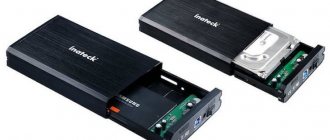
Inateck USB 3 to IDE/SATA Converter
The Inateck Universal USB 3 to IDE/SATA Converter is created by a popular peripheral device manufacturer that develops not only consumer, but also professional devices. Many of Inatek's products offer advanced functionality, while its prices are comparable to its competitors.
Despite the large number of options, the adapter is compatible with all types of operating systems and drives via USB. The only major difference between the adapter and other similar devices is its support for IDE drives. Such drives have long gone out of fashion, but they are still used by some users. This connection standard is used for PCs, laptops, CD and DVD drives, as well as devices that read floppy disks.
Many adapters are only compatible with small IDE drives because they don't have a power connection. But in this case, thanks to a special power cable, you can easily use not only 3.5-inch, but also 5.25-inch drives. The adapter works with OSX, as well as operating systems from Microsoft, from Windows XP to Windows 10.
A hard drive or hard drive is an integral part of any computer.
It is also one of the most expensive components, so incorrect selection, connection and use can lead to failure of both the hard drive itself and the computer. And this is very unpleasant and costly. To prevent this from happening, this article will cover the main ways to connect hard drives to a PC.
Multicombines
One of the most functional devices. The main difference from the previous ones is its small size and the ability to operate autonomously due to the presence of a built-in Li-Ion/Li-Pol battery. As a rule, multi-harvesters are designed to install one 2.5″ drive (HDD or SSD) and allow you to access it via a wired connection via USB or Ethernet, or via wireless Wi-Fi. Very convenient for those who constantly travel or are on business trips.
To organize network access, the multi-harvester has a built-in router, which, when connected to an RJ-45 (Ethernet) Internet cable, can distribute the Internet to nearby devices, that is, it can work as an access point. To view the contents of the disk, just activate the Wi-Fi network on the device and connect to it from any gadget, be it a smartphone, tablet or netbook. After this, you can view files and folders through the standard manager. If necessary, the multi-harvester can be used as an external battery to charge dead devices or gadgets via the provided USB output and a universal cable.
Source
Types of connectors for connecting hard drives
So, the main connectors for transferring data between the motherboard and the hard drive are SATA and IDE. IDE is an outdated version of connectors. Now they are practically not used. Only if you are assembling a PC from used components, you can also purchase a disk with such a connector. It may cost a little less than SATA. Also older motherboards may only have an IDE connection. In this case, you need an appropriate disk. Sometimes, of course, you can purchase different adapters, but this is an extra headache and additional expenses, and sometimes the equipment does not work correctly. SATA connectors are more modern and, accordingly, have a higher data transfer speed than IDE. It can reach 3 Gb per second. The SATA data cable looks like this. The cord is small in width. Connectors consist of a minimum number of contacts. The L-shaped connector connects to the hard drive. Direct - to the motherboard. Complete connection is accompanied by a loud click. To pull out the cord, you need to press the metal lever on the connector and gently pull. When disconnecting, you should not use a lot of force, as you can tear out the socket itself from the motherboard. You need to make sure that the latch is completely out. The IDE cable has a wide cable and a large number of contacts. To avoid connection errors, the connector has a side cutout. Most often, cords have several connectors. One for the motherboard and two for IDE devices, - two hard drives or a disk and a CD/DVD drive. As for motherboards, they can have: 1. IDE only; 2. IDE and SATA; 3. SATA only. The latter is applicable in modern top-end motherboards. Having such a board, there is no point in buying a drive with an IDE connection, even if it is temptingly cheap.
Content
Fast SSDs are increasingly replacing hard drives from use. Even modern hard drives are gradually losing popularity, what can we say about outdated models, which are not always supported by modern motherboards. However, sometimes you need to use an old HDD, but it’s not clear how to make it work. This material contains all the most useful ways to connect both outdated and current drives and drives.
The adapter is designed to connect the oldest types of hard drives or CD/DVD drives with an IDE interface to a computer. Considering that modern motherboards do not have such a connector at all, connection problems may arise. 2.5″ drives are connected directly to the adapter, 3.5″ drives and drives require additional 12 V power, so you must also connect a Molex connector to the hard drive, which is not always convenient. For these purposes, it is better to purchase a separate power supply with an adapter or take a closer look at the more convenient adapters below.
Connecting the hard drive power cord
It is not difficult to guess that the power connectors in these two types of drives are different. For an IDE, it has four Contacts in this form and they are quite powerful. For SATA, the connector is wide and rotated at the edge. Thanks to this twist, it is almost impossible to connect the cord incorrectly. Much at this point depends on the power supply. Early ones may not have connectors for SATA devices at all. But it's not a problem. This is where a special adapter comes to the rescue. Its cost is cheap. Modern power supplies already have several SATA cords. All this must be kept in mind when assembling a PC, so that there are no problems with incompatibility and subsequently wasting money on different adapters.
Backup
I can't help but say about the backup system, which is also provided by this adapter. The most observant readers may have noticed a small black “ backup”
on the device’s body (
see photo with captions above
). So, clicking on this button allows you to launch a utility for copying files from your computer to a connected hard drive. Of course, before this, the program must be installed from the disk that comes with the kit.
To install you need to run the file “ Setup.ex”
e" from the folder "
PCCLONEEX_LITE_2_01_31_JMICRON/PcCloneEx
". The following is a completely standard installation process, which I will not dwell on.
After the program is installed, you need to click on the “backup” button. A window appears asking you to select files for backup.
After you have checked the files or folders, click on the adapter button again and confirm your action in the pop-up window. When copying is complete, the program will display a corresponding message. Later, when the program is minimized, double click on “backup”
starts backup of previously selected files
in the background
.
To be honest, the advantage of such a copying system is very doubtful, but it’s still nice that the developers have provided for it.
Yes, by the way, the cost of this USB adapter is about 600 - 700 rubles. Only you, dear readers, can judge whether this is a lot or a little, but I don’t even question the usefulness and convenience of this device.
To access the contents of your hard drive via USB from a PC or laptop, you will need a special device - an adapter. The connection is not complicated, the main thing is the presence of a special device. There are several types of devices that allow you to connect the hard drive (hard drive, HDD) of a desktop computer or laptop to USB and open its contents. Here are the two most popular: a universal USB controller (for example, AGESTAR FUBCP) or a case adapter (SATA External case, ITEC MySafe Advance and others).
In China you can buy the following devices that are built-in instead of a laptop disk drive:
There are also combined options with a complete set (adapter, cord, power supply).
The advantages of the first one are that such a device is cheaper than a case adapter, and often supports several types of connections (SATA, IDE). However, using a regular hard drive as a portable drive with it is problematic, since it will not be protected by anything.
The second option is a case adapter, which is specifically designed to turn a hard drive into a portable memory device with a sufficiently large capacity, since the case will reliably protect it from dust and mechanical damage. But at the same time, the versatility of the device suffers: before purchasing, you will have to decide which connector the purchased adapter will support.
Using a hard drive in a cased version is a fairly simple procedure, so let’s look at how to connect and open a hard drive via USB using a universal adapter (using the example of AGESTAR FUBCP).
Installing a Hard Drive
We select a “shelf” in the case where to install the hard drive. A setting that is too low will not dissipate heat well enough from the bottom of the drive. Overheating is not allowed. Mounting too high can be difficult due to RAM strips and other hardware. It all depends on the features of the motherboard and the connectors on it. Avoid static electricity, which can damage not only the hard drive but also other PC components. To do this, remove synthetics and woolen items. Also, before each manipulation, touch a grounded object - this could be a heating radiator or a water tap. This way you can remove static from yourself. Carefully insert the disk with the open part down, and try to align the holes on the case with the threads on the hard drive. When everything matches, tighten the screws. It is very important that the screws are not too long, otherwise the drive may be damaged. Typically a 3mm screw length is recommended. Be careful when handling the hard drive. Excessive shaking, shocks, falls, etc. can damage an expensive device. When the screws are tightened and the hard drive is tightly secured in the case, connect the cable. First to the motherboard, then to the hard drive. Connection of SATA connectors.