Using sandpaper from the hard drive of a personal computer, you can edit and sharpen hand tools, knives or small parts. The main advantage of the device: its manufacture requires a minimum amount of tools and auxiliary materials. In this case, the performance of the hard drive does not play a special role: its functions will be completely different.
Modern computer hard drives are not very well suited to realize the idea. The fact is that on HDDs of the first generations, magnetic circles were large in size. This allows you to expand the range of processed elements.
What you need for work
To assemble the sanding machine, you need to prepare the following materials:
- HDD;
- abrasive material;
- standard power supply;
- power supply connection kit;
- materials for assembling the protective casing (at the request of the master);
- rubber caps as a support for the future machine;
- controller for the drive.
Purchasing the last item depends on the type of hard drive. We are considering the use of a brushless drive that will not operate on standard DC or AC voltage. The controller is a special unit that generates voltage at a special frequency for the uninterrupted operation of the electric motor. It operates on a voltage of 9–12 V, depending on the characteristics of the specific model. The cost when ordering from China is $2.8–3.2.
The main advantage of the controller is the built-in function of manually adjusting engine speed.
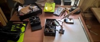
During the work process you will need the following tool:
- a set of screwdrivers for disassembling a hard drive;
- small drills;
- screwdriver;
- soldering iron;
- glue.
Power connection
- Use a standard personal computer power supply of a suitable format.
- Disassemble the unnecessary power supply of any household appliance that operates with a voltage of 12 volts. The board is removed from it and integrated into the existing electrical circuit of the machine by soldering electrical wires. Do not forget about installing the standard power supply socket in the machine body.
After this, you can begin testing the invention. Please note: the direction of movement of the drive can be changed using the controller switch.
Using this machine it is impossible to process a massive tool. The reason lies in the low power of the classic engine: it runs on ferrite magnets, which have never been particularly strong.
Powerful drives are equipped with magnets made from rare earth elements.
An alternative option is to replace the existing winding with wires with a larger cross-section. This will increase the current.
How to disassemble a hard drive
With the right tools, the disassembly process is a simple task.
First of all, you need to remove the top cover. Modern models are mounted on several bolts with a hex head. Older versions are designed to use a classic Phillips screwdriver. If the disk has never been disassembled during the entire period of operation, quite serious efforts will have to be made when removing the cover: at the factory, the screws are tightened with a high tightening torque.
The next stage is complete disassembly of the hard drive. It includes the following steps:
- We dismantle the dust collector. In the image it appears as a small white piece. Its function was to filter the incoming air from small fractions that could damage the hard drive.
- We remove the neodymium magnets and the electronic control board. Its performance does not matter: it will not be of value for the future electric emery. Exceptions will be discussed below.
- Remove the read head and all pins except the power supply.
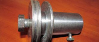
After the work, a bare body with a drive and disks should remain.
Hard disk grinding machine. DIY grinder
If you have an old non-working or unnecessary computer hard drive lying around, then instead of throwing it away, you can make a mini grinding machine out of it with your own hands. Even if you don’t need it, you can find out from this article how you can start the engine from a hard drive. Such a machine will certainly come in handy at home or in the workshop for sharpening knives, scalpels, drills, chisels, screwdrivers and other tools. Besides, it won’t take up much space, if you’re interested, let’s make a grinder from an old hard drive with your own hands.
Hard disk grinding machine. DIY grinder
Parts and tools:
- Old hard drive;
- Electronic speed controller - buy on Aliexpress;
- Servo tester - buy on Aliexpress;
- Sandpaper;
- Double sided tape;
- Two banana connectors;
- Screwdriver Set;
- Soldering iron;
- Dremel;
- Multimeter.
Hard disk grinding machine. DIY grinder
How to make a grinding machine from a hard drive, step-by-step instructions:
Before you start creating a grinder, make sure that the plates on your HDD are aluminum, as some HDDs may have glass plates. How to check this, there are several ways to do this:
- Take a strong neodymium magnet and bring it to the pancake, if the disk is aluminum then you should feel a slight resistance (due to eddy currents);
- Look through the pancake (round disk) at the sun or bright lighting; if it turns out to be glass, it will transmit a little light, if not, then there will be no gaps at all;
- If you can sacrifice one pancake, then put on safety glasses, clamp the disk in a vice and try to bend it a little with pliers; if it turns out to be glass, it will collapse, if not, it will simply bend.
The first thing you will need to do is disassemble the HDD, to do this, take a set of screwdrivers and select a Torx screwdriver of the required caliber, unscrew the top cover of the hard drive, probably one screw will be under the sticker.
Next, we need to pull out the insides of the hard drive, unscrew all the screws and take out the magnetic head with neodymium magnets (don’t throw away the magnets, they can probably be used somewhere else).
Hard disk grinding machine. DIY grinder
Hard disk grinding machine. DIY grinder
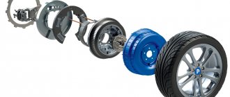
Also remove the discs themselves (pancakes) and spacers, since we will have to reassemble them in our own way.
Let's figure out how to connect the engine from the hard drive. The motor in the hard drive is a brushless DC motor and its windings are usually connected in the form of a star or delta.
Hard disk grinding machine. DIY grinder
The HDD motor can be easily controlled using the Electronic Speed Controller (ESC). Moreover, it can be controlled by a servo tester and as the name suggests, it is used to test servo motors but still, the type of control signal for controlling motors and servos is the same: it is a simple PWM signal. In the case of a servo drive, a certain signal corresponds to the position of the lever; for an electronic speed controller, this corresponds to a certain speed.
Hard disk grinding machine. DIY grinder
Let's focus on the motor wiring, depending on your hard drive you will have one of two types which we will define by the number of pins:
Hard disk grinding machine. DIY grinder
- If your motor has 3 contacts, then it is a triangle topology: there is a coil between each pair of contacts. This is the simplest option: you just need to solder the 3 wires from the ESC (blue) to the 3 motor pins (a, b, c in the diagram).
— If the motor has 4 contacts, then your motor has a star topology. We will need to connect the electronic speed controller to points a, b, c as indicated in the diagram. To do this, we must determine which 3rd of the 4 contacts they correspond to. To find out, we need to take a multimeter and measure the resistance between the contacts. As we can see in the picture, 3 combinations give a resistance of 1 ohm, and the other 3 give 2 ohms. 1 Ohm is the resistance of 1 coil (1 of Z in the diagram), and 2 Ohms is the resistance of 2 coils connected in series. Conclusion: the combinations that we measured - 2 Ohms, are the ones we need (a, b, c in the diagram)!
Assembling a mini-emery machine from a hard drive
After preparing the necessary tools and materials, you can begin assembling an electric sharpener from a hard drive.
The process begins with preparing the abrasive surface. There are two options:
- The nozzle is cut from a sheet of sandpaper along the contour of the disk. An additional hole is made in the center.
- At a hardware store you can purchase a set of abrasive wheels for an angle grinder and adjust their size to the specified parameters.
The discs themselves can be made of aluminum alloy or glass. We recommend covering the discs on all sides to obtain a larger number of processing surfaces. This will increase the replacement interval. To expand your processing capabilities, use abrasives with different grits. By purchasing extra sandpaper, you can make removable attachments from the remaining material.
To attach the attachment to the disk, you can use any universal glue.
After preparing the disks, they are installed back in their original place, tightening all the screws.
Then you should start making the housing for the controller. The simplest option is to buy a junction box measuring 100*100. These dimensions are enough to comfortably accommodate the controller, power socket and engine speed control mechanism. Fans of modern technology can design the case themselves and print it on a 3D printer. It is attached to the hard drive with standard bolts.
The last step is to install rubber feet, which will dampen vibration and provide additional stability during operation. You can order them on Aliexpress or make them yourself.
Selecting a controller and connecting the HDD motor
Hard drives (hard drives) have a three-phase low-voltage motor. Therefore, to rotate it, you need a voltage of 12 V three-phase current, which can be obtained by converting DC voltage using a controller made on microcircuits. The circuit is simple, but I didn’t want to develop it and manufacture it.
And then on Aliexpress there appeared an inexpensive controller suitable in parameters and dimensions for three-phase motors, designed for a supply voltage of 5-15 V with a load current of up to 2 A. In addition, with a manual PWM speed controller from 0 to 10,000 per minute and overload protection. Model ZS-X9B.
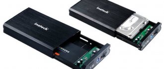
For a homemade sharpener, any 3.5-inch hard drive from a desktop computer is suitable. Moreover, the older the disk and the smaller the capacity, the better, since older ones have more powerful motors.
The hard drive label usually indicates its current consumption in the 5 V and 12 V circuits, taking into account the consumption of the control circuit. The motor current consumption will be less. When a hard drive is found, you need to check that its current consumption through the 12 V circuit does not exceed 1 A. The hard drive shown in the photo, taken for homemade use, consumes 0.75 A.
After receiving the controller board from China, you can begin manufacturing the sharpening machine. Start by unscrewing all visible and invisible screws on the hard drive case.
To do this you will need a quality screwdriver with an asterisk. The screws are unscrewed with great force and with a cheap screwdriver all the edges of the sprocket will immediately be cut off. One of the cover screws is usually located under the label, and to find it you need to easily run your finger along its surface to find a soft spot on it and break a hole.
Next, the mechanism that controls the movement of the magnetic heads is dismantled. To do this, unscrew the screws securing the neodymium magnets, after which the mechanism is easily removed from the axis. All that remains is to remove the adapter block connecting the magnetic heads to the printed circuit board.
The removed neodymium magnets are glued to steel plates, and despite their small size, they have a strong attraction force for ferrous metals and are useful in the household. I previously disassembled hard drives because of these magnets.
A printed circuit board is installed on the bottom side of the hard drive using several screws. If you apply a supply voltage of 5 V and 12 V to its four-pin connector, then in some models the engine will start, but after a while it will stop due to the lack of an access signal from the computer to reduce wear. In addition, if the load on the disk is slightly exceeded, the protection will be triggered and the engine will stop.
Of course, you can figure out stopping and protection if you have a diagram. But finding a standard power supply with two output voltages is almost impossible. You will have to use a computer power supply, and it is large in size. For these reasons, a special controller was used in the homemade product.
The windings of a hard drive motor, like three-phase motors in electrical engineering, inside its housing can be connected in a delta circuit (three terminals) or in a star circuit (four terminals) as in the motor in the photo. It doesn't matter for making a sharpener.
If the motor has three terminals, then the U, V and W wires from the controller are connected to them in any order. The direction of rotation of the motor can be changed by swapping any two pins or switching the jumper (jumper) on the controller.
If the motor has four terminals, then terminal N remains free. Otherwise everything is as described above. You just need to determine which of the pins is N.
If you have a multimeter, then you need to measure the resistance between the terminals, which should be several ohms. The resistance between terminals U, V and W will be equal, and between N and any other terminals it will be half as much, since the resistance of only one winding will be measured.
You can also measure the resistance (maybe about 500 Ohms) between the contacts on the printed circuit board for connecting the motor and the common wire. A terminal, when touched, the resistance will differ from the others and will be common N. If the resistance changes indefinitely, then you need to swap the probes.
If there are no devices, then simply solder the wires from the controller to three terminals in a row, and then transfer the outermost one to the other edge. In which case the engine will hold the load better, that option will be correct. Do not forget to turn off the supply voltage when resoldering. It is impossible to damage the controller from such manipulations, so you can safely experiment.
After determining the connection diagram, the wires from the controller were soldered to the motor terminals and the controller was supplied with a supply voltage of 12 V from a stationary power supply. The red wire of the VCC connector of the controller is connected to the plus, and the black GND wire is connected to the minus of the power supply.
The engine started on the first try and worked stably when the supply voltage was turned off and supplied. The rotation speed was adjustable from zero to 10,000 rpm, as stated by the controller manufacturer. The current consumption at idle was 0.48 A; when braking the disc with a finger until it stopped, the current increased to 1.0 A.
Typically, a hard drive engine operates at a speed of 7,000 rpm. The test showed that it works successfully at a speed of 10,000 rpm.
For fun, I looked at the signal shape at the motor terminals using an oscilloscope. It was surprising that the positive pulse shape was additionally filled with high-frequency pulses. At all phases, the shape of the pulses was the same, but shifted relative to each other by 120°.
Based on the data obtained, a 12 V adapter and a load current of up to 1.0 A were selected from existing devices that could not be repaired and tested.
Manufacturing of a disc grinding and sharpening machine
We have sorted out the connection diagram of the hard drive motor to the controller and the choice of power supply, and now we can move on to the physical implementation of the idea of manufacturing a disc grinding and sharpening machine.
In the hard drive, which was taken as the basis for the machine, the disk was recessed relative to the upper surface of the case by 5 mm, which made it impossible to sharpen a flat tool, for example, a knife.
Next, racks with a height of 10 mm were selected, the engine was installed on them and secured with M3 screws, as shown in the photo.
Next, a new top cover was made. The standard one was not flat and very thin, so I decided to make it more solid. I cut the case to size from a sheet of aluminum 1.5 mm thick using a hacksaw. I cut out the hole for the engine using a jigsaw tucked with a metal file.
Next, the cover was secured to the body and the disk was installed. The gap between the disk and the cover, as intended, was about 1 mm.
At the same time, the bottom cover was cut out from the top and four rubber feet taken from some device were installed on it in the corners. The rubber will prevent the machine from sliding on the table while sharpening the tool and will dampen vibration.
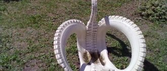
Gluing sandpaper to the disc
Gluing abrasive material to the hard drive disk is a simple but responsible job, since the disk rotates at a higher speed and the sandpaper may fall off.
I did not place an emery cloth under the ring pressing the disk, because the mounting screws were short and the reliability of fastening the disk could be reduced.
Therefore, the size of the internal hole was chosen slightly larger than the outer diameter of the ring holding the disk - 34 mm. The external size was equal to the disk diameter - 95 mm. The easiest way to apply markings is with a compass.
You can cut the outer contour of the sandpaper using scissors, and their cutting edges will also be sharpened. It’s easier to cut the internal hole with a construction knife.
For good adhesion of the hot-melt adhesive to the disk, you need to turn on the machine and remove the mirror surface by touching the surface of the rotating disk with sandpaper.
To glue sandpaper to a disk, you can use any suitable glue, for example, “Moment”. But I read that hot melt adhesive is good for these purposes and decided to try it.
Over time, the abrasive will wear off and the sandpaper will have to be peeled off to be replaced. If it holds tightly, it will create difficulties in separating the web from the disk. Just warm up the hot melt adhesive and the worn sheet will easily separate from the disc. I didn’t heat up the gun, but simply cut small pieces of hot-melt glue and spread them evenly on sandpaper.
Next, I placed a disk on top of the hot melt glue so as not to stain the iron on the cotton fabric, and on top of the iron, turned on in the maximum heating mode. Instead of fabric, a sheet of paper will do.
When the iron's heating indicator went out, I removed it and replaced it with a heavy, cold piece of iron. After a minute, the hot melt glue cooled and hardened.
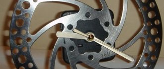
All that remains is to attach the grinding disc to the engine and you can get to work. I enjoyed working on the machine; I sharpened all the small tools and dull drills.
I bring to your attention a short video clip demonstrating a disc grinding and sharpening machine in operation.
If the steel is tool steel and hardened, then when sharpening and straightening the tool, a sheaf of sparks flies. Experienced mechanics even determine the grade of steel by the appearance and color of the sparks.
The homemade product turned out to be very useful and easy to use; it’s a pity that I didn’t make such a sharpening machine earlier. If you are a craftsman, I highly recommend making yourself such a machine.
Emery from a hard drive: possibilities of use. Necessary materials and tools. The process of disassembling a hard drive. Preparing the abrasive surface and assembling the mini-machine. Features of power connection and possible difficulties.
Using sandpaper from the hard drive of a personal computer, you can edit and sharpen hand tools, knives or small parts. The main advantage of the device: its manufacture requires a minimum amount of tools and auxiliary materials. In this case, the performance of the hard drive does not play a special role: its functions will be completely different.
Modern computer hard drives are not very well suited to realize the idea. The fact is that on HDDs of the first generations, magnetic circles were large in size. This allows you to expand the range of processed elements.
Installation and installation of electronic components
It's time to place the controller, switch and power supply connector in the hard drive case. After determining the installation locations for these elements, the case and controller had to be modified.
Since the height of the controller did not fit into the hard drive case, it had to be modified. An electrolytic capacitor with a capacity of 470 microfarads for a voltage of 16 V was positioned coaxially with the speed controller by increasing the length of the leads. The plastic case was removed from the connector and the pins were shortened to a height of 3 mm. The wires are connected to them by soldering. Instead of a jumper, a jumper made of copper wire is soldered.
Since it was impossible to reduce the height of the variable resistor of the speed controller, the hole in the housing, in which the adapter connector from the magnetic head was previously located, was bored out with a file so that the resistor and capacitor would fit into it. The controller was secured through the bushing with a screw.
The power switch was secured in a hole drilled for it on the side with a nut. The connector for connecting the cord from the power adapter was secured in the rear wall of the case using hot-melt adhesive. There is no point in describing in detail the technology for fastening electronic components, since hard drive cases are different and each specific case will require a different solution.