One of the effective ways to improve everyday comfort in the home is to switch from conventional to remote control of lights. In this case, the lighting turns on automatically for any event - opening a door, movement, a signal from a remote control or mobile phone, according to a timer, etc. Let’s look at what a remote lighting control system is, how it works and what tasks it allows to solve, what are its pros and cons, what options exist for use in a private home.
Programming parameters in the control unit allows you to automatically set the level of illumination depending on the time of day Source electrica.net.ua
Remote control device
A household remote control is a box with buttons on the front.
The remote control operates on batteries and sends signals in the form of infrared rays (0.75 - 1.4 microns). The wave is not recognized by a person, but is perceived by the receiving mechanism. The design contains a packaged or packaged microcircuit, which is located on a dielectric plate and filled with a polymer thermoplastic resin. The universal remote control panel has the following basic parts:
- power key, device selection;
- volume control and channel switching, date and time settings;
- numeric keys for entering numbers;
- programming buttons;
- joysticks for menu navigation;
- keys, the purpose of which is chosen by the user independently;
- LCD or touch screen showing current information.
Devices with many functions require a complex system with wave frequency regulation, which also protects the channel from interference and encodes the commands being sent. Digital conversion is used by the remote control chip and decoding by the receiver.
The difference between a universal remote control and the original ones
The following key differences can be identified between the universal and original TV remote control:
- The universal remote control has integrated commands for all common TV models. The original one works only with one set of signals programmed by the manufacturer.
- A universal remote control may not have the entire list of buttons that are available in the original one. Some manufacturers have provided this, so a number of functions can be activated using key combinations. We are talking only about rarely used commands, for example, switching equalizer settings. As a rule, the sound is adjusted only once, after which such a need does not arise.
- A universal remote control can be used to control not only a TV, but also a set-top box, DVD player, stereo system and even an air conditioner. The original one is only compatible with the TV for which it was released.
- Universal remote control from some manufacturers supports signal copying and “learning” mode. That is, you can assign any commands to it. This will allow, for example, to control other household appliances in the house that have an infrared sensor to receive the signal. But to set it up you need the original remote control.
The only advantage of the original remote controls is low battery consumption, as well as higher quality materials used in production (although there are also universal remote controls, the quality of which is not inferior at all).
Operating principle of the remote control
More often, devices use one frequency modulation (radiation from an LED element), to which the receiver and remote control are tuned. Frequency values with constant amplitude are usually unchanged - these are 36, 38 or 40 kHz (Button, Canon, Pro Black). 56 kHz indicators are rarely used (Sharp, Runva, Doorhan). Bang & Olufsen products operate at 455 kHz, which is a rare characteristic.
If the frequency of the receiver and transmitter do not match, the remote control will work, but its sensitivity will decrease. Several modulated bursts of pulses create a coded message, and the receiver contains a demodulator, a filter circuit, and a frequency detector.
Previously, only the basic commands of the controlled device were placed on the remote control; most of the controls were located on the body of the household appliance. The situation has changed: ventilation, gates, lighting, and traffic light equipment can only be controlled using a remote device.
D.C
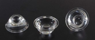
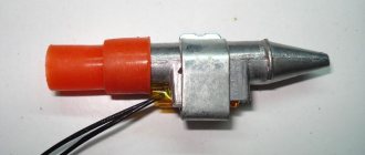
Optocoupler
An optocoupler is an excellent element that allows you to perform two functions: to switch a load (albeit a small one) and completely physically decouple the microcontroller from it. Optocouplers can be used to simulate pressing buttons on other external devices, that is, to close a purely logical signal. Can also be used to interrupt power supply to various sensors and modules in the device instead of a transistor. An optocoupler consists of two parts: an LED, which we turn on using a microcontroller, and an output part, which can be different (transistor, triac, etc.), thus the signal from the microcontroller is separated from the load through a beam of light , which is very important when switching high-voltage or some sensitive circuits. To control external devices, you need to take optocouplers with a transistor output , for example the very common PC814 and its analogues ( FOD814 , LTV814 and others), if desired, you can pick them out of almost any power supply. This optocoupler allows you to switch loads with voltages up to 60 Volts and currents up to 50 mA. I’ll show you a clipping from the datasheet with these parameters; for other optocouplers the parameters will be named exactly the same:
The optocoupler is connected in the following way: we control the LED from the MK through a resistor, and connect the output to the load break, observing the polarity. As for the LED at the control input of the optocoupler, it requires a resistor; how to calculate a resistor for an LED was described in the lesson about LEDs. In most cases, it is enough to install a 220 Ohm resistor, as for any LEDs. If the LED current is less than specified, the maximum output current will decrease accordingly, which is already critical for this optocoupler (the LED wants as much as 50 mA). The optocoupler is not designed to control a large load; usually it is switching other logical circuits, so you don’t have to think about the current. Load connection (conditional load resistor):
To control the “button” of another device (camera, coffee machine), just connect an optocoupler in parallel to the button. To avoid shorting the optocoupler to the button (which will burn the optocoupler), it is advisable to install a protective resistor with a nominal value of 200-1000 Ohms. There will be two schemes, essentially the same. Before connecting, you need to check with a multimeter where the “plus” button is and where the “minus” button is, since the output from the optocoupler is polar.
There is also an interesting optocoupler TLP172 with a mosfet output, and non-polar (it can switch the load in any direction)! Controls voltage up to 60 Volts at currents up to 400 mA - this is already quite a serious toy.
Transistor
The most compact way to drive a DC load is with a transistor. Transistors can be bipolar and field-effect (MOSFET, field switch, switch). Bipolar ones are already morally and physically obsolete, have many characteristics and require additional study of the topic, so we will consider only field-effect transistors. The diagram is typical and looks like this:
Or like this, specifically for the to220 case. Also in this diagram, the Arduino board is powered from an external source at the Vin pin:
Field switches also come in other packages; to connect according to the first circuit diagram, you need to google the pinout for your specific transistor. But basically it goes like this:
What kind of resistors are they?
- A 100 Ohm resistor (can be set in the range of 100-500 Ohms, any power ) performs a protective function: the field gate is a capacitor, at the moment the gate opens the capacitor will begin to charge and a large current will flow in the circuit (almost a short circuit), which can damage the pin Arduino. The resistor simply limits the current in the pin-gate circuit and saves the pin from current surges. In general, you don’t have to install it, but someday it will definitely break =)
- A 10 kOhm resistor (can be set in the range of 5-50 kOhm, any power ) performs a pull-up function for the gate. If it happens that the Arduino board is turned off or the signal wire from it falls off, random interference will come to the gate and it may accidentally open. If at this moment the power source is connected, the load will also turn on! The uprising of the machines will begin from this moment. A pull-up resistor to GND allows you to “press” the gate so that it does not open on its own. It makes sense to place it directly on the transistor body if the installation is carried out in a canopy:
I have provided a circuit that uses an N-channel field-effect transistor that controls the GND line. There are also P-channel mosfets, they control the power line. Such transistors are generally more expensive, less common and have a high threshold voltage, i.e. for them to work, you will have to install another transistor (bipolar) and use it to supply a higher signal from an external source to the gate of the P-channel field switch. Therefore, in 99% of cases they simply use more convenient N-channel keys. How to choose a transistor for your task? First of all, we look at the opening voltage of the transistor (how to read the graph in the datasheet - see the video lesson below), a transistor marked Logic Level in the description or datasheet is 100% suitable: such mosfets will definitely work to the fullest from the MK pin. Of course, the current and voltage must correspond (taken with a margin) for the load that the mosfet will switch. There is also a parameter, the resistance of the open channel, at this resistance the voltage will drop and turn into heat. For powerful loads, you need to consider field switches with low channel resistance so that they do not get too hot. I will give my list of mosfets in two main packages: output to220 and dpack for surface mounting, in it “ Current at 3V ” and “ Current at 5V ” means the maximum current through the transistor (to the load) in Amperes when controlling a logic signal of 3 and 5 Volts. See the maximum voltage for the load for a specific transistor, but for all of them it is higher than 24V. “ R ” is the open channel resistance in milliohms (10^-3 Ohms). Also, field crops are sorted by increasing prices in Russian stores =)
Housing to220
| Marking | R, mOhm | Current at 3V | Current at 5V |
| IRLZ24NPBF | 60 | 4 | 20 |
| IRF3704ZPBF | 7.9 | 10 | >100 |
| IRLB8743PBF | 3.2 | 20 | >100 |
| IRL2203NPBF | 7 | 30 | >100 |
| IRLB8748PBF | 4.8 | 10 | >100 |
| IRL8113PBF | 6 | 40 | >100 |
| IRL3803PBF | 6 | 20 | >100 |
| IRLB3813PBF | 1.95 | 20 | >100 |
| IRL3502PBF | 7 | >100 | >100 |
| IRL2505PBF | 8 | 20 | >100 |
| IRF3711PBF | 6 | 80 | >100 |
| IRL3713PBF | 3 | 20 | >100 |
| IRF3709ZPBF | 6.3 | 40 | >100 |
| AUIRL3705N | 6.5 | 20 | >100 |
| IRLB3034PBF | 1.7 | >100 | >100 |
| IRF3711ZPBF | 6 | 20 | >100 |
dpak housing
| Marking | R, mOhm | Current at 3V | Current at 5V |
| STD17NF03LT4 | 50 | 5 | 40 |
| IRLR024NPBF | 65 | 4 | 20 |
| IRLR024NPBF | 40 | 5 | 40 |
| IRLR8726PBF | 6 | 10 | 110 |
| IRFR1205PBF | 27 | – | 10 |
| IRFR4105PBF | 45 | – | 10 |
| IRLR7807ZPBF | 12 | 10 | 100 |
| IRFR024NPBF | 75 | – | 8 |
| IRLR7821TRPBF | 10 | 11 | 100 |
| STD60N3LH5 | 8 | 30 | 160 |
| IRLR3103TRPBF | 19 | 11 | 100 |
| IRLR8113TRPBF | 6 | 40 | 110 |
| IRLR8256PBF | 6 | 10 | 110 |
| IRLR2905ZPBF | 13 | – | 100 |
| IRLR2905PBF | 27 | 20 | 90 |
For low-current circuits, I like to use a 2n7000 (buy a bag) - it pulls up to 400 mA. The case is a compact output to-92. Also, our Chinese friends have convenient ready-made modules with mosfets and all the necessary wiring:
Well, the most important point: you can apply a PWM signal to the field-effect transistor for “smooth” load control: smoothly change the motor rotation speed, the brightness of the LED strip, the heater power, and so on!
Attention! When controlling an inductive load (valve, motor, electromagnet, solenoid), a diode is required! See last chapter.
Solid State Relay (SSR DC)
A simpler option is a solid state relay (Solid State Relay, SSR) for direct current (DC), which can be found on Aliexpress at the request SSR DC. VDC should be written under the output terminals , i.e. constant pressure. The solid state relay has a standard housing for both DC and AC models, so you need to read what is written and not confuse it. Also in the marking after the word SSR the current is usually indicated in Amperes, i.e. The SSR-25 is a 25 Amp relay. The maximum voltage is indicated below the output terminals.
The solid state relay is connected directly to the Arduino, pin “-” to GND, “+” to any digital pin. The relay output is placed in the open circuit of the load power supply, like a switch. It is important not to confuse plus and minus, because inside the relay is a field-effect transistor on a radiator =)
Attention! When controlling an inductive load (valve, motor, electromagnet, solenoid), a diode is required! See last chapter.
Types of wireless remote controls
Built-in remote control
The devices are powered by 2 - 4 removable batteries of type AA, AAA, less commonly used 9 V Krona batteries. The IR LED requires 2.5 volts to operate, so several elements are required to ensure the remote control level. Experts recommend alkaline or salt batteries.
Depending on the type of power supply, there are remote controls:
- autonomous;
- devices powered from a 220 V electrical network or with a 360 V converter.
They produce portable devices that are often used in everyday life for wireless control of lamps, chandeliers, gate opening, tail lift operation, and other switches. The built-in IR remote control is installed to control complex smart home systems or installed in industrial complexes to control, for example, a crane.
Control devices are classified according to functionality:
- with a limited number of teams;
- with a choice of the number of orders (universal option, for example brand ABCD);
- with the ability to train a set of signals (trainable models, for example, DC V).
ABCD remote control
DC V remote control
Communication with the controlled equipment is established mechanically or wired, using a radio channel, WI-FI, ultrasonic and infrared methods. The Trodfrey driver controls the light in a home remote control, and Wireless USB replaces standard wired transmissions.
Smart home equipment for apartments: light control via the Internet
The availability of this method is based on the fact that the remote lighting control scheme is based on the use of devices that already work in most of our apartments.
State-owned information technology companies have long provided most residents with unlimited Internet that operates around the clock.
I purchased smart home equipment for an apartment in China from Sonoff. Next I show how the remote lighting control scheme works via the Internet from a smartphone.
The kit includes a Sonoff smart switch and a small key fob remote control.
In principle, all work via the Internet occurs through a smartphone, and the remote control is only needed to switch the lights inside the apartment. Although even in this case you can get by with your mobile phone.
It’s just convenient to keep the key fob remote control in one place; all family members, including children, can use it. In addition, it works regardless of the presence of WiFi.
Now I do not intend to fully describe the settings of the smartphone and the connection of its circuit to the smart switch, but will focus on the difficulty that I had to face when installing the module in the old installation box.
My apartment is located in a multi-storey panel building built in Soviet times. For electrical wiring, the factory immediately created channels for laying cables.
They are located at arbitrary angles, often in the most inconvenient places for installation: literally in the recess at the junction of the wall and the ceiling slab. A channel for switches or socket groups runs downwards from it obliquely.
The old switch connection diagram is based on breaking only the phase wire. Therefore, the zero potential is not drawn there.
However, a Sonoff smart switch without zero potential will not work. I had to pull it there through an inclined channel.
When I removed the old switch housing, I saw an ordinary aluminum noodle - 2 wires. Then he climbed into the junction box, if that’s what you can call the place where the slabs join, which was covered with small gravel with scraps of newspapers and pieces of concrete.
I saw a tangle of twisted wires and black electrical tape. The voltage indicator and digital multimeter helped quickly understand the purpose of each connection.
It turned out to be a problem to insert an additional core of zero potential. The crushed stone and cement dust firmly filled the entire space of the cable channel.
Even attempts to pass through this composition with a rigid steel wire were unsuccessful. And inside the room, cosmetic work was recently carried out and new wallpaper was installed. I didn't want to stir up any dirt.
I used the old trick:
- Turned off the light in the apartment panel.
- I taped a piece of copper cable with three cores to the lower end of the old two-core wire with strong electrical tape.
- I inserted pliers with long jaws into the ceiling cavity and clamped them with the top piece of aluminum noodles, because it is impossible to pull it there with your fingers.
- I began to little by little wind the wire onto the pliers and remove the debris that was coming out of the channel, afraid that it would break. But it worked out.
In this way, it was possible to pull a new cable through the littered main and remove several handfuls of small stones from it. Why were they put there? I don't have an answer to this question.
I hope that my experience will be useful to someone.
By the way, much of the equipment from Nootekhnika: Belarus also allows you to control the light remotely via the Internet from mobile devices in the same way.
Remote control diagram
An encoding method is used to distinguish the commands of the transmitting block. Before broadcasting the signal, the remote control issues one or more synchronous packets so that the touch receiver sets up the receiving circuit and synchronizes with the transmitter in phase and degree of sensitivity.
Two schemes have been developed for this purpose:
- The first system is used in the Philips remote control (in accordance with the RC5 and RC4 protocols). The sending of signal 0 is supplemented by the number 1, and sending 1 requires the addition of 0. Signal 001 arrives in the form of 010110 and is read sequentially, and a simulated packet is sent into space.
- The authors of the second encoding scheme are representatives of Sony. One is transmitted in a modulated burst, and zero means a pause. Zero transmits encoded information at the same time indicator of one.
Studies have shown that the duration of signals varies by time deviations at the level of +-10%. Transmitted packets are modulated by changing the frequency, which affects the operating range of the device.
Radio-controlled switch for lighting devices: 2 tested circuits
RF switches use the principle of transmitting a command after pressing a certain button on the remote control and receiving a high-frequency signal by the receiver, followed by its processing by the microcontroller.
There is an opinion among ordinary people that the radio channel is harmful to health and is difficult to use. There is nothing complicated or dangerous in this matter. Now toys are being produced even for young children: cars, tanks and helicopters that use this technology.
In addition, the radio-controlled switch only works for a short time. The designs I have tried are:
- butterfly chandelier;
- light switch Nootekhnika: Belarus.
Lighting control via radio channel: LED chandelier for a children's room
The lamp has a rather original device that provides the creation of beautiful lighting effects when remotely controlled from a remote control or from a simple switch.
A large collection of photographs of her work is shown in a separate article on my blog. Look there if anyone is interested.
The Elektrostandard remote control used has only four control buttons, designated in Latin letters A÷D.
The first three buttons remotely control the operation of individual lighting channels, and the fourth is used to generally turn the chandelier on or off.
For some reason, my LED butterfly chandelier broke after intensive use: its remote control from the remote control via the radio channel disappeared, but it worked from the switch.
In the picture below I show what the circuit of a chandelier with an LED control panel looks like in my case.
Its operation via a radio frequency channel is carried out by the remote control transmitter and the receiver built into the controller.
Their joint use requires the creation of a single remote control kit for each lighting fixture, which is what manufacturers do.
For repairs, I had to buy this Elektrostandard kit, consisting of a remote control, a controller and a regular AA battery.
Its low cost made it possible to perform a simple repair by simply replacing the controller inside the chandelier, eliminating the need for separate testing of the transmitter and receiver.
Finding such a malfunction is a technically complex matter. It requires good measuring equipment and electronics skills.
Having an ordinary digital multimeter in your hands and understanding how to use it correctly, it is not always possible to eliminate such a breakdown.
On sale, you will not be able to purchase a remote control with a transmitter or a controller with a receiver separately, and if you take them from different kits, even from the same batch of the same manufacturer, they will not work together.
I explain this by the fact that at the factory, each transmitter with its receiver is configured and encoded for individual operation using unique algorithms, and then the prepared equipment is assembled in pairs even before pre-sale preparation.
Be sure to take this feature into account. Understanding it will simplify your actions and reduce the time it takes to eliminate future breakdowns if they occur accidentally.
The frequency range at which such radio frequency modules operate is 300÷800 MHz, and the power of the radio transmitter cannot exceed 10 milliwatts. These parameters are regulated.
My kit is designed to work at a distance of 8 meters, which is more than enough for an ordinary apartment. However, this is far from the limit of the operation of such devices.
It is not difficult to find kits on sale that allow remote control of lighting devices via radio, up to 100 meters away in open areas.
If there are building structures in the path of the signal that reduce its power, then the distance can be reduced by four times. Therefore, local radio wave conditions must be taken into account when choosing the range of the control scheme.
Another important point: if you look carefully at the diagram of my chandelier again, you will notice that the controller itself is supplied with a phase with a working zero and a protective PE conductor.
Its phase potential is taken from the switch of an old chandelier, and the neutral and PE conductor are made by continuous installation from the apartment panel.
The switch key switches supply or remove voltage to the controller, and it turns the chandelier on or off, creating various lighting and color effects.
Our neighborhood maintains normal power supply. When frequent emergency power outages occur, such a scheme can cause trouble: when the lamp is on and the voltage goes out, you will need to turn off the switch.
If this is not done, the chandelier will turn on spontaneously when the power supply is restored: it will wake up the residents at night, and during the day it will disrupt the economy mode.
Some designs of light switches with radio remote control use a controller that is not located inside the lamp, but separately.
It can be built into the mounting box of a regular wall switch, next to the distribution box under a suspended or suspended ceiling. The only operating condition is the presence of phase and zero circuits.
However, you should not forget about the possibility of convenient access to it for preventive maintenance, inspection and repair.
Radio-controlled light switch Nootekhnika: Belarus - design features
The operating principles of this scheme practically repeat the previous algorithms, but the design of the devices differs in its range and capabilities.
The Belarusian manufacturer produces:
- actuator in the form of: controller SD-3-60 for 3 channels of LED lamps or another more powerful module;
- or ready-made switches for radio control;
- touch or push-button remote controls with a frame for permanent installation;
The design of various executive units is created for reliable switching of luminaire loads from 60 VA to 3 kW.
They are also capable of controlling other equipment with resistive or inductive loads, various types of drives and motors.
The range of the radio channel has been increased to 50 meters. The range of manufactured equipment is very wide.
It is convenient to mount a push-button or touch remote control anywhere on the wall directly onto decorative wallpaper. To do this, just use double-sided tape. There is no need to perform any dirty or labor-intensive work.
However, these modules cannot be glued to metal surfaces, such as the wall of a refrigerator. This will limit the range of the device by weakening the antenna output power.
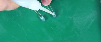
How to make a remote control with your own hands
4-channel remote control circuit
The remote control is a device that can be assembled by converting a smartphone. You need to purchase infrared diodes or remove them from unnecessary remote controls (2 pieces) and a plug from old headphones. For assembly you will need sandpaper, electrical tape and superglue; the work is carried out with wire cutters and a soldering iron.
The following steps are performed for manufacturing:
- On one side, the elements of the IR diodes protruding from the sides are cleaned using sandpaper.
- The diodes are connected using superglue so that the ground side is inside.
- The legs of the diodes need to be bent and the excess protrusions removed with pliers.
- The anodes are soldered to each other using a soldering iron.
- Similar processing of the second diode is carried out;
- Both LEDs must be connected to the plug lugs without observing polarity.
- The soldering area is coated with glue and protected with insulating tape.
The connection mode is done via IR Port or WI-FI, IR Blaster. The TV modification is selected and the action is confirmed. The converted smartphone is sent to the IR receiver of the home screen, and the functions are controlled.
Scope of use of remote control
A universal remote control controls several types of consumer electronics. Such a device differs from a local device, which is sold together with a washing machine, X-box or camera. UP is sold as a separate product and purchased separately.
Different manufacturing technologies affect the final actions of the device and its cost. Remote controls control one or more units, the range of application is determined by the manufacturer. Trainable models make it possible to specify a list of coordinated equipment through programming.
In everyday life, the IR remote control works with all modern models of household appliances, is used in a complex home automation system for climate control, organizing burglary protection, opens and closes entrance openings, and adjusts the operating mode of cooking and heating units.
Universal remote control app on your smartphone
The mobile phone can also be used as a remote control.
You just need to figure out how this or that TV receives commands:
- The most modern TVs have both an infrared receiver and a Bluetooth module. Therefore, you can control the TV with almost any smartphone.
- Old TVs only have an infrared receiver. Therefore, such a TV can only be controlled by a smartphone that has an infrared sensor. Now it is installed in most phone models from Xiaomi.
Also, to use your smartphone as a remote control, you will need to install a special application. For example, Mi Remote (the program was released for Xiaomi phones, but also works fine with other brands).
Apple smartphones have never had an infrared sensor installed. Therefore, they can only be used for remote control with a Bluetooth connection. And the list of compatible equipment is quite small. Normally, the iPhone is only suitable for controlling the branded AppleTV set-top box.
PDAs running Windows Mobile CE (common before 2010) are also often equipped with an IrDA sensor. And it is suitable not only for sending, but also for copying commands. Therefore, if someone still has such devices, they can easily be converted to a universal remote control. In modern Xiaomi, the built-in infrared sensors do not support reading commands. Therefore programming is not available.
How to set up the program
To set up Mi Remote (the principle is similar in other applications with similar functionality) you will need:
- Launch the application.
- Select "Add remote control".
- Specify the type of equipment (TV).
- Select the TV manufacturer from the list provided.
- Point the smartphone towards the TV, press the virtual “POWER” button.
- Press the key every 2-3 seconds until the TV turns on/off. After that, select “Save” and enter a name for the remote control.
Advantages of remote controls
The transition to remote control provides convenience for the user, since there is no need to move around the home to turn on the lights and set the microclimate parameters in the room. In an automated system, a person can use a remote control to ensure high-quality work at home without leaving his seat.
Remote response works successfully when objects are remote from the operator, for example, when coordinating aircraft, airplanes, and cars. Beacons, repeaters, and radio communication stations are controlled at a distance and do not require the direct presence of a person.
Games like Xbox previously used a wired communication system, but the change to wireless remotes gives players more options.