Operating principle of LED device
The basis of the LED lamp is a single-sided semiconductor, the size of which is several millimeters. There is a unidirectional movement of electrons in it, which allows you to convert alternating current into direct current.
An LED crystal consisting of several layers is characterized by two types of electrical conductivity: positively and negatively charged particles.
The side containing the minimum number of electrons is called hole (p-type), while the other with a large number of these particles is called electron (n-type).
Between the two sides of the LED element there is a conventional boundary - an electron-hole junction (pn). Here the particles collide with each other, resulting in a glow.
When elements at a pn junction collide, they collide, generating light particles called photons. If you keep the system at a constant voltage during this time, the LED will emit a stable stream of light. This effect is used in all LED lamp designs.
What is LED
LED technologies represent the conversion of current into light emission. For those who decide to make an LED device, the information provided below will not be useless.
An LED is a semiconductor located in a lens. When an electric current passes through it, it begins to glow.
Today there are a lot of different LEDs on the sales market, but nevertheless they are divided into only two groups - indicator and lighting.
In case of self-production or repair, it is necessary to focus on the labeling of LEDs.
- SMD - This type is used in LED products for lighting and backlighting.
- “Piranha” - used in advertising and auto lighting.
- COB - for ceiling devices.
- DIP - have low lighting intensity.
- Straw Hat - Defined as an incandescent light bulb.
To accurately select the necessary elements you need to know its technical parameters:
- The electricity consumption in most cases is 20 mA;
- Voltage according to color - red 1.5 - 2.6V, green - 1.7 - 4.0V, yellow - 1.7 - 2.5V, orange - 1.7 - 2.8V;
- Power dissipation - this parameter determines the type of power supply for the required number of LEDs;
- Angle of illumination - this parameter looks like this - lighting - larger, indicator - correspondingly smaller.
- Glow temperature - its designation can be seen on the packages. Warm light 2700 - 3000K, neutral - 3500 - 4000K, cool glow - 5700 - 7000K.
The operating period before the onset of aging may not correspond to the established one and depends on proper use.
Four types of LED devices
Depending on the placement of LEDs, such models can be divided into the following categories:
- DIP . The crystal is arranged with two conductors, above which there is an enlarger. The modification has become widespread in the manufacture of signs and garlands.
- "Piranha" . The devices are assembled similarly to the previous version, but have four outputs. Reliable and durable structures are most often used to equip cars.
- SMD . The crystal is placed on top, which significantly improves heat dissipation and also helps reduce the size of the devices.
- OWL . In this case, the LED is soldered directly into the board, which increases the glow intensity and protects against overheating.
A significant disadvantage of COB devices is the impossibility of replacing individual elements, which is why you have to purchase a new mechanism due to a single failed chip.
Chandeliers and other household lighting products typically use SMD design.
Finalization of the finished LED flashlight
In some cases, it is easier to buy an inexpensive ready-made LED flashlight and, with the help of small improvements, make a more advanced model.
For example, in the HG-528 HUAGE device and flashlights similar in circuit design, diodes EL1-EL5 often fail. The problem arises because owners often forget to disconnect semiconductor elements when charging from the mains.
You can modify your flashlight so that it will be impossible to charge unless you change the position of the SA1 switch so as to turn off the LEDs. In addition, the short-lived batteries of these devices can be replaced with more energy-intensive lithium-ion devices from mobile phones. Why are rectifier diodes VD1-VD4 and a filter consisting of capacitance C1 and two resistors R1, R2 removed from the flashlight?
After a small cutting of the plastic parts of the case, a cell phone battery is placed in the vacant space. The latter is connected with a copper wire to the device circuit.
The developers of the Lentel GL01 LED rechargeable flashlight made an error in the electrical circuit, which also leads to failure of the device if it is turned on for charging when the LEDs are not turned off. In addition, 7 diodes are connected in parallel, which causes uneven current flowing through them during operation of the flashlight due to the different current-voltage characteristics of the semiconductor elements. This leads to frequent burnout of both the LEDs themselves and resistor R4.
If individual resistors (45 - 55 Ohms) are connected in series with each LED, and resistor R4 is removed from the circuit, then the current values will be equalized. To prevent voltage from reaching the LEDs of the charger while charging the battery, you need to connect HL1 (indicator) to the first pin of SA1.
LED lamp device
The LED lamp consists of the following six parts:
- Light-emitting diode;
- base;
- driver;
- diffuser;
- radiator.
The operating element of such a device is an LED, which generates a stream of light waves.
LED devices can be designed for different voltages. The most in demand are small products of 12-15 W and larger lamps of 50 watt.
The base, which can have different shapes and sizes, is also used for other types of lamps - fluorescent, halogen, incandescent. At the same time, some LED devices, for example, LED strips, can do without this part.
An important design element is the driver, which converts the mains voltage into the current on which the crystal operates.
The efficient operation of the lamp largely depends on this unit; in addition, a high-quality driver with good galvanic isolation provides a bright, constant luminous flux without a hint of blinking.
A conventional LED produces a directional beam of light. To change the angle of its distribution and provide high-quality lighting, a diffuser is used. Another function of this component is to protect the circuit from mechanical and natural influences.
The radiator is designed to remove heat, excess of which can damage the device. Reliable operation of the radiator allows you to optimize the operation of the lamp and extend its life.
The smaller this part, the greater the thermal load the LED will have to withstand, which will affect the speed of its burnout.
Main components
The design of an LED flashlight will consist of the same components, regardless of whether it is homemade or manufactured in a factory. An important requirement for him will be mobility, i.e. it should be a rechargeable flashlight with charging from a 220 V network (the simplest and most affordable option), or from a USB computer or laptop. This method allows you to recharge the LED device in the field, which is very important when camping.
The main components and parts of such a device:
- powerful LED or matrix;
- radiator for heat removal;
- battery;
- charging module;
- reflector with lens;
- frame.
Most parts cannot be made by hand. Usually they use ready-made units purchased specifically for such a case or taken from broken devices. The only option that allows for a creative approach is the flashlight body, since it can be made from various donor parts.
Advantages and disadvantages of a homemade lamp
Specialized stores offer a large selection of LED devices. However, sometimes it is impossible to find a device in the assortment that meets the necessary parameters. In addition, LED devices are traditionally high in cost.
Disadvantages of the products include the lack of a warranty from the manufacturer. In addition, if assembled carelessly, such devices may have an unattractive appearance.
Meanwhile, it is quite possible to save money and get the perfect lamp by assembling it yourself. This is not difficult to do and basic technical knowledge and practical skills will be enough.
A DIY LED device has a number of significant advantages over a store-bought analogue. They are economical: with careful assembly and the use of high-quality parts, the service life reaches 100 thousand hours.
Such devices show a high degree of energy efficiency, which is determined by the ratio of power consumption and the brightness of the light produced. Finally, their cost is an order of magnitude lower than their factory counterparts.
Advantages of LED lamps
LED lighting elements are displacing conventional incandescent lamps from the market. This is due to a number of advantages of LED technology:
- The emission of light in semiconductors occurs more intensely. They are 8 times brighter than incandescent lamps, and also work better than sodium or energy-saving devices.
- Due to their high efficiency compared to common light bulbs, LEDs can save from 60 to 90% of electricity. LED devices consume less resources than energy-saving devices (by 15-20%).
- The maintenance cost of semiconductors is lower because they have few failures and failures. LEDs are used in difficult operating conditions - for emergency systems, on high-rise architectural objects, in structures with expensive installation, in bridge lighting.
- New devices are installed quickly, with considerable savings in cable costs, which in semiconductors require a smaller diameter.
- Service life of LED devices: more than 15 years when operating 8 hours a day.
- Low voltage is used to power LEDs. This makes their installation and operation safer than equipment designed for 220/380 V.
- Semiconductors have good resistance to vibration, increased mechanical strength, and high temperature characteristics.
- The color rendering index of semiconductor devices exceeds 80. Without wasting energy or using filters, the devices are able to provide deep and pure colors of light.
- LED devices are suitable for timers, volume sensors, dimmers (light intensity regulators). LEDs are widely used in programmable equipment with variable lighting intensity.
- There are no ultraviolet and infrared radiation in diode products, the light is monochromatic, there is no strobing or glare. This allows them to be used in lighting systems of various purposes, sizes and shapes.
- LEDs have a minimum start-up time. Even in frosty weather, the device instantly reaches the color temperature and the specified light level.
- Due to the absence of harmful radiation and heat, semiconductors can be safely used for medical purposes, as well as for lighting rooms with people, animals and plants.
- The devices are recycled after their intended service life without producing environmentally hazardous substances.
DIY problems
The main issues that have to be resolved in the manufacture of LED lamps are the conversion of alternating electric current into pulsating and its equalization to constant. In addition, it is necessary to limit the power flow to 12 volts, which is necessary to power the diode.
To create an LED lamp yourself, you can use parts purchased in specialized stores, or elements from burnt-out appliances
When thinking through the device, you should also solve a number of design problems, namely:
- how to arrange the circuit and LEDs;
- how to isolate the system;
- how to ensure heat exchange in the device.
Before assembly, it is advisable to think through all these problems, taking into account the requirements for a homemade light source.
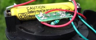
Battery
To power the flashlight, I decided to use battery cells from a “dead” screwdriver battery. I took all 10 elements out of the case. The screwdriver ran on this battery for 5-10 minutes and died, according to my version, the elements of this battery may well be suitable for operating the flashlight. After all, a flashlight requires much lower currents than a screwdriver.
I immediately unhooked three elements from the common connection, they will just produce a voltage of 3.6 volts.
I measured the voltage on each element separately - all of them were about 1.1 V, only one showed 0. Apparently this is a faulty can, it’s in the trash. The rest will still serve. For my LED assembly, three cans will be enough.
After scouring the Internet, I discovered important information about nickel-cadmium batteries: the nominal voltage of each element is 1.2 volts, the bank should be charged to a voltage of 1.4 volts (voltage on the bank without load), discharged should be no lower than 0.9 volts - if several elements are stacked in series, then not lower than 1 volt per element. You can charge with a current of a tenth of the capacity (in my case 1.2A/h = 0.12A), but in fact it can be higher (the screwdriver charges for no more than an hour, which means the charging current is at least 1.2A). For training/recovery, it is useful to discharge the battery to 1 V with some load and charge it again several times. At the same time, estimate the approximate operating time of the flashlight.
So, for three elements connected in series, the parameters are as follows: charging voltage 1.4X3 = 4.2 volts, nominal voltage 1.2X3 = 3.6 volts, charging current - what will the mobile charger with the stabilizer of my manufacture give.
The only unclear point is how to measure the minimum voltage on discharged batteries. Before connecting my lamp, the voltage on the three elements was 3.5 volts, when connected it was 2.8 volts, the voltage quickly restored when disconnected again to 3.5 volts. I decided this: with a load the voltage should not fall below 2.7 volts (0.9 V per element), without a load it is desirable that it be 3 volts (1 V per element). However, it will take a long time to discharge; the longer you discharge, the more stable the voltage will be, and it will stop dropping quickly when the LEDs are lit!
I discharged my already discharged batteries for several hours, sometimes turning off the lamp for a few minutes. The result was 2.71 V with the lamp connected and 3.45 V without load; I did not dare to discharge further. I note that the LEDs continued to shine, albeit dimly.
LED lamp circuits
First of all, you should develop an assembly option. There are two main methods, each of which has its own pros and cons. Below we will look at them in more detail.
Option with diode bridge
The circuit includes four diodes that are connected in different directions. Thanks to this, the bridge acquires the ability to transform the mains current of 220 V into a pulsating one.
The LED bridge circuit is simple and logical. Even a novice master who has mastered the basics of independent work can perform it.
This happens as follows: when sinusoidal half-waves pass through two diodes, they change, which causes a loss of polarity.
During assembly, a capacitor is connected to the positive output in front of the bridge; in front of the negative terminal - a resistance of 100 Ohms. Another capacitor is installed behind the bridge: it will be needed to smooth out voltage drops.
Making an LED element
The easiest way to create an LED lamp is to make a light source based on a broken lamp. It is necessary to check the functionality of the detected parts, which can be done using a 12 V battery.
Defective elements must be replaced. To do this, you should unsolder the contacts, remove the burnt out elements, and put new ones in their place. In this case, it is important to observe the alternation of anodes and cathodes, which are attached in series.
If you need to change only 2-3 pieces of the chip, you can simply solder them to the areas where the failed components were previously located.
For complete self-assembly, you need to connect 10 diodes in a row, observing the polarity rules. Several completed circuits are soldered to the wires.
When making a lamp, you can use boards with LEDs, which can be found in burnt-out devices. It is only important to check their functionality
When assembling circuits, it is important to ensure that the soldered ends do not touch each other, as this can lead to a short circuit in the device and failure of the system.
Devices for softer light
To avoid the flickering characteristic of LED lamps, the circuit described above can be supplemented with several details. Thus, it should consist of a diode bridge, 100 and 230 Ohm resistors, 400 nF and 10 μF capacitors.
To protect the device from voltage surges, a 100 Ohm resistor is placed at the beginning of the circuit, followed by a 400 nF capacitor, after which a diode bridge and another 230 Ohm resistor are installed, followed by an assembled chain of LEDs.
Resistor devices
A similar scheme is also quite accessible to a novice master. To do this, you need two 12k resistors and two chains of the same number of LEDs, which are soldered in series, taking into account the polarity. In this case, one strip on the R1 side is connected to the cathode, and the other to R2, the anode.
Lamps made according to this scheme have a softer light, since the operating elements are lit in turn, making the pulsation of the flashes almost invisible to the naked eye.
To calculate the lamp power, you need to know the amount of current that passes through the LEDs. This value can be calculated using the given formula. It should be taken into account that the voltage drop in 12 LEDs connected in series is approximately 36V
The devices are successfully used as a table lamp and for other purposes. To create optimal lighting, experts recommend using strips of 20-40 diodes. A smaller number gives a small luminous flux; connecting a larger number of elements is technically quite difficult.
Charger for nickel-cadmium batteries
Now you need to build a charger for the flashlight. The main requirement is that the output voltage should not exceed 4.2 V.
If you plan to power the charger from any source of more than 6 volts, a simple circuit based on KR142EN12A is relevant; this is a very common microcircuit for regulated, stabilized power. Foreign analogue of LM317. Here is a diagram of the charger on this chip:
But this scheme did not fit into my idea - versatility and maximum convenience for charging. After all, for this device you will need to make a transformer with a rectifier or use a ready-made power supply. I decided to make it possible to charge the batteries from a mobile phone charger and a computer USB port. To implement it, you will need a more complicated circuit:
The field-effect transistor for this circuit can be taken from a faulty motherboard and other computer peripherals; I cut it off an old video card. There are plenty of such transistors on the motherboard near the processor and not only. To be sure of your choice, you need to enter the transistor number into the search and make sure from the datasheets that it is a field effect one with an N-channel.
I used the TL431 microcircuit as a zener diode; it is found in almost every mobile phone charger or other switching power supplies. The pins of this microcircuit must be connected as in the figure:
I assembled the circuit on a piece of PCB and provided a USB socket for connection. In addition to the circuit, I soldered one LED near the socket to indicate charging (that voltage is being supplied to the USB port).
A few explanations about the diagram
Since the charging circuit will always be connected to the battery, the VD2 diode is necessary so that the battery does not discharge through the stabilizer elements. By selecting R4, you need to achieve a voltage of 4.4 V at the specified test point, you need to measure with the battery disconnected, 0.2 volts is the reserve for drawdown. And in general, 4.4 V does not exceed the recommended voltage for three battery cells.
The charger circuit can be significantly simplified, but you will only have to charge from a 5 V source (the computer’s USB port meets this requirement); if the phone charger produces a higher voltage, it cannot be used. According to a simplified scheme, theoretically, batteries can be recharged; in practice, this is how batteries are charged in many factory products.
Important element: LED driver
For the correct operation of a DIY LED device, you need to resolve the issue with the driver. The layout of this unit is quite simple. The operating algorithm consists of passing an alternating current of 220V to the diode bridge through capacitor C1.
The rectified current goes to series-connected LEDs HL1-HL27, the number of which can reach 80 pieces.
The driver for a homemade LED device is assembled according to the diagram below. You can also use ready-made elements bp 3122, bp 2832a or bp 2831a
To avoid flickering and achieve a consistently even color, it is advisable to use capacitor C2, which should have as large a capacity as possible.
How to assemble it yourself
When assembling the circuit, we will need a transformer, but it was not added to the list. We will make it ourselves from a ferrite ring and wire. This is very simple to do, take our ring and start winding the wire forty-five times, this wire will connect to the LED. We take the next wire, wind it thirty times already, and direct it to the base of the transistor.
The resistor used in the circuit should have a resistance of 2000 ohms, only by using such resistance can the circuit work without failure. When testing the circuit, replace resistor R1 with a similar one with adjustable resistance. Turn on the entire circuit and adjust the resistance of this resistor, adjust the voltage to approximately 25mA.
As a result, you will know what resistance should be at this point, and you will be able to select a suitable resistor with the resistance value you need.
If the circuit is drawn up in full accordance with the above requirements, then the flashlight should work immediately. If it doesn't work, then you may have made the following mistake:
- The ends of the winding are connected in reverse.
- The number of turns does not correspond to what is required.
- If the wound turns are less than 15, then current generation in the transformer ceases.
Housings for LED devices
Before assembly, it is important to decide where the assembled circuit will be placed.
There are several options for solving this problem - to place the device you can use:
- incandescent lamp bases;
- housings from burnt-out energy-saving or halogen lamps;
- hand-made devices.
The first option has an important advantage. When using it, it is easy to screw the assembled LED device into the socket, thereby ensuring heat exchange.
It should be noted that in addition to the obvious advantages, this method also has obvious disadvantages. The assembled structure does not have a very aesthetic appearance; in addition, in this case it is difficult to provide reliable insulation.
In order to use a burnt-out incandescent lamp to create an LED one, you must first carefully separate the glass bulb from the base and then remove the spiral. The assembled circuit is carefully placed in the resulting space, and a light bulb is fixed above the board.
A convenient and practical option is to place a homemade device in the body of an energy-saving lamp. To do this, you first need to disassemble the burnt-out device by removing the converter board from it.
The assembled diagram can be inserted using different methods:
- The diodes are placed in holes made in the lid under the glass bulb.
- The circuit can be placed inside the base, which guarantees heat exchange. In this case, LED elements are inserted and fixed into existing holes.
- The board can be hidden in the base. To carry out the process, it is convenient to use a regular plastic cap from a water bottle.
To place LEDs, craftsmen often use a hand-made circle of plastic or cardboard, in which holes are drilled for the diodes. When done carefully, such devices look quite aesthetically pleasing.
Another option is to use a halogen lamp housing. It is not widely used, since in this case it is not possible to screw the lamp into the socket. Nevertheless, a similar modification is used to make homemade indicators and other devices.
If you decide to use a light bulb body for your work, we recommend reading our other article, where we described in detail how to disassemble various types of light bulbs. For more details, follow the link.
Necessary components
If you decide to assemble an LED flashlight with your own hands, for moving in the dark or for working at night, but don’t know where to start? We will help you with this. The first thing you need to do is find the necessary elements for assembly.
Here is a preliminary list of required parts:
- Light-emitting diode
- Winding wire, 20-30 cm.
- The ferrite ring is approximately 1-.1.5 cm in diameter.
- Transistor.
- 1000 ohm resistor.
Of course, this list needs to be supplemented with a battery, but this is an element that can be easily found in any home and does not require special preparation. You should also select a housing or some kind of base on which the entire circuit will be installed. A good case would be an old, non-working flashlight or one that you are going to modify.
Materials for making homemade products
In addition to the body, other elements will be required to create the lamp. These are, first of all, LEDs, which can be purchased in the form of LED strips or individual NK6 elements. The current strength of each part is 100-120 mA; voltage 3-3.3 V.
The assembly of some circuits involves the use of additional links, for example, a driver, so the set of components for each specific case is considered separately
You also need 1N4007 rectifier diodes or a diode bridge, as well as fuses, which can be found in the base of an old device.
You will also need a capacitor, the capacitance and voltage of which must correspond to the electrical circuit used and the number of LED elements used in it.
If you are not using a ready-made board, you need to think about the frame to which the LEDs are attached. For its manufacture, a heat-resistant material that is not metal and non-conducting electric current is suitable.
As a rule, such a part is made of durable plastic or thick cardboard. To attach the LED elements to the frame you will need liquid nails or superglue.
Circuit with super-bright LED DFL-OSPW5111Р
To operate the LEDs in this circuit, 2 AA batteries are used. DFL-OSPW5111P has high light brightness (30 cd). The current required for operation is 80 mA. The device glows white.
A ready-made unit is often used as a voltage stabilizer - the ADP1110 (1111) microcircuit, which belongs to the family of switching regulators capable of operating from power supplies with voltages from 2 to 12 V. The device has stationary outputs 12 V, 5.5 V, 3.3 V .
It is possible to program different operating modes of the microcircuit:
- 200 mA at 5 V if using 12 V input and buck mode;
- 100 mA at 5 V from 3 V output and boost mode.
Power from any type of battery is supplied to a relatively large DC capacitor and from its plates to the ADP1110. For example, “tablets” can be used as an energy source.
To additionally filter the voltage and limit current ripple, the circuit uses an inductor and a Schottky diode. In the latter, due to the metal-conductor transition, a barrier effect occurs. The device is characterized by low forward resistance, increased speed and low junction capacitance.
Assembling a simple LED lamp
Let's consider the implementation of a lamp in a standard base from a fluorescent lamp. To do this, we will have to slightly change the above list of materials.
In this case we use:
- old base E27;
- NK6 LEDs;
- driver RLD2-1;
- a piece of plastic or thick cardboard;
- Super glue;
- electrical wiring;
- soldering iron, pliers, scissors.
Initially, you need to disassemble the lamp. For luminescent devices, the connection of the base to the plate with tubes is carried out using latches. It is important to locate the fastening location and pry the elements with a screwdriver, which will allow you to easily disconnect the cartridge.
The process of assembling a homemade LED lamp is simple. A driver is inserted into the case from the old device, on top of which a board with LEDs is installed
When disassembling the device, extreme care must be taken so as not to damage the tubes that contain a toxic substance inside. At the same time, it is necessary to monitor the integrity of the electrical wiring connected to the base, as well as preserve the parts contained in it.
We use the upper part with connected gas-discharge tubes to make the plate necessary for connecting the LEDs. It is enough to remove the tubular elements and attach the LED parts to the remaining round holes.
To secure them securely, it is better to make an additional plastic or cardboard cover, which will serve to isolate the chips.
The lamp will use NK6 LEDs, each of which consists of 6 crystals with parallel connection. They allow you to create a fairly bright lighting device with a minimum of electricity consumption.
To connect each LED to the cover, you need to make two holes. They should be pierced carefully in strict accordance with the diagram.
The plastic part allows you to firmly fix the LED elements, while the use of cardboard requires additional fastening of the LEDs to the base using liquid nails or superglue.
Since the device is designed to use six LEDs with a power of 0.5 watts each, the circuit must include three elements connected in parallel.
A spectacular lamp can be created using LED strip. This element is inserted into a tube used for fluorescent lighting
In a design that will operate from a 220 V power supply, you need to provide an RLD2-1 driver, which you should purchase in a store or do it yourself.
To avoid short circuits, it is important to insulate the driver and board from each other using plastic or cardboard before starting assembly. Since the lamp barely heats up, there is no need to worry about overheating.
Having selected all the components, you can assemble the structure according to the diagram, and then connect it to the electrical network to check the glow.
The device, operating from a standard 220 V power supply, has low energy consumption and a power of 3 Watts. The latter figure is 2-3 times less than that of fluorescent devices and 10 times less than that of incandescent lamps.
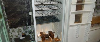
Although the light output is only 100-120 lumens, the dazzling white color makes the lamp appear much brighter. The assembled lamp can be used as a table lamp or to illuminate a compact room, for example, a corridor or closet.
Afterword
In conclusion, I would like to say a few words about the resulting review. Not every USB port on a computer can charge this flashlight, it all depends on its load capacity, 0.5 A should be enough. For comparison, cell phones may show charging when connected to some computers, but in reality there is no charging. In other words, if the computer charges the phone, then the flashlight will also charge.
The field-effect transistor circuit can be used to charge 1 or 2 battery cells from USB, you just need to adjust the voltage accordingly.
Conclusions and useful video on the topic
In the video below you can see a detailed description of a specialist about self-assembly of an LED lamp:
LED lamps, made independently, have high technical characteristics. They are almost as good as factory models in terms of qualities such as strength, reliability, and durability.
The assembly of such devices is accessible to almost everyone: to successfully complete it, you just need to strictly follow the diagrams and carefully carry out all the prescribed manipulations.
Perhaps you have already assembled an LED lamp with your own hands and can you give valuable advice to visitors to our site? Or did you have any questions after reading the article? Please leave your comments in the block below.
What is the difference between a power supply and a driver?
The LEDs are controlled by the power supply, and the driver takes part and is not a power supply. The power supply is connected to a 220V network, and the driver has a connection from 12 or 48V and regulates the light intensity.
If the power supply has the inscription “driver”, this means that it already has a stabilized voltage at its output. Power supplies can be isolated or non-isolated.
If the luminaire uses LEDs of different colors in the connection, you must use a controller. The information provided may not be clear to a beginner, but without understanding it, it will not be possible to make or repair an LED lamp.
Adding a capacitor
If you increase the supply voltage to the LEDs in order to make the light brighter, the LEDs will begin to heat up, which significantly reduces their durability. In order to avoid this, you need to connect a 10 W recessed or table lamp with an additional capacitor. Simply connect one side of the base to the negative output of the bridge rectifier and the positive side, through an additional capacitor, to the positive output of the rectifier. You can use 40 LEDs instead of the suggested 60, thereby increasing the overall brightness of the lamp.
Video: how to make an LED lamp with your own hands
If desired, a similar lamp can be made using a powerful LED, but then you will need capacitors of a different value.
As you can see, assembling or repairing a conventional DIY LED lamp is not particularly difficult. And it won't take much time and effort. This lamp is also suitable as a summer option, for example for a greenhouse; its light is absolutely harmless to plants.
The simplest LED light bulb to assemble
You will need:
- faulty energy-saving light bulb;
- HK6 LEDs;
- cardboard;
- tools: pliers, soldering iron.
Step-by-step instruction
Carefully separate the base part from the energy-saving diffuser housing. Usually it is assembled using special latches, which must be found and carefully hooked. If the plinth is attached using pinholes on it, you need to carefully drill them or cut them off with a hacksaw.
- Clean the base and degrease it with alcohol/acetone. Carefully remove excess solder from soldering areas.
- There are six holes on the base cover that were used to attach the gas outlet pipes. They will be the installation site for the ICE elements, to fix which you will need another piece of cardboard of the appropriate diameter with holes cut in it.
- HK6 LEDs consist of six crystals connected in parallel. Their power is small, but the stream of light is quite bright. Having inserted the light emitters into the base cell, connect them into two branches of three pieces in a parallel circuit. Next, both circuits must be connected in series to the output wires of the driver.
- Place the driver in the base. Install another circle of cardboard between it and the diode board (to prevent a short circuit between the diode contacts and the driver elements).
Distribute the incoming driver wires as follows: one is led out through the center of the base and soldered, the other will be fixed to the base thread during assembly. Secure the driver with hot glue.
- Connect the diode contacts to the second pair of driver wires. Solder all connections.
- Having installed the plate, glue it with hot glue and assemble the base.
- Solder the wire brought out to the thread.
- The bottom of a plastic bottle of a suitable size can be used as a diffuser.
This simplest manufacturing method costs practically nothing, with the exception of the purchase of six light emitters.
Resistor circuits
This scheme is quite capable even for novice masters. To assemble a device based on it, you need to buy 2 12k resistors, as well as a pair of circuits with the same number of chips soldered in series, taking into account polarity. One strip of diodes on the side (R2) is connected as the anode, and the other (R1) as the cathode. Devices that are assembled according to this scheme are distinguished by a soft light, since at the moment of switching on the LEDs light up one after the other.
Fig. 5 – resistor for an LED lamp.
Thanks to this effect, the naked eye practically does not see the pulsation. This bulb is best suited for a table lamp. To get optimal lighting, it is recommended to purchase strips with 20-40 diodes. If there are fewer of them, it will give an insignificant luminous flux. But the more elements, the more difficult the work is technically.
Idea N3 – Using LED strip
Another way to obtain an LED light bulb at home is to assemble a lamp from LED strips. By its design, the LED strip is a universal lighting device - it can be mounted on almost any surface. Therefore, the role of an LED chandelier with such bulbs can be played by any design.
However, diode strips also have a significant drawback - to power indoor models, a safe voltage of 12 V is used, which meets the requirements of clause 1.7.50 of the PUE . To implement such power supply, it is necessary to install a separate power supply. The dimensions of such a converter are quite impressive, so this idea is relevant to implement in those places where it can be hidden, for example, in a niche in a suspended ceiling.
- Determine the required length of the LED strip for the lamp based on the required lighting brightness. As a rule, for each model this parameter is indicated in the passport data.
- Select a power supply with sufficient power to connect the selected length of tape.
- Cut the LED strip into pieces according to the marks marked on it. It is most convenient to choose the length of the segments to a minimum (3 - 4 LEDs), they are easy to stick on any part.
Rice. 12. Cut the LED strip
- Cut the plastic pipe into pieces and glue the LED strip onto it.
Rice. 13. Cut the plastic pipe into pieces and apply tape
- Solder the resulting sections in parallel, several pieces for one lamp.
Rice. 14. Solder the required number of pieces of tape
- Connect the leads from the LED strip to the base; you can take them from an old incandescent or fluorescent light bulb, or connect directly to the power supply.
Rice.
15. Connect the lamp to the socket. Now you have an assembled lamp from an LED strip, which will fully replace a store-bought lamp. However, note that there are bare contacts on it, so when installing the lamp in a lamp or niche, the circuit must be de-energized.
Safety Tips
- Despite the fact that making an LED light bulb yourself is a fairly simple task, you should not even try to assemble it without having the necessary knowledge and skills in electrical work. Otherwise, homemade products can cause a short circuit that can damage the entire home network. It is typical for LED technology that if the connection diagram is incorrect, an explosion is also possible.
- The home network uses alternating current with a voltage of 220 volts. You should always remember this and not connect lamps and other devices designed for 12 volts to your home network.
- It is recommended to connect the contacts using soldering. If you use an adhesive instead, the reliability of the connection will be low and the product will quickly fail.
The assembly methods presented above do not require significant financial outlays, except for the purchase of LEDs and a small amount of consumables. The main elements used are used parts from burnt-out appliances. The cost of homemade products is several times lower than those purchased in a store. Having acquired installation skills, you can make lamps of varying brightness as you wish.
Model based on an energy-saving light bulb
You will need:
- faulty energy-saving light bulb;
- a piece of fiberglass;
- resistors;
- capacitor;
- LEDs;
- auxiliary materials: table salt, nail polish, copper sulfate;
- tools: soldering iron, drill.
Step-by-step instruction
- Cut the fiberglass board in the shape of a circle d=3 cm.
- Using nail polish, apply the circuit diagram to the board.
- Dissolve 1 tbsp in warm water. l. copper sulfate and 2 tbsp. l. salt.
- After the varnish has hardened, place the board in the resulting solution for one day. As a result of the reaction, the copper coating of the board will disappear, with the exception of the drawing protected by varnish.
- Remove the varnish from the board with acetone and tin the tracks.
- Drill holes using a drill according to the drawing.
- Solder all driver elements.
- Disassemble the old energy saving box, leaving only the wiring coming from the base.
- Install the board in the base part, solder the wires, and secure the board with glue.