Second life for old drives
Many are interested in the secondary use of components of equipment with a status of obsolete. There are already interesting publications on Internet resources about where to find uses for old CD or DVD drives.
One of the craftsmen made his own CNC machine from a DVD-Rom, although a CD-ROM is also suitable for control. Everything that is available is used. The machine is intended for the manufacture of printed circuit boards in electronics and milling and engraving of small workpieces. The sequence of work can be formulated as follows:
- You will need three DVD drives for precise positioning in order to move the coordinate machine along three axes. The drives must be disassembled and unnecessary elements removed. Only the stepper motor along with the sliding mechanism should remain on the chassis.
IMPORTANT! The chassis of the disassembled drive must be metal, not plastic
Since the DVD motor is bipolar, it is enough to ring both windings with a tester to determine their purpose. Some people doubt whether the motor has enough power or whether the working unit has moved the required distance? To reduce engine forces, it is important to decide that the table will be movable and not a portal type. The base of the bed is 13.5x17 cm, and the height of the bars for the vertical stand of the machine is 24 cm. Although DVD drives from manufacturers may differ in size. Next, you need to take the stepper motors to solder the control wires (it doesn’t matter - these will be motor contacts or a cable cable). Since connection with screws is not acceptable here, wooden rectangles (future platforms) that will move along three axes must be glued to the moving parts of the engine. The spindle will be an electric motor with two screw clamps
It must be extremely light, otherwise it will be difficult for CD/DVD mechanisms to lift it.
The procedure for calculating the resolution of a stepper motor dvd drive
To measure the resolution of a CD/DVD drive stepper motor, you need a digital micrometer. The distance along the screw has already been measured. The total length of the screw was measured using a micrometer, which turned out to be 51.56 mm. Next, you need to determine the lead value, which is the distance between two adjacent threads on the screw. Threads were designed for 12 threads within this distance. Retraction = distance between adjacent threads = (total length / number of threads = 51.56 mm) / 12 = 4.29 mm / rev. The pitch angle is 18 degrees, which corresponds to 20 steps/revolution. Now that all the necessary information is available, the resolution of the stepper motor can be calculated as shown above: Resolution = (Distance between adjacent threads) / (N steps / revolution) = (4.29 mm / revolution) / (20 steps / revolution) = 0.214mm/step. Which is 3 times better than the required resolution, which is 0.68 mm/step.
Electronic component
The laser diode selected is a 1.5 W, 445 nm diode housed in a 12 mm package with a focusable glass lens. These can be found, pre-assembled, on eBay. Since it is a 445 nm laser, the light it produces is visible blue light.
The laser diode requires a heatsink when operating at high power levels. When constructing the engraver, two aluminum supports for SK12 12 mm are used, both for mounting and for cooling the laser module.
The output intensity of a laser depends on the current that passes through it. A diode by itself cannot regulate current, and if connected directly to a power source, it will increase current until it fails. Thus, an adjustable current circuit is required to protect the laser diode and control its brightness.
Another option for connecting the microcontroller and electronic parts:
What can you do with a laser engraver using disk drives?
A laser engraver, assembled on the basis of old disk drives, allows you to apply a variety of inscriptions and drawings to almost all materials of organic origin, that is, those that can char or melt. These include:
- wood;
- skin;
- thick paper and cardboard;
- most types of plastic;
- rubber, etc.
A laser engraver made from disk drives can be used to engrave small parts - souvenirs, household items, signs, etc.
Lasersolid 530 Lite laser engraving machine
- Power supply 110V or 220-240V/ 50~60Hz
- Dimensions, mm 1150x670x300
- Laser tube power 50 W
- Working field 300 x 500
- Resolution, DPI 1000
- Engraving speed 200 mm/s
- Beam travel speed 500 mm/s
- CO2 laser type
- Engraving accuracy 0.01
- USB 2.0 interfaces
- Cooling Water
- Motor type stepper
You can also make a laser engraver
To build a laser module, a software goal is set: it must have easy focusing, a fairly rigid structure, and it must be manufactured using only available materials.
It’s worth checking out the brief instructions offered by another DIYer.
You will need to stock up on the following components:
- electric motor from the DVD drive;
- laser diode and plastic lens from the DVD drive (up to 300 MW so that it does not melt);
- metal washer with an internal diameter of 5 mm;
- three screws and the same number of small springs from a ballpoint pen.
This engraver has two movement mechanisms; vertical movement for the laser is not needed. A laser LED is used as a cutting or burning tool.
ATTENTION! You need to know the intricacies of the laser. Even its occasional reflection can damage your eyesight.
Extreme caution is required.
Since the diameters of the laser diode and the hole in the motor housing are slightly different, the smaller one will have to be widened. The conductors soldered to the diode should be insulated using heat shrink tubing.
The diode is pressed into the hole so that good thermal contact is achieved between them. The laser diode on top can be covered with a brass sleeve taken from this engine. Three cutouts are made in the washer for the screws. The lens, inserted into the hole in the washer, is carefully glued, avoiding any glue getting on it.
The lens is attached to the body. After making sure that it can move freely along the bolts, the position is fixed. Using screws, focus the beam as accurately as possible. This laser from DVD drives is used in engraving technology.
Required parts and materials:
- Arduino Nano (with USB cable)
- 2x DVD drive stepper mechanism
- 2 x A4988 Stepper Motor Driver Modules (or GRBL Shield)
- 250 mW laser with adjustable lens (or higher)
- 12V 2Amp minimum power supply
- 1x IRFZ44N N-CHANNEL Mosfet
- 1x 10k resistor
- Resistor 1x 47 Ohm
- 1x Voltage Regulator LM7805 (with heatsink)
- Blank PCB
- Male and Female heads
- 2.5mm JST XH-Style
- 2-pin connector
- 1x 1000uF 16V capacitor jumper cables
- 8x small neodymium magnets (which I salvaged from the DVD lens mechanism)
- 1x 2-pin plug in terminal block screw connector
- Transport tape (100 mm)
- Super glue
- 6x M3x12 screws
- 8x M2x5 screws
- Laser safety glasses.
You will need two DVD drive mechanisms, one for the X axis and one for the Y axis. Using a small Phillips head screwdriver, remove all the screws and the disconnected stepper motor, slide rails, and pusher. Stepper motors are a 4-pin, two-pole stepper motor.
The small size and low cost of the DVD motor means that you should not expect a high resolution motor. This is ensured by the lead screw. Also, not all such motors do 20 steps/24 rev, which is also a common specification. You just need to test your engine to see what it can do.
Installing and configuring grbl.
I have already described how to load the grbl firmware into the Arduino UNO more than once, for example in the article: “Installing and configuring the LaserGRBL program.”, but here we will use a slightly modified firmware, just for this project. Therefore, I will repeat all the steps that need to be taken.
Installing Arduino IDE.
First, you need to install the Arduino IDE programming environment. If you have it installed, then you can safely skip this point.
I have already told you how to install and configure the Arduino IDE program in the article: “Arduino IDE program, free for Windows, Mac OS, linux. Flashing Arduino." Therefore, I will briefly tell you the main stages of installation and configuration for the Windows operating system.
Installing the ch340 driver.
- Download the driver at the bottom of the article in the “downloads” section;
- Unpack the archive;
- Run the executive file “CH341SER.EXE”;
- In the window that opens, click the Install button;
- This completes the installation.
Please note: DIY mechanical saw for metal
Now you can proceed directly to loading the GRBL library.
Installing the grbl library.
As I wrote earlier, we will not use the standard GRBL library. You can find the required library by request in the “Grbl Pen Servo” search engine, or download it at the bottom of the page in the “files for download” section.
Attention!!! You must definitely remove the GRBL library if you installed it before. To do this, go to the “Documents\Arduino\libraries” folder and look for the “grbl” folder and delete it
Next you need to install the grbl library. This can be done in two ways:
- Copy the grbl folder from the archive to the folder with the Arduino libraries, which is located in the following path: Documents\Arduino\libraries.
- Install via library manager:
Go to the Arduino IDE and select from the menu: Sketch -> Connect library -> Add .ZIP library...
Select the downloaded grbl.zip archive and click the “Open” button. After installation, you will see a message that the library was added successfully.
Loading grbl into Arduino UNO.
After installing the grbl library, go to the Files -> Examples menu, and look for the “grbl” example in the list. Open the example “grblUpload”.
There is no need to change anything in the example; it needs to be loaded into the Arduino UNO. To do this, in the “Tools” menu item, select the “Arduino UNO” board and the port to which the board is connected. In my case it is "COM9".
Now we can load the GRBL firmware into the Arduino UNO. To do this, click on the “Download” button. After compiling the sketch, the code will be loaded into the microcontroller. And you will see the message “Download Complete”.
You will also see an orange message “Insufficient memory, the program may be unstable.” But don't worry, everything will work perfectly.
DIY laser engraver: materials, assembly, software installation
Many of those home craftsmen who manufacture and decorate products from wood and other materials in their workshop have probably wondered how to make a laser engraver with their own hands.
The presence of such equipment, the serial models of which are quite expensive, makes it possible not only to apply complex patterns to the surface of the workpiece with high precision and detail, but also to perform laser cutting of various materials.
Homemade laser machine in the process of wood engraving
A homemade laser engraver that will cost much less than a production model can be made even if you do not have a deep understanding of electronics and mechanics.
The laser engraver of the proposed project is assembled on the Arduino hardware platform and has a power of 3 W, while for industrial models this parameter is at least 400 W.
However, even such a small power allows this machine to be used for cutting products made of polystyrene foam, cork sheets, plastic and cardboard, as well as for high-quality laser engraving.
This engraver can handle even thin plastic
Necessary materials
To make your own laser engraver using Arduino, you will need the following consumables, mechanisms and tools:
- hardware platform Arduino R3;
- The prototype board is equipped with a display;
- stepper motors, which can be electric motors for printers or DVD players;
- 3 W laser;
- laser cooling device;
- DC/DC constant voltage regulator;
- MOSFETs;
- electronic boards that control the laser engraver motors;
- stop switch;
- a case in which you can place all the structural elements of a homemade engraver;
- timing belts and pulleys for their installation;
- ball bearings of various sizes;
- four wooden boards (two 135x10x2 cm and the other two 125x10x2 cm);
- four round metal rods with a diameter of 10 mm;
- bolts, nuts and screws;
- lubricant;
- cable ties;
- computer;
- drills of various diameters;
- a circular saw;
- sandpaper;
- vice;
- standard set of locksmith tools.
The electronic part of the machine will require the largest investment
Electrical part of a homemade laser engraver
The main element of the electrical circuit of the presented device is a laser emitter, the input of which must be supplied with a constant voltage, the value of which does not exceed the permissible parameters.
If this requirement is not observed, the laser may simply burn out.
The laser emitter used in the engraving installation of the presented design is designed for a voltage of 5 V and a current of no more than 2.4 A, so the DC-DC regulator must be set to a current of 2 A and a voltage of up to 5 V.
Electrical circuit of the engraver
The MOSFET transistor, which is the most important element in the electrical part of a laser engraver, is required to turn the laser emitter on and off when receiving a signal from the Arduino controller.
The electrical signal generated by the controller is very weak, so only the MOSFET can detect it and then turn the laser power circuit on and off.
In the electrical circuit of a laser engraver, such a transistor is installed between the positive contact of the laser and the negative DC regulator.
The laser engraver's stepper motors are connected via an electronic control board, which ensures their synchronization. Thanks to this connection, timing belts driven by multiple motors do not fall down and maintain a stable tension during operation, which guarantees the quality and accuracy of the work performed.
To do this, it is necessary to ensure its effective cooling. This problem can be solved quite simply - a regular computer fan is installed next to the diode. To prevent overheating of stepper motor control boards, computer coolers are also placed next to them, since conventional radiators cannot cope with this task.
Build process
The homemade engraving machine of the proposed design is a shuttle-type device, one of the moving elements of which is responsible for movement along the Y axis, and the other two, connected to each other, for movement along the X axis.
The Z axis, which is also indicated in the parameters of such a 3D printer, is the depth at which the material being processed is fired.
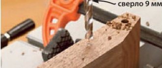
The depth of the holes into which the elements of the shuttle mechanism of the laser engraver are installed must be at least 12 mm.
Aluminum rods with a diameter of at least 10 mm can serve as guide elements along which the working head of the laser engraving device will move.
If aluminum rods cannot be found, steel guides of the same diameter can be used for these purposes.
The need to use rods of this diameter is explained by the fact that in this case the working head of the laser engraving device will not go down.
The surface of the rods that will be used as guide elements for the laser engraving device must be cleaned of factory grease and carefully sanded to obtain ideal smoothness. They should then be coated with a white lithium-based lubricant, which will improve the sliding process.
Housing assembly
Installation of stepper motors on the body of a homemade engraving device is done using sheet metal brackets.
To make such a bracket, a sheet of metal approximately the width of the motor itself and twice as long as its base is bent at a right angle.
On the surface of this bracket, where the base of the electric motor will be located, 6 holes are drilled, 4 of which are necessary for fixing the motor itself, and the other two are necessary for attaching the bracket to the body using standard self-supporting screws.
A suitably sized piece of sheet metal is also used to mount the drive mechanism, which consists of two pulleys, a washer and a bolt, on the motor shaft.
To install such a device, a U-shaped profile is formed from sheet metal, in which holes are drilled for its attachment to the engraver body and exit from the motor shaft. The pulleys on which the timing belts will be attached are installed on the traction motor shaft and placed in the inner part of the U-shaped profile.
Toothed belts, which are mounted on the pulleys that are supposed to drive the shuttles of the engraving device, are connected to their wooden bases using self-tapping screws.
Software installation
Your laser cultivator, which must operate in automatic mode, will require not only installation, but also configuration of special software.
The most important element of this support is a program that allows you to create the contours of the desired model and convert them into an understandable extension for the laser engraver controls.
This program is available for free and you can download it to your computer without any problem.
The program downloaded to the computer that controls the engraving device is unpacked from the archive and installed. In addition, you will need a library of circuits and a program that will send data about the design or lettering created to the Arduino controller."
In order for your homemade laser product to work properly and the engraving performed with its help to be of high quality, you will need to configure the controller itself to the parameters of the engraving device.
Features of using contours
If you have already figured out the question of how to make a hand-held laser engraver, then you need to clarify the question about the parameters of the contours that can be applied using such a device.
Such contours, the inside of which is not painted over even when the original drawing is repainted, should be transferred to the engraver controller via files not in pixel (jpeg), but in vector format.
This means that the image or inscription applied to the surface of the workpiece using such an engraver will not consist of pixels, but of dots. The size of such images and inscriptions can be changed at will, focusing on the surface on which they will be applied.
Using a laser engraver, almost all drawings and inscriptions can be applied to the surface of a product, but to do this, their computer models must be converted into vector format.
This procedure is simple - special programs Inkscape or Adobe Illustrator are used for this. A file that has already been converted to a vector format must be converted again in order for it to be correctly accepted by the engraving machine controller.
Inkscape Laserengraver is used for this conversion.
Final setup and preparation for work
Having made a laser engraving machine with your own hands and loaded the necessary software into its control computer, do not immediately start working - the equipment needs final configuration and configuration.
What kind of adjustment is this? First of all, you need to make sure that the maximum movements of the machine's laser head along the X and Y axes coincide with the values obtained when converting the vector file.
Also, depending on the thickness of the material from which the part is made, it is necessary to adjust the parameters of the current supplied to the laser head. This should be done so that the product does not burn on the surface you want to engrave.
A very important and responsible process is the precise alignment (adjustment) of the laser head. Alignment is necessary to adjust the power and resolution of the beam produced by your engraver's laser head.
On expensive serial models of laser engraving machines, adjustment is performed using an additional low-power laser installed in the main working head.
However, homemade engravers usually use inexpensive laser heads, so this method of beam adjustment is not suitable for them.
Test your DIY laser engraver first with simple designs
Sufficiently high-quality adjustment of a homemade laser engraver can be done using the LED removed from the laser pointer. The LED wires are connected to a 3V power source and attached to the working end of a standard laser.
By alternately turning on and adjusting the position of the beams emanating from the test LED and the laser head, they achieve alignment at one point.
The convenience of using an LED from a laser pointer is that adjustment can be made with its help without the risk of damaging both the hands and eyes of the engraving machine operator.
Basics of assembling an engraver on Arduino
To begin with, I suggest you look at what the entire process of creating an engraver looked like for one radio amateur:
Strong stepper motors also require drivers to get the most out of them. In this project, a special stepper driver is used for each motor.
Below is some information about the selected components:
- Stepper motor – 2 pieces.
- Frame size is NEMA 23.
- Torque is 1.8 lb-ft at 255 oz.
- 200 steps/revolutions – 1 step 1.8 degrees.
- Current – up to 3.0 A.
- Weight – 1.05 kg.
- Bipolar 4-wire connection.
- Stepper driver – 2 pieces.
- Digital stepping drive.
- Chip.
- Output current – from 0.5 A to 5.6 A.
- Output current limiter – reduces the risk of motor overheating.
- Control signals: Step and Direction inputs.
- Pulse input frequency – up to 200 kHz.
- Supply voltage – 20 V – 50 V DC.
For each axis, the motor directly drives the ball screw through the motor connector. The motors are mounted on the frame using two aluminum corners and an aluminum plate. The aluminum corners and plate are 3mm thick and are strong enough to support a 1kg motor without bending.
Important! The motor shaft and ball screw must be properly aligned. The connectors that are used have some flexibility to compensate for minor errors, but if the alignment error is too large, they will not work!. Another process of creating this device can be seen in the video:
Another process of creating this device can be seen in the video:
Parts used for the driver:
- Arduino nano.
- 2x A4988 Stepper motor drivers.
- 1x IRFZ44N N-CHANNEL MOSFET.
- 1x LM7805 Voltage regulator with heatsink.
- 1x 47 ohm and 1x 10 kohm resistor.
- 1x 1000uF 16V capacitor.
- 1x 2.5mm JST XH-Style 2-pin connector.
- Male and female header pins.
- 1x (20mm x 80mm blank PCB).
GRBL protects the digital and analog pins of the Arduino.
The stepper pin for the X and Y axes is attached to digital pins 2 and 3 respectively. The "Dir" pin for the X and Y axes is attached to digital pins 5 and 6 respectively. D11 for laser activation. The Arduino receives power via a USB cable. A4988 drivers via external power supply. The entire foundation has common connections. VDD A4988 are connected to 5V Arduino. The laser that was used operates at 5V and has a built-in DC circuit. To supply 5V DC voltage from an external power supply, an LM7805 voltage regulator is used. A radiator is a must. IRFZ44N N-CHANNEL MOSFET works as an electronic switch when it receives digital high signal from Arduino pin D11. NOTE : We use 5V from Arduino Nano
What about interaction?
It’s surprising to listen to the statements of some craftsmen that Arduino is not suitable for CNC, especially since mach3 arduino symbiosis is impossible, supposedly they do not want to interact.
Others are sure otherwise: Arduino can be implemented for CNC using three options:
- Completely autonomous controller.
- The interpreter board is responsible for the movements, but they are calculated on the computer.
- Translator board (adapter) - acts as a virtual LPT port.
Many users on the network who have problematic electronics ask for advice on a program so that machines controlled by one can work smoothly and smoothly. The milling machines on the machine are designed to process the workpiece evenly, following the signals of the program block.
Homemade tool for cutting and processing plywood
Considering the high cost of factory equipment, more and more people are trying to make a plywood laser cutting machine with their own hands. However, before embarking on such a procedure, make sure that you have certain skills and are willing to invest a lot of time and effort into the task ahead.
When manufacturing laser equipment, a number of features should be taken into account:
Determine the power indicators of the future car. It is no secret that at the stage of creating a system it is necessary to use special expensive devices with high power ratings, so the total cost of the final model is at least $600.- Find the right batteries and cooling. As mentioned above, to cool the gas moving through the pipe, it is necessary to use water and a pump that will pump it to the most vulnerable components of the system. For normal operation, the machine requires at least 100 liters of fluid.
- Therefore, it is necessary to fine-tune all elements of the laser system. To perform such an action, you must have at least minimal experience and spend a lot of time. This suggests that sometimes it is much easier to purchase a ready-made invention than to try to create it yourself, but everything is ambiguous.
Laser cutting of plywood sheets remains a complex process, but with the right approach it can create real works of art and intricate patterns.
G-Code creation program and control program.
I had a problem choosing a program to create G-code. But I’ll tell you about this next time, and now I’ll write a list of programs that I used. In the next article I will tell you why the choice fell on these programs.
Inkscape.
A program for working with vector graphics. The program has a plugin for creating G-code, but it is not suitable for our work. Makes a double stroke. I already talked about this program in the article: “Inkscape where to download the Russian version. Setting up Inkscape"
Carbide Create V5.
Carbide Create is a free CAD/CAM program developed by manufacturers of small CNC machines “Carbide 3D”. In this program you can create small drawings, as well as generate G-Code from vector drawings in .svg format. The program is not bad, but there are a number of disadvantages. About them in the next article.
Candle.
Candle is a control program for CNC machines. It is entirely in Russian. Quite functional and not complicated. But there is no easy way to configure GRBL configuration.
Please note: Review of 10 new internal combustion engines
Universal G-codeSender.
Excellent control program. In the settings you can select Russian language. But, unfortunately, problems constantly arise on a computer with the Windows operating system. I used it on Linux and it works great. I use this program to demonstrate the ease of setting up the GRBL configuration.
Continued in the next article.
Did you like the DIY CNC plotter project on Arduino? Don't forget to share with your friends on social media. networks.
And also subscribe to our channel on YouTube, join the group, join the group on.
Thank you for your attention!
Technology starts simple!
Photos for the article
Downloads
By downloading the material, I agree to the Rules for Downloading and Using Materials.
| Grbl Pen Servo.zip | 143 Kb | 199 | Download |
| Universal G-code Sender.zip | 28368 Kb | 209 | Download |
| Carbide Create.zip | 48999 Kb | 245 | Download |
| Candle 1.1.7.zip | 29095 Kb | 225 | Download |
| driver CH340G.zip | 186 Kb | 190 | Download |
Laser for metal engraving and how the device works
There is no point in describing in words how to make a laser engraver with your own hands from an Arduino Uno or a 3D printer. It will be much more instructive to see everything with your own eyes. We invite you to see how to make a similar CNC laser engraver.
Watch this video on YouTube
After all, even a photograph can be engraved on a laser machine of this type by launching the desired program. Many people ask how to prepare a photo for engraving on a laser machine. It's simple: the photo is scanned and uploaded into the program.
Photogravure on metal
Why are shields needed?
Owners of homemade devices have heard a lot about expansion boards - Arduino cnc shield, the use of which expands the functionality of milling equipment.
Usually the shield is made to fit the form factor of the board. They also use several shields at the same time, installing them on the microcontroller (one on top of the other). Range of their application:
- using the official Arduino device - Ethernet cnc shield, you can achieve independence of the project from the PC, and it is also used for hosting a web server;
- 4 Relay Shield – the ability to connect 4 peripheral devices;
IMPORTANT: You must be careful with the pins of this device so as not to damage the Arduino. https://www.youtube.com/embed/1ZX3qf8x9iA
- Protoshield is a very useful shield at the moment when the circuit is being assembled;
- LCD Shield allows information from Arduino to be output directly to a peripheral screen;
- Energy Shield - advanced power options for Arduino. Recharging mobile phones and gadgets is possible;
- motor shield provides control and protection for a large number of motors;
- SD Card Shield is used for processing and storing large amounts of information;
- Wi-fi Shield connected to the serial port will provide remote control of the drives of robotic projects;
- GPRS Shield is equipped with antennas for using the GSM/GPRS network;
- E-Ink shield is a way to use electronic ink technology; the display needs a minimum of energy to power it;
- Music Shield is capable of playing music through Arduino in excellent quality.
It is possible to create a 3D laser printer or CNC machine using budget Arduino boards. With the CNC Shield expansion board, you can work on CNC machines, engraving or milling machines. And the shield for controlling three SDs (three-axis machine) has three connectors, so that there are no problems with each driver when connecting.
Electrical part of a homemade laser engraver
The main element of the electrical circuit of the presented device is a laser emitter, the input of which must be supplied with a constant voltage, the value of which does not exceed the permissible parameters. If this requirement is not observed, the laser may simply burn out. The laser emitter used in the engraving installation of the presented design is designed for a voltage of 5 V and a current of no more than 2.4 A, so the DC-DC regulator must be set to a current of 2 A and a voltage of up to 5 V.
Electrical circuit of the engraver
The MOSFET transistor, which is the most important element in the electrical part of a laser engraver, is required to turn the laser emitter on and off when receiving a signal from the Arduino controller. The electrical signal generated by the controller is very weak, so only the MOSFET can detect it and then turn the laser power circuit on and off. In the electrical circuit of a laser engraver, such a transistor is installed between the positive contact of the laser and the negative DC regulator.
The laser engraver's stepper motors are connected via an electronic control board, which ensures their synchronization. Thanks to this connection, timing belts driven by multiple motors do not fall down and maintain a stable tension during operation, which guarantees the quality and accuracy of the work performed.
It should be taken into account that the laser diode used in a homemade engraving machine should not overheat.
To do this, it is necessary to ensure its effective cooling. This problem can be solved quite simply - a regular computer fan is installed next to the diode. To prevent overheating of stepper motor control boards, computer coolers are also placed next to them, since conventional radiators cannot cope with this task.
Photo of the assembly process, connection diagram
Photo-1 Photo-2 Photo-3 Photo-4 Photo-5 Photo-6
Assembling a homemade plotter on Arduino.
For the project you will need the following electronics:
- ARDUINO UNO.
- CNC shield v3, read the description in the article: “CNC board for Arduino UNO, CNC shield v3 and driver A4988 (DRV8825).”
- 2 x NEMA 17 17HS4401 stepper motors. With wires that come included.
- 2 A4988 drivers. You can read about them in the article: “A4988 Stepper Motor Driver”.
- 12 volt power supply.
- Servo 9g.
Assembly of machine mechanics.
I recently made a unit out of pencils (a CNC carriage), and based on this carriage I decided to build a CNC plotter. But you need at least 2 axles, so I assembled a second unit, but a little narrower. This is what the X and Y axis nodes look like for a homemade machine.
You can read how to assemble the carriage in the previous article. I can say one thing about it: it is made of pencils, construction pins and plywood.
I changed the base of the wide carriage to a wider one. This will help eliminate unnecessary vibration of the machine, and there will be a surface on which you can attach a piece of paper.
I install the second carriage on the moving part of the first carriage, at an angle of 90 degrees. And I secure it with self-tapping screws.
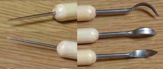
It will not be possible to use a regular handle in this project, since you need a movable mechanism, as well as fasteners for it. To do this, I bought at a stationery store: a gel pen, a fountain pen and a goat’s leg compass.
I took out the paste from the gel pen and installed a spring from a fountain pen on the edge. I also cut off the edge at the bottom of the pasta. So that it falls into the body of the handle.
I installed the paste in the handle and checked it by pressing it with my finger. The paste falls through and then returns under the action of a spring.
I wound and glued the thread onto the paste. Here I made a mistake, I used cotton thread. It got used to me literally after 2 hours of work. I replaced it with a nylon thread and applied lubricant to it.
I made holes in the body of the pen and threaded it through. I installed the paste in place.
I installed a servo drive on the X-axis, attaching it with self-tapping screws.
Using a goat leg compass holder, I attached the handle to the X axis.
I tied the thread from the handle to the servo rocker. I secured the rocker with a screw.
All the mechanics have been assembled, now you can install the remaining components and check the functionality of the machine.
Installation of plotter electronics.
We have most of the electronics installed. Namely, the stepper motors are in place, the servo drive is installed. All that remains is to install the control electronics.
Please note: DIY electromagnetic pulse diagram. electromagnetic weapons. creation of a portable em radiation device
On the prepared plywood, I installed the Arduino UNO board.
On top of the Y-axis motor I installed a plywood with Arduino.
I installed CNC shield v3 and 2 A4988 drivers on Arduino UNO.
All that remains is to connect everything, and for this you need a connection diagram.
Connection diagram for CNC plotter electronics on Arduino UNO and CNC shield v3.
The connection diagram is very simple and does not require additional wires.
I connect the stepper motors with the wires that come with the kit.
To connect the servo drive, you need to remove the information wire from the block, it is usually orange, and connect it to the Z+ pin, and connect the servo drive power wires to the 5v and GND pins on the CNC shield.
The connection is the simplest of all my homemade CNC machines. That's why many people start assembling their first CNC machines with a plotter.
Final setup and preparation for work
Having made a laser engraving machine with your own hands and loaded the necessary software into its control computer, do not immediately start working - the equipment needs final configuration and configuration. What kind of adjustment is this? First of all, you need to make sure that the maximum movements of the machine's laser head along the X and Y axes coincide with the values obtained when converting the vector file. Also, depending on the thickness of the material from which the part is made, it is necessary to adjust the parameters of the current supplied to the laser head. This should be done so that the product does not burn on the surface you want to engrave.
A very important and responsible process is the precise alignment (adjustment) of the laser head. Alignment is necessary to adjust the power and resolution of the beam produced by your engraver's laser head. On expensive serial models of laser engraving machines, adjustment is performed using an additional low-power laser installed in the main working head. However, homemade engravers usually use inexpensive laser heads, so this method of beam adjustment is not suitable for them.
Test your DIY laser engraver first with simple designs
Sufficiently high-quality adjustment of a homemade laser engraver can be done using the LED removed from the laser pointer. The LED wires are connected to a 3V power source and attached to the working end of a standard laser. By alternately turning on and adjusting the position of the beams emanating from the test LED and the laser head, they achieve alignment at one point. The convenience of using an LED from a laser pointer is that adjustment can be made with its help without the risk of damaging both the hands and eyes of the engraving machine operator.
The video shows the process of connecting the engraver to a computer, setting up the software and preparing the machine for work.
For those who like to burn on various materials
On the Internet you can see numerous homemade models of burners that are capable of creating designs on plywood, plastic, metal and even glass. Moreover, photographic similarity and some three-dimensionality of the image are achieved. The surface is cleaned, degreased, primed with white acrylic of the Kudo brand and, using a CNC laser burner, also called a pyroprinter, unique images are created. Sometimes the process lasts 6 or more hours.
The burner's operating speed is a stable 10 m/min, and programmers have ideas on how to raise it without interfering with the operation of the control unit. You can also control the burner from a laptop (Windows XP and 7) without using the LPT cable. This will turn burning into an exciting activity for children and teenagers using the capabilities of laser cutters.
Laser wood engraver: necessary materials and step-by-step instructions
Making a homemade laser engraver for wood processing is quite simple. Enough hands and a little imagination. By the way, with the help of such a device it will be possible to apply inscriptions not only on a wooden surface, but also on a plastic or leather surface, for example, on a belt.
And, to keep things simple, it will not be powered by a battery, but by a regular computer via a USB cable. However, if you need to make your DIY wood engraving device portable, you can use a regular power bank.
Power bank can be used as a battery
To make it you will need:
- 2 cartridges of depleted caliber 8 mm and 7.62 mm shortened (starter or gas pistol and TT);
- laser LED (about 250-300 mW), which can be removed from an old DVD drive;
- target from the same unit;
- USB connector;
- brass tube with an internal diameter of 10 mm;
- 3 resistors with a total resistance of 30 Ohms;
- 50 Ohm resistor;
- thin threads;
- power button.
Of course, you can’t do it without a soldering iron, a drill, a power drill, and your favorite hot glue. When everything you need is ready, you can start working. And how to do this will be described in step-by-step instructions with photo examples and detailed explanations.
The most used tool for everything
How can you use Arduino
A small board that has its own processor and memory, contacts - Arduino - is used in the process of designing electronic devices. This is a kind of electronic constructor that interacts with the environment. Through contacts to the board you can connect light bulbs, sensors, motors, routers, magnetic locks to doors - anything that is powered by electricity.
Arduino is effective for developing programmable devices that can do many things:
- plot the route of movement of the device (CNC machine);
- in partnership with Easydrivers, you can control the stepper motors of the machine;
- PC software can be implemented through this open programmable platform;
- connecting a Line Track Sensor to Arduino will allow you to track white lines on a dark background and vice versa;
- it is used to build a robot and various machine components;
- perform restriction of stepper motors (when traveling abroad).
Necessary materials
To make your own laser engraver using Arduino, you will need the following consumables, mechanisms and tools:
- hardware platform Arduino R3;
- The prototype board is equipped with a display;
- stepper motors, which can be electric motors for printers or DVD players;
- 3 W laser;
- laser cooling device;
- DC/DC constant voltage regulator;
- MOSFETs;
- electronic boards that control the laser engraver motors;
- stop switch;
- a case in which you can place all the structural elements of a homemade engraver;
- timing belts and pulleys for their installation;
- ball bearings of various sizes;
- four wooden boards (two 135x10x2 cm and the other two 125x10x2 cm);
- four round metal rods with a diameter of 10 mm;
- bolts, nuts and screws;
- lubricant;
- cable ties;
- computer;
- drills of various diameters;
- a circular saw;
- sandpaper;
- vice;
- standard set of locksmith tools.
The electronic part of the machine will require the largest investment
CNC machine made of wood
It requires Arduino uno R3, G-code Sender and GRBL. It is necessary to prepare materials and components in advance: plywood, nuts and bolts, threaded shaft and steel rods, ball bearings, Nema 23 motor and drivers for them, power supply 24 V, 15 A, bushings made of caprolon, fluoroplastic and metal, wires.
Much of the electronics were sent from China.
The base is made of wood blocks with blind, through holes. A steel threaded shaft installed in the center of the machine serves as a drive for the X-axis. At the moment of its rotation, the carriage (work table) moves along this X-axis.
ATTENTION: the thicker the plywood or wooden block, the less vibration there will be and the higher the positioning accuracy. https://www.youtube.com/embed/r3K3FaF_o8M
The portal (Y axis) is installed on a movable table, secured with a nut under the table. The Z axis serves to move the working element (it feeds the tool in a vertical position).
You will need bolts and nuts for assembly. You shouldn’t glue broken ones together; it’s better to replace them with new ones. When connecting Arduino, SD and drivers to each of them, it is necessary to provide power supplies for them. Once you have downloaded and configured the GRBL code, you can open G-code Sender and connect your Arduino to your PC. The board is ready to participate in the process of controlling the CNC machine.
To set the processing path, drawings of any CAD program are used. A CAM program is then used to generate the G-code.
CNC device manufacturing
For large volumes of work, a conventional engraver will not cope with the load. If you will be using it frequently and a lot, you will need a CNC device.
Assembling the interior
You can even make a laser engraver at home. To do this, remove the stepper motors and guides from the printer. They will fire a laser.
The complete list of required spare parts is as follows:
- Laser diode from a recording device.
- Radiator for diode.
- 3 stepper motors.
- 6 round guides.
- Fasteners for guides.
- 3 double trolleys or 6 single trolleys.
- Power supply 5 V, 4 A.
- Arduino UNO.
- 2 stepper motor drivers.
- 2 switches.
- Sheet 50 x 50 cm and 2 mm thick (for the base).
- Large sheet of plywood.
- Corners for fastening plywood.
- Self-tapping screws.
- 2 furniture hinges.
- Wires with a cross section of 0.5 mm².
- Mobile cable channel.
- Plastic ties.
- Transistor IRFZ44.
- 2 pressure rollers.
- 5 gears.
- Metal rod (axle for gears and rollers).
- 4 bearings.
- Toothed belt.
- 2A DC-DC Buck Converter
- Four limit switches.
- Clock button.
- 2.1 x 5.5 mm connector.
- 4 rubber or silicone feet.
- Heat transfer adhesive.
- Epoxy resin with hardener.
Measure the length of the guides and divide them into two groups. The first one will have 4 short ones, the second one will have 2 long ones. Rails of one group must be the same length.
Add 10 centimeters to the length of each group of guides and cut the base according to the resulting dimensions. From the cutouts, fold U-shaped supports for fasteners and weld them to the base. Mark and drill holes for the bolts inside them.
Drill a hole in the heatsink and glue the laser there using heat-conducting glue. We solder the wires and transistor to it. Screw the radiator to the cart.
Install the rail supports onto the two supports and secure them with bolts. Insert the Y-axis guides into the fasteners, install the X-axis carriages on their free ends. Insert the remaining guides with the laser head installed on them. Place the mounts onto the Y-rails and screw them to the holders.
Drill holes at the mounting points of the electric motors and gearbox axles. Reinstall the stepper motors and slide the drive gears onto their shafts. Insert the pre-cut strips from the metal rod into the holes and secure them with epoxy glue. After hardening, put the gears and pressure rollers with bearings inserted into them onto the axles.
Install the timing belts as shown in the diagram. Tighten them before attaching. Check the movement of the X-axis and laser head. They should move with little effort, spinning all the rollers and gears through the belts.
Connect the wires to the laser, motors and limit switches and tighten them with cable ties. Place the resulting bundles into movable cable channels and secure them to the carriages.
Pull out the ends of the threads.
Materials and tools
| Paragraph | Provider | Quantity |
| NEMA 23 stepper motor + driver | eBay (seller: primopal_motor) | 2 |
| Diameter 16mm, pitch 5mm, ball screw 400mm long (Taiwanese) | eBay (seller: silvers-123) | 2 |
| 16mm BK12 support with ball screw (drive end) | eBay (seller: silvers-123) | 2 |
| 16mm BF12 Ball Screw Support (No Driven End) | eBay (seller: silvers-123) | 2 |
| 16 shaft 500 mm long | (seller: silvers-123) | 4 |
| (SK16) 16 shaft support (SK16) | (seller: silvers-123) | 8 |
| 16 linear bearing (SC16LUU) | eBay (seller: silvers-123) | 4 |
| eBay (seller: silvers-123) | 2 | |
| Shaft holder 12 mm (SK12) | (seller: silvers-123) | 2 |
| A4 size 4.5mm clear acrylic sheet | eBay (seller: acrylicsonline) | 4 |
| Aluminum Flat Rod 100mm x 300mm x 3mm | eBay (seller: willymetals) | 3 |
| 50mm x 50mm 2.1m Aluminum Fence | Any theme store | 3 |
| Aluminum Flat Rod | Any theme store | 1 |
| Aluminum corner | Any theme store | 1 |
| Aluminum corner 25mm x 25mm x 1m x 1.4mm | Any theme store | 1 |
| M5 socket head screws (various lengths) | boltsnutsscrewsonline.com | |
| M5 nuts | boltsnutsscrewsonline.com | |
| M5 washers | boltsnutsscrewsonline.com |
3-D printing and Y-axis assembly
The first part that needs to be printed on a 3-D printer performs the following functions:
1. Installation of stepper motor for y-axis.
2. Support Y-axis steel shafts.
3. Sliding along one of the x-axis shafts.
After the part is ready, two bronze bushings must be installed in the holes, which serve as sliding supports. To reduce friction, it is advisable to lubricate the bushings. An excellent inexpensive option for supports used in 3-D printers and similar mechatronic projects.
Simple 5/16″ stainless steel rods are used as guides. Stainless steel is good for plain bearings, so the lubricated bronze bushings move very easily. Initially, a 36″ piece was used, which was cut into two 18″ pieces.
motor gantry.stl