Carefully! Electric current | 01.12.2016
Specific methods of electric spark processing of conductive materials include engraving their surface using a low duty cycle electric discharge. Metal electric markers produced for these purposes are compact, energy-saving devices, and therefore are widely used for both industrial and domestic purposes.
Device characteristics
An electric metal marker (EM) has been used in production practice for about 40 years. It is known by many names:
- electric spark marker;
- electrograph;
- electric pencil;
- arcograph.
EM is often used for marking:
- metalworking tools;
- measuring instrument;
- cutting tool;
- printed circuit boards;
- all kinds of tags or nameplates;
- surgical instrument;
- dental instruments;
- all kinds of metal parts.
Structurally, the electric marker is a system of 4 parts:
- Portable power source (usually designed for power from a regular household electrical network with a voltage of 220 V and a frequency of 50 Hz ).
- A vibrator handle with a built-in light filter (it has a regulator of the vibration frequency of the working part of the device).
- Replaceable tips made of spring steel or tungsten wire (diameter from 0.5 to 1 mm)
- Clamp and cable for connecting to the metal surface being processed.
The physical principle of operation of EM is the rapid erosion of the surface of the metal product being processed by breaking down the gap between the electrodes. Their role is played by the working part of the device (cathode) and the metal surface of the product (anode). The treated surface is covered with a series of small holes, with a diameter of 0.1 to 2 mm.
Principle of operation
Main stages of EM operation:
- Cleaning the treated surface from dirt, grease and oxide film. This must be done to increase the conductivity of the metal and the possibility of using a relatively small operating voltage in the space between the electrodes.
- Attention! If the conductivity of the metal is low (for example, due to contamination of its surface), then an increase in operating voltage will be required. And this will lead to a low duty cycle of the discharge and rougher traces of processing on the metal
- Connecting the metal part being processed to the EM using a clamp and cable.
- Attention! Often the EM delivery kit includes a special metal plate. It is convenient to place the part on it and connect the power cable to it
- Coating the metal surface with a uniform layer of mineral oil. Oil, being a dielectric, helps to concentrate the released thermal energy and significantly reduce the force applied to tear the electrode off the surface if it sticks. In addition to the above, oil helps to avoid short circuits.
- Attention! It is strictly not recommended to use other liquids, such as water or even electrolytes, instead of mineral oil.
- The device sets the starting current operating characteristics: 30 V, 40 mA.
- Attention! Most modern electric vehicles belong to the second electrical safety class. Standard precautions when working with electrical equipment must be carefully observed. Also, you should not work in rooms with high humidity (more than 70%)
- The vibration frequency of the vibrator is adjusted (according to the manufacturer's instructions).
- A test touch of the part is made with the working part of the EM. Depending on the required parameters of the applied holes, the device settings change.
- Attention! Most modern electric vehicles have a protective shield - it prevents the eyes from being damaged by the bright light of an electric spark. But you shouldn’t rely only on him, and you shouldn’t be too careless
- The actual application of digital, alphabetic or other information to the surface is carried out. In this case, the speed of movement of the working part of the EM along the surface being processed should range from 1.5 to 10 mm per second.
- Attention! Normal wear of the working electrode should not exceed 0.2 mm per medium-volume treatment. With more intensive wear of the electrode, it is necessary to change the operating parameters towards their reduction.
- After completion of work, the EM is de-energized and disconnected from the workpiece. Its surface is cleared of oil.
Do-it-yourself electroerosive machine
www.softelectro.ru
2009
machine operation Download Volume: 9 276 kb
Preface by the author
This article was written solely to describe the electrical discharge method of metal processing. A description of the design as a whole and any of its parts cannot be a guide to creating an electrical discharge machine. The electrical circuit and devices of the machine violate all electrical safety rules and pose a real threat to your life, electrical network and equipment.
The author does not bear any responsibility for damage caused to your health and property if you try to implement the design described here. No part of this article may be printed or transmitted to anyone without this warning. The author made this machine for one specific task with limited time and parts.
After solving this problem, the machine was disassembled, since it is absolutely unsafe.
§1 Introduction
What prompted me to create this machine was the problem of removing a broken high-carbon bit in the rear axle housing of my car. While unscrewing the rear axle gearbox cover, I broke off the head of the M8 bolt.
In the absence of an extractor, I tried to use a carbon bit in the form of an asterisk, which I hammered into the hole drilled in the remainder of the bolt. When trying to unscrew the remaining bolt, the bit broke off. It was not possible to drill out the broken bit with carbide drills.
I had to think about how to do this without removing the bridge.
§2 Electrical erosion
The principle of electrical discharge machining of metals is based on the evaporation of metal by a spark discharge.
If you have seen a short circuit of a capacitor on a metal plate, then remember that a hole remains at the discharge site. The metal in this place evaporates from the high temperature of the spark discharge.
Electrical discharge machines have been used in industry for processing high-strength alloys for more than 50 years.
§3 Spark generator
The main thing in the machine is the spark generator, or rather the capacitor (energy storage device).
We need to accumulate electrical energy over a long period of time, and then release all the accumulated energy in a very short period of time.
Lasers operate on a similar principle; the shorter the time period of energy release, the higher the current density in the spark channel will be, and therefore the higher the temperature.
Fig1. Schematic diagram of a spark generator.
Spark generator operation:
Using a diode bridge, we rectify the industrial voltage of 220 V. Lamp H1 serves to limit the short circuit current and protect the diode bridge. Instead of a lamp, you can use another load.
The greater the load (W), the faster the capacitors will charge. But remember that the current should not exceed the capabilities of the diode bridge and lead wires.
After the capacitors are charged, lamp H1 goes out, and you can bring the electrode to the workpiece.
The moment the electrode touches the part, a spark will jump, causing the capacitors to discharge and lamp H1 to light up. After opening the electrode, the capacitors will begin to charge again. The charging time of the capacitors in this circuit is 0.5..1.0 seconds.
The direct current in the circuit with the electrode closed is approximately 0.45A, but at the moment of discharge it reaches several thousand amperes. Therefore, the wires from the capacitors to the electrodes must be thick (6.10 mm2) and must be copper.
By bringing the electrode to the part every second, you will get a spark generator with a generation frequency of 1 Hz.
§4 Features of working with a spark generator
The workpiece must be conductive, i.e. it must be a metal or an alloy of metals. The strength of the alloys does not matter. The electrode must be copper or brass. The hole obtained in the part will follow the shape of the electrode.
If the electrode is triangular, then the hole in the part will be triangular. During operation, the electrode will shorten due to evaporation at approximately the same rate as the hole will deepen.
The penetration rate for this design is approximately 0.025mm per blow.
That is, in 40 blows the hole depth will be about 1mm (for a hole diameter of 2..3mm). As the hole diameter increases, the speed of deepening will decrease.
After each blow, the resulting hole will be covered from the inside with metal oxides and the spark will gradually begin to decrease until it stops completely. Therefore, the second part of the machine should be an oxide removal system.
To do this, you need to feed kerosene or oil into the hole. Removal of oxides occurs due to the explosion of an oil drop in a spark arc.
The oil evaporates due to the high temperature and reacts with oxygen in the air, causing a click (explosion) to occur in the hole, which throws metal oxides out.
I used a can of silicone lubricant. It is enough to spray silicone grease into the hole after every third click and the spark will not disappear.
Just be careful, if you pour too much silicone it can catch fire.
The supply of the electrode must be fixed with a guide, so that it always hits one point and moves parallel to the axis of the hole.
§5 Implementation of the machine
Parts for a spark generator are not in short supply; they can be bought at a specialized store or taken from the nearest trash heap. You will find capacitors in any discarded TV or monitor or in a computer power supply. You will also find a diode bridge there.
The voltage indicated on the capacitor must be at least 320 V. The capacitor capacity can be any, the sum of all capacitor capacitances must be at least 1000 µF (all capacitors are connected in parallel). The larger the capacity, the more powerful the blow.
All this must be assembled in a durable insulating housing.
As I already said, for installation you need to use thick copper wires (6..10mm2), which should go from the capacitors to the electrodes. The wires from the capacitors to the diode bridges and to the lamp can be 0.5 mm2.
Install the lamp in a porcelain socket and firmly secure it to the stand so that the lamp does not fall and break; it is advisable to install a 2..6 A circuit breaker here. With its help, you can turn on the circuit. For the electrodes you need to make reliable clamps.
For the negative wire, a large alligator clip or screw clamp.
On the positive wire you need to make a clamp for the copper electrode and a tripod with a guide for the electrode.
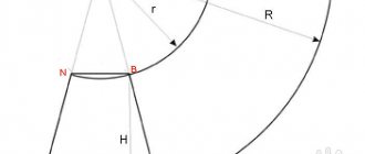
Fig.2 Machine structure
- Description:
- electrode;
- electrode clamp screw;
- positive wire clamp screw;
- guide bushing;
- fluoroplastic body;
- oil supply hole;
- tripod;
Body 6 is machined from fluoroplastic. The grounding pin of a 3-phase Euro socket is used as a guide sleeve 4 for electrode 1.
It was drilled along the axis to install an electrode into it, and two threaded holes were made to secure the electrode and wire. As the electrode evaporates, it is moved forward by loosening screw 2.
The entire structure is mounted on a reliable tripod, which allows you to change the height. A tube with oil is inserted into hole 6. Guide sleeve 4 supplies oil along the electrode like a syringe.
Fig.3 Photo of the machine
To drive the electrode, a domestic starter with a 220V coil was used, the rod of which has a stroke of 10 mm (it determines the maximum depth of the hole). The starter winding is connected in parallel with lamp H1, so while the capacitors are charging (the lamp is on), the starter rod is retracted.
After charging the capacitors, the lamp goes out because the current in the system stops flowing and the rod is released. When the rod is released, it touches the part, a spark discharge occurs, lamp H1 lights up and the rod retracts again. The cycle repeats again, with a frequency of approximately 1 Hz. If you need to increase the frequency, then you need to increase the power of lamp H1.
A file is used as a detail in the photo.
Fig.4 Photos of a drill with a hole made by this machine.
§6 Safety precautions during operation
- When working with the machine you need to consider:
- Firstly, due to the lack of the necessary transformer, the spark generator circuit was made without galvanic isolation from the 220V industrial network. If the part is somehow grounded, this will lead to a short circuit in the network.
- Secondly, due to the lack of the necessary transformer, a voltage dangerous to human life is used. A spark discharge at 220V 1000 uF will be lethal.
- Thirdly, electronic devices should not be connected to the part, even through the housing. For example, if you do not completely remove the electronic components from the car and disconnect the battery, you can easily damage them.
- Fourth, kerosene or oil supplied into the hole can easily ignite, leading to a fire.
Advantages of electric markers and their standard sizes
An electric marker for metal has a number of advantages over other devices for applying information to metal surfaces:
- the product is not subject to mechanical stress; it can be any thin-walled or complex configuration.
- Attention! The operation of the EM is relatively simple, but still requires a certain skill and careful preliminary calibration of the device
- the treated surface is not subject to corrosion and has a clearly visible matte finish.
- ability to work with various metals and their alloys: steel, titanium, zirconium, iron, copper, aluminum and many others.
- ease of removing the applied pattern - to do this, you just need to re-polish the metal in this place (since the depth of the holes does not exceed 1.5-2 mm ).
- comparative efficiency of the device - at maximum settings it consumes no more than 30-50 W.
- Possibility of long-term continuous operation of the EV - it has built-in overheating protection.
Most EVs have small overall dimensions (on average about 160x130x90 mm) and low weight (from 1,000 to 1,500 g)
CNC metal cutting portals
G_Kar 02 Mar 2020
We receive 793 parts per day. It takes a platoon of migrant workers with files to peel off so many small parts
Gesserk 02 Mar 2020
Today I found out that a machine that can handle such work should have a minimum power of 1 kW, ideally 1.5.
The cutting speed will be about 6m/min.
The length of the sweep contour is 55.70mm.
This results in an average of 10 parts per minute.
Post edited by Gesserk: 02 March 2020 22:53
Gesserk 02 Mar 2020
It takes a platoon of migrant workers with files to peel off so many small parts
After cutting, molding/stamping is required, then tumbling and galvanizing (tin/nickel plating).
Globul March 03, 2020
The length of the sweep contour is 55.70mm. This results in an average of 10 parts per minute. Then I see another problem - the table.
Where will these parts go? How to get them out of there?
G_Kar 03 Mar 2020
Globul , on a laser this is not a problem, they have drawers where small parts are poured. In the overall cost of the laser, this option is a trifle.
Gesserk 03 Mar 2020
Then I see another problem - the table.
Where will these parts go? How to get them out of there?
The parts, as planned, should be cut out in strips; there will be technological jumpers between them, which will be cut off during molding/stamping, so this is not a problem.
Post edited by Gesserk: 03 March 2020 09:02
mixasib 03 Mar 2020
Then I see another problem - the table.
Where will these parts go? How to get them out of there?
The table can be made with a sliding niche, as Oleg said.
The simplest and most common method that I have seen on the net from others is a mesh under the sheet supports. But it burns, alas. We make this
We have a water-filling table on our working plasma. It’s difficult to get small things - water treatments(
Some people have such a table that parts simply fall to the floor. Along with slag. Without any ventilation.
Today I found out that a machine that can handle such work should have a minimum power of 1 kW, ideally 1.5.
The cutting speed will be about 6m/min.
The length of the sweep contour is 55.70mm.
This results in an average of 10 parts per minute.
Is it 2mm thick? I'm not a pro, but I think you can try at a speed of 6000. Need to test.
You can watch the same hyper. The quality matches the price.
Post edited by mixasib: 03 March 2020 15:42
Gesserk 03 Mar 2020
You can watch the same hyper. The quality matches the price.
Can be more?
TIGER 19 Mar 2020
Globul March 19, 2020
Can be more? Most likely, this means equipment from Hypertherm, a world leader in this field.
welderman Mar 19, 2020
Then I see another problem - the table. Where will these parts go? How to get them out of there? But this is still a problem, the parts fall down, they are covered in grime, then there is fuss with cleaning. or you set the program so that you manually remove the parts from the table before they fall, but this is also a so-so solution.
The best models. How to choose
Currently, there are five EV models that are most common on the market. We present their characteristics in the table below.
| Model name | Manufacturer, Country | Size of the applied hole, microns | Maximum character size, mm | Operating voltage, V | Operating current, mA | Power, W | Average price, according to at the beginning 2022 |
| EVZ-021 | Josef Solnar (Czech Republic) | 10×10 | Up to 50 | 220…230 | 200 | 20 | 15000 |
| Progress-001 | (Russia) | 10×10 | Is not limited | 220…230 | 400 | 50 | 8000 |
| EVZ-022 | Josef Solnar (Czech Republic) | 20×50 | Is not limited | 220…230 | 450 | 50 | 20000 |
| AG25/3 | Arglo AG (Switzerland) | 20×20 | Is not limited | 4 | 5000 | 25 | 20000 |
| AG50/6 | Arglo AG (Switzerland) | 20×50 | Is not limited | 6,5 | 6500 | 50 | 25000 |
When choosing an EV, they are usually guided by the ratio of the parameters price - performance - maintainability. Therefore, in our country they usually choose a device produced in St. Petersburg - the Progress - 001 electric metal marker.