How to make a homemade metal milling machine
Many do-it-yourselfers dream of getting a variety of tools and devices in their arsenal, and especially a homemade milling machine for metal processing.
Such multifunctional equipment makes it possible to engage not only in the processing of metal products, but also wood. Such units have been used in the industrial sector for a very long time. Naturally, industrial machines are complex and multifunctional products, but a homemade milling device also allows you to perform many manipulations in the processing of metal and wood. If you have all the necessary tools and consumables, you can make such a device yourself, and quite quickly. The simplest unit is considered to be a vertical milling machine, assembled from improvised and, most importantly, inexpensive materials.
Device, types and characteristics
Structurally, a milling drill consists of a shank, a milling part and a drilling part. Products with two working surfaces are usually classified according to the following criteria:
- material (high-alloy tool high-speed steel, hard alloys);
- tail section designs (cylindrical, hexagonal);
- length of the shank (short, extended, long);
- the material being processed (for metal, wood, universal);
- manufacturing method (solid, composite);
- diameter (from 3 to 12 mm);
- overall length;
- length of working parts;
- hardness (61÷68 HRC).
A drill-cutter working on metal is a universal cutting tool. They perform operations to make shaped holes in any thin-walled material. The advantages of the product, firstly, include the fact that with the help of one tool it is possible to perform two operations, which reduces the time for making a hole of the required configuration. This fact increases labor productivity, which is a decisive factor in production. Secondly, to rotate the milling drill, you can use any tool that has an appropriate clamping device
This is important for home craftsmen and small workshops. They can use a hammer drill, drill, or tabletop drilling or milling machines
Thirdly, the product can be resharpened, i.e. the sharpening angle of the drill can be restored if it becomes dull.
Copy ring
CNC turning and milling machine for metal.
types and rating of the best In some cases, the copy sleeve is installed in one movement; in this case, alignment is not required.
There are other additional devices, but more on them later. Now let's talk about the copy ring - one of the mandatory attributes of a manual router, almost always included in the package. The device is very simple, but easy to use and useful.
Typically, this is a stamped steel plate with a raised ring around the center hole, which serves as a stop that tracks the copy template. The sleeve is selected for a specific cutter. Ideally, it should pass through the central hole with a small gap. In other words, you should not rely on the only ring that comes with the tool.
Most often, the bushing needs to be centered using a special cone. It is inserted into the collet (all the way to the copy ring), thereby leveling the position, and only then the mounting screws are finally tightened. Sometimes quick-release clamps are used instead of the latter, then there is no need to center anything.
The principle of operation of the equipment is simple - the protruding ring side in the center is guided along the template. In this case, the cutter follows the bends on the workpiece. The main “disadvantage” of such a “device” is one - it is impossible to get an exact copy - it will always be larger than the original.
This method is convenient in mass production (naturally, we are talking about household scales) or when the workpiece is valuable enough and it is worth making a template for its processing.
For precise and comfortable work, the router must have a smooth sole. When the copy sleeve is not in use, the groove intended for it is closed with a ring.
For precise and comfortable work, the router must have a smooth sole. When the copy sleeve is not in use, the groove intended for it is closed with a ring.
A similar bushing with the required diameter of the support ring is screwed on, but the mounting screws are not tightened.
For precise positioning of the bushing, a centering body is installed. It is clamped into a collet like a regular cutter (with the only difference being that the support sole is pressed against the body).
After installing the cone, the lowering mechanism stopper is released, and the sole, under the action of lifting springs, presses the cone to the bushing, thereby accurately centering it. Having secured the stopper again, the bushing fastening screws are securely tightened.
It is recommended to select a ring with the smallest possible diameter of the central hole, not forgetting that the working part of the cutter should pass through it freely.
If the template provides reliable support for only one side of the platform, an additional “support” is pulled out on the other and secured with a locking screw. If you don't do this, there is a high risk of losing exactly.
Adviсe
Let's talk a little about tips that should be taken into account when creating homemade cutter models.
- To give the cutting area the correct configuration, you will need to use diamond-coated needle files or angle grinders with discs that are used specifically for working with metal.
- The edge for cutting should be sharpened at a 7-10 degree angle. If you make it sharper, then it will hold an edge poorly, which is why its cutting properties will significantly decrease.
- If a wood cutter made by yourself must have some kind of complex device, you can flatten it or bend it.
- When using an edge router, take into account that the guide ring or bearing is already installed.
- The cutter must be secured in the collet before starting work.
- The presence of additional accessories will help increase the power of the electric tool.
- The part to be processed must have some kind of support.
- When carrying out work, the correct insertion depth level should be set.
- To prevent too much dust from being generated when working, you can use a vacuum cleaner.
In general, it should be said that creating a wood cutter yourself is not difficult. True, it should be understood that in this way you can quickly solve some simple problem, because for hardware such as bolts, ordinary steel is used, not tool steel. This means that such a homemade cutter will quickly wear out. But its life can be significantly extended in a number of ways.
Therefore, this solution has a place and should be used in cases where you really need to quickly acquire a pretty good wood cutter in order to get the desired result.
How to make a machine for metal?
How to make a wood milling machine with your own hands
When milling metal, high stress and vibration occur. The wooden frame will not support them. It is necessary to use a cast iron plate and a metal profile made of low carbon steel.
Option #1
The machine consists of:
- base;
- rack;
- slides with transverse movement guides;
- work table moving in the longitudinal direction;
- spindle head;
- stand with vertical guides;
- electric motor
https://youtube.com/watch?v=u2rbbCkZZnA
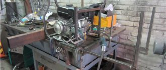
The cast iron base is leveled. A transverse dovetail groove is cut into it. A stand under the spindle carriage is attached to the rear part. The slide is inserted into a longitudinal groove. They move in the transverse direction due to the rotation of the screw. Ready made from a lathe will do. A table is installed on top. It moves along the figured slide guides. The tool moves vertically along with the carriage along the guides of the rack. A spindle head is installed on a massive plate in front, and a motor is mounted on the side. Both units are connected by a belt drive.
Option No. 2
Using an electric drill as a milling head, you can create a simple and lightweight model of a vertical milling machine.
- Make a base in the form of a frame from a profile pipe.
- Place a slide with a screw on it for longitudinal movement.
- A tool holder from a lathe with a cross screw and a vice are installed on top.
- There are 2 stands attached to the base. They are connected by 3 cross members for rigidity. The bottom one is at the base. The top 2 serve as support for the spindle carriage.
The drill moves vertically along the carriage guides. A rectangular metal profile is used to manufacture the machine. All connections are made with bolts. Due to 2 racks, the design is stable and durable.
Will need
We only need two M8 bolts and a washer with an outer diameter of 35-45 mm. By the way, the size of the bolt depends on the problem being solved. In our case, we select the future tool for a Forstner cutter to match the holes for a small ball bearing. It must be secured flush with the plane of the base. We will also make a clamp for pressing the element into the wood.
So, let's arm ourselves with power tools:
- Grinder (angle grinder) with cutting and grinding abrasive discs.
- Drill.
- Electric welding machine.
- Vertical drilling machine.
The hand tools we will need are: a file, a marker, and a caliper. Well, a workbench with a vice can be found in every workshop.
This is interesting: Making a stand for a drill with your own hands: instructions, drawings, video
Cutter with support bearing
The most elementary and compact device that sets the position of the machine is the cutter itself, if it is supplemented with a miniature ball bearing. It is located under or above the cutting knives and, accordingly, rests on the upper or lower edge of the edge. With the help of such equipment, shaped edges are obtained or grooves are cut for a connection, edging, seal, etc.
The advantages of the method include the ease of preparatory operations (you only need to adjust the vertical position) and the ability to accurately process rounded and curved edges (a typical example is a tabletop). The disadvantages follow from the advantages - it will not be possible to make a curve straight.
Guide rail
When it comes to straight lines, a guide rail is a good alternative to the rip fence. It is fixed at an arbitrary distance from the edge and at any angle to it. Instead of a stop, a special shoe is installed on the rods - it slides along the tire and sets the position of the router. Due to the support on the guide, a height difference may occur as the machine is raised above the workpiece. To avoid holding it suspended, extend the support leg (if provided).
In a special configuration, such guides also serve for precise milling of holes, which is especially important when making furniture (the ruler has holes with a standard pitch, the machine has a stopper; all you have to do is select the desired positions and drill).
Important note: a set of parts for working along the guide is not purchased in all cases; it must be included in the manufacturer's list of accessories and be suitable for the specific router. The tire is fixed relative to the workpiece
The router is positioned along it using a “shoe” similar to a side stop, and can be placed at different distances from it. Since only part of the platform rests on the tire, an additional “leg” is extended
The tire is fixed relative to the workpiece. The router is positioned along it using a “shoe” similar to a side stop, and can be placed at different distances from it. Since only part of the platform rests on the tire, an additional “leg” is extended.
How to make a wood lathe with your own hands: drawings and technology
The easiest way to make a tool yourself at home is to construct a lathe or milling machine from a drill or electric motor removed from another tool. This process is not that complicated, so every master can handle it. To do this, you will need an electric motor, the power of which does not exceed 500 W, and available materials. A drill can also be used as a drive. Of course, making a lathe will require some skill.
The device of the tailstock of a homemade wood lathe
To build the machine, the following elements are required:
- metal frame;
- electric motor;
- handyman;
- tailstock.
It wouldn’t hurt to get a drawing that will help you navigate the dimensions and correctly manufacture all the structural elements for its subsequent assembly.
How to make a homemade drilling machine with your own hands with a motor
First you need to prepare the electric motor shaft. To do this, a faceplate is installed on it; a steel center with a thread is also suitable. Installation of the second center is carried out in the tailstock tube. To make the frame, you will need a pair of corners measuring 5x3 cm, their length is 15 cm. A motor is attached to the frame using a bolted connection.
An example of a homemade drilling machine
At the next stage of making a homemade machine, you assemble the headstock yourself. This element is formed from a pair of horizontal and a pair of vertical corners. A pipe intended for the spindle is attached to it. You need to insert a bolt into it, the diameter of which is 1.2 cm. First, its head is sharpened at a right angle. Thus, the central part of the spindle is designated. After this, the headstock is installed on the bed. On the top post, which connects to the horizontal corners, it is necessary to secure the tube by welding.
To make a tool rest, you need to take a steel rod with a chamfer. This element must also have a hole that will be used to secure the support ruler. It is necessary to vertically weld the tube with the locking screw to the long angle. Then the tool rest rod is inserted into it.
The motor rotor on which the faceplate is attached will be used as the headstock spindle. You need to make several holes in it. A fork will be inserted in the central part. The holes along the edges are intended for fixing the part with screws.
Even with the help of simple tools you can create interesting wooden products; for this you need to study the technology of working with the tool and practice
How to make a wood lathe from a drill with your own hands
Having a workbench with a strong and flat working surface at hand, you can build a lathe without resorting to building a bed. The electric drill in this case will serve as a rotary drive and headstock. According to the simplest drawing of the machine, it is enough to fix this tool on the surface of the workbench through the neck. Clamps and a clamp are suitable for fixing.
Next you need to make a stop that will act as a tailstock.
This element is mounted opposite the drill. To create it, you can take two blocks of wood and an adjusting screw, sharpened at one end to a cone. If you intend to use the machine for processing massive wooden workpieces, then it is advisable to fix the stop on the table using clamps.
To make a tool with your own hands, inexpensive materials are enough. A drill-based lathe can be used to turn various parts:
- door handles;
- structural details of the staircase;
- decorative items, etc.
Using a workbench with a durable and flat working surface, you can make a lathe from a drill with your own hands
To expand the functionality of the tool, its design can be supplemented with attachments and other devices that can improve the quality of work.
Such improvements include:
- winding on transformers;
- applying a coloring composition over a rotating part to create patterns;
- applying spiral notches to the workpiece, etc.
Installing a special attachment in the form of a copier will allow you to use the machine to create a whole series of identical parts or products according to a template.
An example of a multifunctional homemade woodworking machine from a drill
This is interesting: Drill for a hammer drill - choice of impact-cutting attachment, its purpose
Manufacturing Features
A homemade part of this type has certain restrictions on the materials that can be worked with when using it. Creating cutters for a hand router usually involves working with steel, which belongs to the soft category.
For this reason, such a device allows you to work perfectly with wood, but if the material is very hard, then the effectiveness of the device is significantly reduced.
To create a homemade cutter, scraps of reinforcement or steel rods are usually used. Sometimes it is made from a drill. If the reinforcement is the base, then its ribbed coating will need to be leveled using a lathe.
First we need to make the shape of our future cutter.
- Using a pencil and ruler we draw knives. If the diagram is not at hand, then you can find examples on the Internet or in the relevant literature, then simply redraw the required profile and follow the further algorithm.
- Now you need to directly cut out the shape. Depending on how many knives we need as a result, it is necessary to count out the required number of sheets and, having grabbed them, carefully cut out the shape of the future product, without catching the pair of load-bearing sides of the knife, as well as the tip.
- After this you can start making the form. Using an adhesive composition, you will need to glue the template to the workpiece and carefully saw it off using a grinder. It is important to remember that not only the tip should be preserved, but also the side parts. So when working with an angle grinder you will need to be as careful as possible and take into account the dimensions of the product.
Cutting aluminum and how to get good results
Balance: A metal milling machine with a high feed rate and a very shallow depth per pass allows for good cooling of the cutter. It will pass through the aluminum alloy workpiece quickly enough to cool itself, but if the tool lingers too long (slow feed and deep depth per pass) in the same place, it will heat up and melt the cut on the workpiece due to friction. Keep in mind that almost any type of CNC router can successfully cut aluminum.
Consider this analogy: an adult can dig a hole quite quickly and shovel large amounts of sand at a time. A child can dig sand too, but only scratch the surface over and over again, and not take a full shovel. A child will eventually reach the same depth as an adult, but it will take a little longer.
Problem: A child does not use a shovel most effectively because the sharp tip of the shovel will dull faster than the top of the shovel, whereas an adult will work evenly with the entire shovel. The same is true with end mills. The deeper you can go through the workpiece with a router bit, the more evenly it will wear, extending its life.
So, what parameters must be met? This is an important question, because the result can cost a pretty penny. We have a good example. As already written above, a compact CNC metal milling machine and a vortex system are used to blow air through the cutter at a temperature of -50 degrees
The material being cut is grade 6061, which is a structural grade of aluminum, and its thickness is 5 mm, but it does not matter, since the cutting is carried out with a large number of passes. The thicker the material, the longer it will take to process, however, this is already clear
A Chinese spindle with a speed of 13,000 rpm is used for cutting. The feed rate (the speed at which the end mill moves through the cut) is set between 300 and 430 mm/min. Depth per pass is an important parameter that should be selected carefully. Onsrud, which has extensive experience in the face milling industry, recommends that the depth per pass be 1/2 the diameter of the cutter's cutter. For a 3 mm end mill, this is about 1.5 mm, but for finishing it is still better to take a depth equal to a quarter of the diameter of the cutting tool.
When cutting metal, vibration of the workpiece is the main problem that needs to be eliminated. At home, you can use a variety of fixation methods, ranging from clamps to a special vacuum table. No matter what clamping or clamping method is used, make sure that it will not move at all and that the clamp (screws, clamp) is as close to the cut as possible.
Let's sum it up
Based on the above, we can highlight the following points, remembering which it will become much easier to mill metal:
- Take your time. It’s better to spend more time on processing than to waste a mountain of expensive tools and ruin more than one workpiece.
- Use carbide cutters. They will serve for a very long time with correctly selected cutting conditions. And it is advisable to buy cutters from trusted manufacturers and in specialized stores.
- Use cutters with a smaller diameter. It is better to make more passes and get a beautiful cut place than to remove a kilogram of aluminum in one cut, throw away the “burnt” tool and see the torn edges of the workpiece.
- Don't be paranoid about cleaning the cut areas. There is no need to stand with a brush or vacuum cleaner over the workpiece you are processing; at the end, it is enough to simply sweep away all the waste or collect it with a magnet (if it is a ferromagnetic material).
- Lubricate the working tool with a mist of coolant. The “fog” effect is achieved by using a special fitting on the liquid supply pipe.
- Don't slow down the feed too much. If the feed is too slow, the cutter, instead of cutting the material, begins to rub against it and heat up very much, which leads to overheating of the tool and melting of the cut site (if the workpiece is made of a low-melting material).
- If your metal cutting machines do not feed fast enough, use fewer passes and increase the diameter of the cutter.
Step-by-step instruction
So, let's move on directly to considering the instructions for making the above-mentioned device.
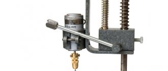
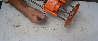
- First, use a caliper to measure the residual distance on the bolt head relative to the bearing being installed. If we are talking about an M8 type bolt, then the size of the hat circle in this case will be 1.27-1.3 cm. The diameter of the handle is about 1.16 cm, which makes it possible to easily clamp it in the vast majority of modern drill chucks.
- The cap should be adjusted to the bearing diameter. It is this area of the bolt that will represent the working part of the cutter.
- For marking, it is better to use a thinner contrast marker; the main thing is that the marks that will be applied with it are easily distinguishable on the metal. Now we apply the markings of the cutter's burrs. This solution will allow her to get rid of shavings without much effort.
- After this, we clamp the bolt in a vice. Using a cutting wheel, we use a grinder to create slits on the cap.
- We measure the bearing diameter. To work the head of a bolt with a faceted surface to a circle, you should transform the drill into a lathe. To do this, you need to clamp it in a vice, and then firmly attach the bolt in the chuck precisely in the center.
- Now you should fix the drill key at a constant operating mode, after which you can begin processing the bolt head. This process must be controlled at all stages of its implementation in order to prevent the center of the bolt from moving, which can cause a violation of the uniformity of the operated teeth.
- After this, you should install an abrasive disc on the grinder for grinding and process the edges around the circumference. The end area of the cutter should also be removed a little, leaving only a slight sharpness in the center. This element is of great importance, because this type of cutter will first find the center when working, and only then will the material be triggered by the rims and edges of the cutting type. Here you can carefully refine everything using a file, so as not to accidentally cut off more than is necessary during the grinding process.
- The cutter itself will be almost ready. All that remains is to give the cutting edges the required shape, and then sharpen them a little.
For greater efficiency, it would be useful to make the simplest clamp for pressing. Therefore, the instructions for creating it also need to be considered.
- This device is also made from an M8 bolt and a washer of suitable diameter. The bolt should be placed vertically on a surface made of metal so that the required contact for electric welding is ensured. The washer must be installed in the center of the bolt head. To make this job easier, you can use pliers. After this, the central part will need to be treated with an electrode to fill the area of the inner hole of the washer.
- Now you need to clamp the clamp, which was obtained as a result of the above actions in a vice, and then clean it using a grinder. You can walk along its back using a special brush attachment for a drill.
- At the final stage, all that remains is to install the finished device into the chuck of a vertical drilling machine, after which you will need to press the bearing into the wood. Such a simple “gadget” will eliminate a number of inconveniences when using a homemade cutter.
By the way, an end mill for wood can be made not only from a drill, but also from a tube with thin walls.
In this case, the algorithm for creating it will be as follows:
- in this case, the workpiece will be a piece of pipe with a length of about 20 centimeters;
- on the side where the cutting edge will be located in the future (somewhere at a distance of 2 cm from its intended location), oval-shaped grooves should be made on both sides of the pipe;
- the future cutting part of the cutter itself will need to be shaped into a cone - it is ground at an angle of about 2-3 degrees;
- when clamping the workpiece in a vice, a cross-shaped cut should be made at its end area - this can be done using an angle grinder;
- From the side of the cutting part, you need to make grooves on the workpiece - right up to the oval holes made earlier.
Required Tools
A very dense piece of cast iron or stainless steel is used to make the frame. A special shaft is attached to the caliper from above. Its upper zone rises above the table through an opening. In all such machines, the shaft lift height can be adjusted.
A spindle equipped with a cutting tool is mounted on top. Industrial models use a solid cutting arsenal. The key types of equipment are: disk, knife and cutters of various shapes.
To carry out cutting strictly along a straight vector, a special guide bar is used. Due to a special fastening unit, it moves to the desired length. The quality of processing increases significantly if the dynamics of spindle rotation is high.
Cutting disc for drill
If it is necessary to use an angle grinder, but it is not available, it is permissible to use a cutting wheel for a screwdriver or drill. To be able to use this device, you need to purchase or manufacture a special attachment that ensures reliable fastening of the cutting disc.
PHOTO: img.staticbg.com The cutting disc must be attached using a special adapter
Using a drill attachment for a cutting wheel has several advantages, including:
- the ability to process metal in places where it is difficult to reach with a regular grinder;
- versatility since the user only needs to change the attachment without having to change the tool.
PHOTO: Lower drill speed reduces metal cutting efficiency
The disadvantages of this method is the need to fully comply with safety rules when operating a cutting tool. Also among the negative aspects are:
- decreased operating efficiency due to fewer revolutions;
- limited thickness of the processed metal to 5 mm.
It must be taken into account that the shaft of the power tool can rotate in both directions. When cutting, you must ensure that its rotation is carried out exclusively clockwise.
PHOTO: ae01.alicdn.com A variety of cutting discs allows you to turn your drill into a universal tool
Active use of drill attachments allows you to significantly expand the range of applications of this tool, including use as equipment for plucking poultry or mixing a solution. Therefore, when carrying out construction or repair work, you need to think about the need to purchase such a device. You can once again learn about the features of nozzles for cutting metal from the presented video.
Watch this video on YouTube
PHOTO: beton-house.com The corresponding attachment turns the drill into a concrete mixer PHOTO: One movement, and you can pluck a bird with the drill PHOTO: A set of brushes will turn the drill into a device for cleaning and grinding metal
Previous DIY HomiusSpa at Home with Helpful Bath Bombs Next STORIESReinventing an Old Chair: 5 Creative and Easy Ideas
The operating principle of wood milling machines
Equipment in this category is intended for creating wood products. The technology is reminiscent of the work of a sculptor cutting off unnecessary parts of a shapeless blank. In this case, the main functions are performed by the cutter. This tool with sharp edges rotates at high speed, which speeds up work operations. It is driven by an electric motor. To ensure the required precision of movement, specialized mechanical devices are used.
Schematic diagram and kinematics
The drawing shows the design of a professional category machine. This example is suitable for studying typical functional components:
- To ensure precise manual movement of workpieces, special rulers (1, 5) and a multi-position sector (2) with teeth are used. These parts are fixed on the table (17).
- The limiter (4) prevents foreign objects from entering the work area.
- The remote control (6) is placed at a convenient access distance. The emergency power switch and other controls are placed here.
- The cutter (3) is installed on the spindle (12). It is reinforced with an additional upper support (7), which is inserted into the bracket (8). To lift this unit there is a special flywheel (9).
- The tension of the belt drive is adjusted using a handle (10) with a screw drive.
- The electric motor (11) is located at the bottom. The massive frame ensures stability in all operating modes.
- A separate flywheel (13) changes the height of the spindle. The switch (15) sets its rotation speed.
- The main switch (16) is installed on the side wall.
This design is designed for heavy loads. It is suitable for creating metalworking equipment. In this publication we are talking about wood milling machines, so it is permissible to use a less durable power frame and electric drives of relatively low power.
The cutter is installed in the spindle in the upward direction, the drive is in the lower part of the housing
This design with a wide and durable table is well suited for face processing of large workpieces. Work operations are performed manually, so rulers and other limiters are useful.
Vertical milling machine for wood (factory model)
This option ensures higher processing accuracy with the help of rigid fixation of the workpiece and built-in smooth movement mechanisms.
CNC wood router
This is the most expensive equipment with improved technical characteristics. Here, the spindle for a wood router moves along with the tool along a given path very accurately using stepper motors without intervention or careful control by the user. Ensures high processing speed without compromising quality. An additional advantage is the possibility of repeating the same technological processes many times.
Copy horizontal wood milling machine
In this design, the working unit is rigidly connected to the control probe, which limits its movement taking into account the shape of the sample. Using this not too complicated device, you can create high-quality copies in your home workshop.
For your information! If necessary, you can find instructions for creating homemade turning and milling machines for wood and other modifications. In any case, it is necessary to determine in advance the characteristics of future technological operations to clarify the parameters of suitable equipment.
Moving parts
Having finished connecting the engine and making sure that it normally increases and decreases speed, you can proceed directly to the circular device.
Let's figure out which moving units that bear the main load we will need:
- saw shaft,
- SMA motor shaft,
- drive belt,
- two pulleys - from the washing machine and the circular shaft.
The drive must operate in this manner. The engine transmits rotation to a shaft on which a small pulley is pressed. The last one is wearing a belt that sends revolutions to the second pulley. At first glance, everything seems simple, but when the circular is being installed, many difficulties arise that must be resolved.
The small pulley must be sharpened. Three to four transverse grooves are placed on it so that the belt has the opportunity for a good hook.
You don’t have to use the belt from an old washing machine; just take an analogue from another unit. The main thing is that it is durable and has teeth.
A disc of a slightly larger diameter is welded to the edge of the large pulley to create a protrusion that prevents the belt from slipping during operation. It is not necessary to sharpen the serrations on this pulley; the clutch with the belt will be quite sufficient.
The shaft holding the circular saw, fastenings in the form of a washer and a nut must be reliable so that at maximum speed the saw does not become deformed and does not jump off, injuring workers. It is recommended to use the shaft and fasteners from a factory-made circular saw.
The procedure for constructing a circular saw is described for a saw with a three-hundredth blade. Many will say that the SMA engine will not pull such a saw and will stop. But here you should remember a few rules:
- you need to be able to work correctly on a circular saw,
- household saw, designed to work with small volumes of materials,
- the successful operation of such a saw is confirmed by numerous reviews.
Simply put, the saw should not be overloaded, and it is better not to work at idle speed .
Homemade router: option No. 1
In fact, this model is a combination of a lathe and a drilling machine. From the first one the bed will be used. A coordinate table is installed on the guides, which will move along one axis. A support column is mounted in place of the headstock to install the milling head.
The electric motor is mounted separately so that its vibration does not affect the accuracy of operations. A tensioner is required at the top of the milling head. It is used to adjust the belt drive.
Features of self-production of a milling machine:
- the working head is shifted in the vertical plane using a worm gear;
- plate for installing workpieces with fastening grooves;
- installation of a lighting device to increase the accuracy of the work performed.
Using this milling machine, you can perform basic operations on processing metal workpieces. The disadvantage of the design is the lack of a rotating mechanism on the working head.
The simplest clamp for pressing
We will make this device from the same M8 bolt and a washer of suitable diameter. We place the bolt vertically on a metal surface, providing mass contact for electric welding. We place the washer on top in the center of the bolt head, holding it with pliers. We scald the center with an electrode, filling the area of the inner hole of the washer.
We clamp the resulting clamp in a vice and clean it with an angle grinder. The back part can be passed with a cleaning brush attachment for a drill.
We insert the finished clamp into the chuck of a vertical drilling machine, and try to press the bearing into the wood. This simple device will save you unnecessary effort and allow you to accurately handle such tasks.