A lathe is needed for the manufacture and processing of metal parts. Professional equipment is quite expensive, so in order to save money, you can make a homemade metal lathe with your own hands. This can be done in several ways, and drawings of such a product are easily found on the Internet. You can use improvised materials for production, but the size of the machine can be any.
A professional lathe is expensive, so it makes sense to make such a device yourself
Is it possible to do this?
Creating a spherical part on turning equipment is a simpler process than it seems at first glance. In this case, you can use both auxiliary equipment, if the production of a small batch is planned, and standard equipment of the machine in the case of piece production. The most affordable way is turning using a previously prepared template.
For metal
Working with metal is an order of magnitude more difficult compared to other materials due to its higher hardness, but it is more familiar and does not have unusual features. Turning a ball will take at least two passes and will require working at high speeds to obtain a satisfactory result. In general, the process is little different from other turning operations and has no specific specifics.
On wood
Compared to a metal workpiece, a wooden workpiece is more amenable to processing, which is why it is possible to carry out processing not only with a lathe cutter, but also with hand chisels and crowns intended for this operation.
When turning, instead of the usual shavings, wood dust remains, so you need to work strictly in a respirator, turning on the hood. It would be a good idea to remove oil spills on the machine in advance and install a vacuum cleaner on the tool holder, which will simplify cleaning after work.
Safety precautions when working with a homemade lathe
When working with the structure, certain safety precautions must be observed. So, after assembling the machine, you need to check its functionality. The spindle should rotate easily and without hesitation, with the front and rear centers aligned on a common axis. The center of symmetry of the rotating part must coincide with the axis of its rotation.
Any video of a do-it-yourself lathe shows that after installing the electric motor, it is covered with a special casing. The latter serves not only to protect the machine operator, but also to protect the motor itself from dust, metal particles and dirt. For a machine made on the basis of an electric drill, such a casing is not needed.
An example of a metal lathe, assembled by yourself
You should also adhere to the following safety rules:
Alternative methods for making a topiary base
Polyurethane foam
We squeeze the polyethylene foam into a plastic bag to get a blank - a figure close to the shape of a sphere, but definitely larger than the required diameter of the ball. We wait until the sealant has completely hardened, remove the bag, and use a utility knife to give the mass the desired shape - not just a ball.
DIY foam ball
Instead of polyurethane foam, you can use a foam blank, for example, packaging from household appliances, or glue several sheets together to obtain the required thickness.
But the foam is non-uniform and crumbles a lot: making a topiary ball of the correct shape is difficult, and a lot of debris remains. You can also cut a base for a flat topiary from a foam sheet.
Papier-mâché technique
We inflate the balloon to the desired size, coat the surface with PVA, glue sheets of paper (you can use toilet paper), fragments of old newspapers or napkins. We continue to increase the mass, generously coating each layer with glue, gaining a thickness of at least 7-10 mm.
After the workpiece has completely dried, carefully deflate and pull out the balloon; the frame remains. The result was a fragile but original ball for topiary using the papier-mâché technique. The method is labor-intensive, the base takes a long time to dry.
Knitting thread
The method exactly imitates the papier-mâché technique, but instead of paper, knitting threads are used: the result is a frame suitable for a light crown. We do not recommend using twine instead of yarn: the material is expensive and strongly absorbs glue.
Ready-made balls for the tree of happiness
Purchased blanks and improvised bases for topiary:
- Styrofoam ball. For the tree of happiness, it is advisable to use ready-made foam balls with a diameter of 7 to 30 cm.
- Hanging rattan. Ready-made rattan balls are available at decor stores. In addition, you can make them yourself (rattan is wrapped around a balloon).
- Rubber ball. Limited selection of trunks for topiary: only a cable is suitable, which must be attached to the outside of the ball.
- A ball of knitting thread.
- Chipboard is a die-cut made of thick cardboard. Blank for flat topiary on a magnet, thickness 1-3 mm.
- Tennis ball. For miniature trees.
- Ostrich egg. An original base for Easter topiary. Ostrich eggs are very durable and decor sticks well to the surface.
- Foam ball. Multi-colored products are used by magicians to perform tricks, but are also great for our purposes!
- Wooden ball. They are rarely used, but for a certain design a wooden base is optimal.
How to turn a cone on a lathe: diagrams, methods
How to turn a cone on a lathe
Lathes are used to turn workpieces during turning by using special cutters. If you have some experience, you can turn not only parts of a regular shape, but also, for example, a conical surface. To create a cone, you must have certain skills on a lathe.
Rotating the upper caliper slide
You can carry out the cone turning process using the following recommendation:
- We take the workpiece and secure it in the spindle, as well as the tailstock. Considering that the cone is manufactured with high precision, the diametrical size and angle may have slight deviations. If the workpiece is made of hard material, carbide cutters should be selected.
- Processing can only be carried out in compliance with safety precautions through the use of personal protective equipment.
- Selecting the cutting speed on the lathe. Machining of conical surfaces can be carried out at a speed that is selected depending on the durability of the cutting edge and the hardness of the material. If there is no exact data that allows you to calculate the cutting speed, you should follow the test path - from lower to higher values.
- The installed workpiece must be given a cylindrical shape. For this, a through cutter is used, first roughing is carried out to remove a large amount of unnecessary metal. Processing near the cams is carried out with a bent cutter.
- The production of precision parts occurs in two passes: roughing and finishing. On a lathe, finishing turning is carried out with a special cutting tool at a certain speed and feed.
- To create small conical surfaces, the top of the caliper is rotated at a certain angle, which should be equal to half the angle of the cone at the apex.
In a similar way, you can create conical surfaces without using a special device.
Method of displacement relative to the axis of centers
Shifting the centers also makes it possible to obtain a Morse taper on a lathe. However, in this case, turning can only be done on external conical surfaces. The advantages of the method under consideration include:
- It is possible to make a long Morse taper.
- A mechanical support feed is used, which makes it possible to use conventional models of lathes.
Center axis offset
Significant disadvantages include:
- Low precision with which the part can be made.
- In the process of obtaining a cone, the center holes become skewed.
The amount of displacement of the tailstock during the creation of conical surfaces is determined using a right triangle.
Cone ruler
Some lathes are equipped with special tapered rulers. Such a device allows you to process external and internal surfaces when the angle of inclination does not exceed 12 degrees. In this case, a cone shape can be made by combining longitudinal and transverse transmission.
When using a ruler, you can select the angle that will be created by simultaneously moving the caliper in the longitudinal and transverse directions. A special ruler allows you to maintain the correct angle throughout.
Using a wide angle cutter
A fairly simple way to obtain a tapered surface on a lathe is to use a corner cutter. With its help, you can create a cone of short length; the cutting edge should be straight. The angle of the taper can be adjusted by sharpening the edge or setting it at a specific angle to the workpiece.
Turning a cone with a cutter
All of the above methods require certain skills in operating a lathe. In some cases, for large-scale production, special copiers are made. For small-scale production, a method that uses a ruler or turning the lathe slide or shifting the headstock is suitable.
Information about the manufacturer of the screw-cutting lathe Umelets
Manufacturer of the table lathe Umelets (SN, SN-1) - Srednevolzhsky machine-tool plant SVSZ , founded in 1876.
The production of metal-cutting machines at the Srednevolzhsky Machine Tool Plant first began at the end of January 1926. The first machine produced at the enterprise was a screw-cutting lathe with a stepped pulley, model TV-155V.
In 1934, the plant created an original screw-cutting lathe, model SP-162 , with 8 speeds and spindle revolutions per minute from 24 to 482. For the first time, an individual electric motor with a power of 1.5 kW was installed on the machine.
During the war years, the plant mastered the production of a screw-cutting lathe 1615
and soon upgraded it, bringing the spindle speed to 1000 rpm.
In 1949, the machine was put into mass production 1616
, in the sixties the models were
1B616 and 1A616
, and from the beginning of the seventies the production of the
16B16 .
Since the 90s of the last century, the SVSZ company has been producing lathes under the SAMAT .
Machine tools manufactured by the Srednevolzhsky Machine Tool Plant, SVSZ, Samara
- 1A616
universal screw-cutting lathe, Ø 320 - 1A616k
screw-cutting lathe with automatic transmission, Ø 320 - 1A616P
high-precision screw-cutting lathe, Ø 320 - 1B811
turning and backing machine, Ø 250 - 1E811
turning and backing machine, Ø 250 - 1P611
universal screw-cutting lathe, Ø 250 - 16B16
universal screw-cutting lathe, 320 - 16B16A
especially high precision screw-cutting lathe, Ø 320 - 16B16KA
especially high precision screw-cutting lathe with automatic transmission, Ø 320 - 16B16P
high-precision screw-cutting lathe, Ø 320 - 16B16KP
high-precision screw-cutting lathe with automatic transmission, Ø 320 - 16B16F3
chuck center lathe with CNC, Ø 320 - 16B16T1
CNC lathe, Ø 320 - 16D16AF1
especially high precision screw-cutting lathe with digital display, Ø 320 - 561
thread milling machine, Ø 400 x 700 - 1615
universal screw-cutting lathe, Ø 320 - 1616
universal screw-cutting lathe, Ø 320 - 1716PF3
CNC lathe, Ø 320 - 5350A
semi-automatic slot milling machine, Ø 150 - Samat 400
high-precision screw-cutting lathe, Ø 400 - Craftsman
table lathe, Ø 175
Turner services
Finding someone who will provide turner services in Moscow is not very easy. There are fewer and fewer good turning specialists left, as young people do not go to study for blue-collar jobs. Turning works photo. We are proud that we have excellent turners in our team. Before answering your question about the cost of turning services, we need to know from you:
- drawing or drawing with exact dimensions (or sample part) (can be sent by email
- type of material processed and type of work required
- required quantity
- material for work, yours or ours
- other recommendations and wishes.
We try to fulfill all orders on time and with high quality. Our prices are quite affordable. Turning works in Moscow.
metal turning works master turning works price
TURNING SERVICES. Turning work photo
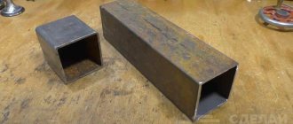
Despite the presence of many methods of forming processes (casting, powder metallurgy, etc.), cold metal working is widespread in the engineering industry.
Very often it is simply unprofitable to produce special casting molds and purchase equipment. Or the only way to make a part is from a piece of metal (plate, rod, profile).
Craftsman (SN, SN-1) Tabletop screw-cutting lathe. Purpose, scope
Screw-cutting lathes of the Umelets (SN, SN-1) are designed to perform a variety of turning operations, including cutting metric threads. Accuracy class N according to GOST 8.
The table-top screw-cutting lathe "Umelets" is designed for various types of mechanical processing of metal, wood, and plastic products. The machine is manufactured in 2 versions: with manual longitudinal feed of the caliper without additional devices and with feed drive, with milling and woodworking devices. On the first version of the machine you can perform turning and drilling work.
On the second version of the machine, you can perform turning, milling, drilling, planing, and sawing operations.
With the help of simple devices made on this machine by the consumer himself, other work can be performed. The “Unelets” machine can be used in domestic conditions for the manufacture of various household products, in school workshops, in circles at pioneer clubs and docks, and at stations for young technicians.
Umelets table-top screw-cutting lathe is a small machine and is designed for processing small-sized workpieces:
- The largest diameter of the “disk” type workpiece above the bed is Ø 175 mm
- The largest diameter of the “shaft” type workpiece above the caliper is Ø 90 mm
- Center-to-center distance (RMD) - 215 mm
- Through hole in the spindle for processing rods - Ø 15 mm
- Power of the asynchronous electric motor of the main movement - 0.55 kW
- Machine weight - 90 kg
spindle receives 12 stages of forward and reverse (160..3150 rpm) rotation speeds. The spindle rotation speed is determined by the position of 2 V-belts on three pulleys:
- Feed pulley - 4-speed pulley on the electric motor shaft;
- Take-up pulley - 4-speed pulley at the end of the spindle;
- Intermediate - 5-speed pulley on a moving axis.
The front end of the spindle is threaded M27 x 2.5 mm.
- Internal (tool) spindle cone - Morse 2
- The standard diameter of the lathe chuck is Ø 80 mm (Chuck 7100-0001 GOST 2675)
- Switching the direction of spindle movement - reverse the electric motor
The feed drive (machine model CH-01) receives movement from the gear on the spindle and transmits it to the lead screw. The feed drive consists of 5 gears - one permanent, coupled to the spindle, and 4 replaceable (guitar).
The choice of the mechanical feed speed and the pitch of the thread being cut is carried out by rearranging the replaceable gears of the guitar in the feed drive. The feed drive provides:
- Cutting 16 metric threads in the range - 0.02..2.5 mm
- Longitudinal feeds - 6 steps - 0.05; 0.075; 0.1; 0.125; 0.15; 0.75 mm/rev
The lead screw is turned on and off by a jaw clutch and is used both for thread cutting and for mechanical feed of the slide during turning.
Turning with fixture
A more complex way is to turn a ball on a machine using a pre-fabricated fixture. Due to the ideality of the spherical surface, the manufacturing accuracy of the mechanism must be maximum. In the following proposed video, the device is manual, and the processing is partially performed after preliminary turning with cutters to a shape close to a ball:
A special feature of this method of turning spheres is that it can only be used when processing soft metals. But this task is quite common, and with a large number of orders, such a device can always help the turner.
Step-by-step instruction
This manufacturing method is suitable for both metal and wood. Additional machine equipment and non-standard designs are not required. All you need is a sample. As such, you can use a machine-turned ball with a rod or a ball from a bearing of the required diameter.
To be able to install the latter, you need to rigidly attach a shank rod of the required diameter exactly in the center to it. This can be done by welding or threaded connection.
Workpiece selection
In both cases, the workpiece must have a cylindrical shape with a margin (approximately 1/10) of length for fastening in the chuck and a small allowance for processing along the width. If steel rod is a standardized material in metallurgy, then for carpentry work most often the raw material is supplied in the form of timber. Before starting work, you need to give the material the shape of a cylinder, secure it in a driving chuck and grind it.
Important!
Before starting work, visually check the workpiece for curvature by rotating it in the jaw chuck.
Create a groove
The diameter of the ball is equal to the diameter of the grooves and the distance between them. Clamping the workpiece in a three-jaw chuck, machine the future part at a given distance from the end. The created groove will serve as a kind of mark when processing using cross feed. It is also necessary to countersink the hole for subsequent fixation in a rigid center when processing the workpiece with abrasive.
Carry out fixation
Now, using a rigid center installed in the tailstock and a chuck, we fix it. Having loosened the chuck with a key, we place the workpiece in it. Now you need to make an indent from the groove and securely secure the part in the chuck. The template must be secured in the tailstock. Having verified the required distance and position of the workpiece relative to the sample, you can proceed to the next step.
Turn using front feed
To give the workpiece a ball shape, it is necessary to use two identical cutting tools, usually with a rounded cutting edge. Attach the cutters to the caliper holder on one side with the same offset.
The essence of the method is to guide the copy cutter touching the circumference of the spherical sample, while the mirror-mounted cutter grinds the workpiece, repeating the vector of movement of the second one.
Turning is carried out by direct and transverse feed, as a result of which a surface in the form of a ladder is formed. After shaping the material into a ball, a finishing pass is made with a small thickness of the layer being removed and feed. Removal of layers of material is carried out within the groove. After which it must be removed, combining the transverse and front feed.
Make a shape using a file
After processing with a cutter, a stepped surface is formed, which must be processed with a file. For metal, you should choose a file with a cut number 0 or 1. For wood, with a simple single cut. A tool with a semicircular working part will greatly simplify the process, but is not a prerequisite. It is advisable to use a support without a cutter as a stop; it will serve as a reliable support and reduce the likelihood of injury.
We install the caliper platform at the level of the part before the operation. Having removed the sample, we bring the rigid center to the hole previously created with a countersink, moving the headstock forward and fixing it. We start the machine at minimum speed, waiting for the spindle to pick up speed. We rest the shank or handle of the file against the support and, with a smooth movement from top to bottom, lower the working part of the file to the workpiece.
In this case, you need to hold it firmly with both hands on both ends of the tool to prevent the tool from hitting. If you are using a flat file, you must move it smoothly from edge to edge for uniform processing.
Important!
Move the file opposite to the movement of the spindle to prevent the tool from kicking back.
Clean with sandpaper
When finishing, use sandpaper. Each material will require a different grit of abrasive. For metal in the region of P800-P1000, for wood P400-P600. There are two ways to polish a surface using an abrasive belt. In the first case, the canvas is stretched with both hands and pulled onto the surface to be treated; in the second, the sandpaper is attached to a special block.
The raw ends used for fastening are removed by hand. As you can see, manufacturing a part in the form of a ball is a completely easy and feasible task, without requiring highly complex add-ons on current equipment.
Technical characteristics of the Umelets machine
| Parameter name | CH | CH-1 |
| Main settings | ||
| Accuracy class according to GOST 8-82 | N | N |
| The largest diameter of the workpiece above the bed, mm | 175 | 175 |
| The largest diameter of the workpiece above the support, mm | 90 | 90 |
| Maximum workpiece length (RMC), mm | 215 | 215 |
| Maximum cutter height, mm | 10 x 16 | 10 x 16 |
| Spindle | ||
| Diameter of through hole in spindle, mm | 15 | 15 |
| Maximum rod diameter, mm | 14 | 14 |
| Number of speed steps for direct spindle rotation | 12 | 12 |
| Spindle direct rotation frequency, rpm | 160..3150 | 160..3150 |
| Size of the internal cone in the spindle, M | Morse 2 | Morse 2 |
| Threaded spindle end | M | M |
| Caliper. Submissions | ||
| Maximum longitudinal stroke length of the carriage, mm | 215 | 215 |
| Price for dividing the longitudinal feed dial, mm | 0,5 | 0,5 |
| Maximum transverse stroke length of the carriage, mm | 90 | 90 |
| Transverse feed dial division price, mm | 0,05 | 0,05 |
| Number of longitudinal feed stages | ||
| Limits of longitudinal feeds, mm/rev | No | 0,05..0,175 |
| Transverse feed limits, mm/rev | No | No |
| Speed of fast movements of the caliper, longitudinal, m/min | No | No |
| Number of metric threads to be cut | ||
| Limits of pitches of cut metric threads, mm | No | 0,2..2,5 |
| Movable tool holder (Cutter slide) | ||
| Cutting slide dial division price, mm | 0,05 | 0,05 |
| Maximum movement of the slide, mm | ||
| Maximum angle of rotation of the cutting slide, mm | ±90° | ±90° |
| Tailstock | ||
| Dial division price, mm | No | No |
| Quill inner cone size | Morse 1 | Morse 1 |
| Maximum movement of the quill, mm | 40 | 40 |
| Transverse displacement of the tailstock housing, mm | No | No |
| Electrical equipment | ||
| Supply voltage, V | ~220 V | ~220 V |
| Number of electric motors on the machine | 1 | 1 |
| Main drive electric motor power, kW | 0,55 | 0,55 |
| Dimensions and weight of the machine | ||
| Machine dimensions, mm | 770 x 460 x 360 | 770 x 460 x 360 |
| Machine weight, kg | 85 | 90 |
- Universal tabletop machine “Craftsman” SN, SN-1. Operating manual SN.000.000 RE, 1991
- Acherkan N.S. Metal-cutting machines, Volume 1, 1965
- Batov V.P. Lathes, 1978
- Beletsky D.G. Handbook of a universal turner, 1987
- Denezhny P.M., Stiskin G.M., Thor I.E. Turning, 1972. (1k62)
- Denezhny P.M., Stiskin G.M., Thor I.E. Turning, 1979. (16k20)
- Modzelevsky A. A., Muschinkin A. A., Kedrov S. S., Sobol A. M., Zavgorodniy Yu. P., Lathes, 1973
- Pikus M.Yu. A mechanic's guide to machine repair, 1987
- Skhirtladze A.G., Novikov V.Yu. Technological equipment for machine-building industries, 1980
- Tepinkichiev V.K. Metal cutting machines, 1973
- Chernov N.N. Metal cutting machines, 1988
Bibliography:
Related Links. Additional Information
- Classification and main characteristics of turning
- Selecting the right metalworking machine
- Multi-start thread. Methods for cutting multi-start threads on a lathe
- Graphic signs for lathes
- Friction clutch of a screw-cutting lathe
- Lathe repair technology. Repair of bed and support guides
- Lathe repair technology. Repair of headstock and tailstock
- Lathe spindle repair
- Methodology for checking and testing screw-cutting lathes for accuracy
- Directory of lathes
- Manufacturers of lathes
Home About the company News Articles Price list Contacts Reference information Interesting video KPO woodworking machines Manufacturers
Is it possible to do this?
Creating a spherical part on turning equipment is a simpler process than it seems at first glance. In this case, you can use both auxiliary equipment, if the production of a small batch is planned, and standard equipment of the machine in the case of piece production. The most affordable way is turning using a previously prepared template.
For metal
Working with metal is an order of magnitude more difficult compared to other materials due to its higher hardness, but it is more familiar and does not have unusual features. Turning a ball will take at least two passes and will require working at high speeds to obtain a satisfactory result. In general, the process is little different from other turning operations and has no specific specifics.
On wood
Compared to a metal workpiece, a wooden workpiece is more amenable to processing, which is why it is possible to carry out processing not only with a lathe cutter, but also with hand chisels and crowns intended for this operation.
When turning, instead of the usual shavings, wood dust remains, so you need to work strictly in a respirator, turning on the hood. It would be a good idea to remove oil spills on the machine in advance and install a vacuum cleaner on the tool holder, which will simplify cleaning after work.
How to turn a cone on a lathe
Lathes are used to turn workpieces during turning by using special cutters. If you have some experience, you can turn not only parts of a regular shape, but also, for example, a conical surface. To create a cone, you must have certain skills on a lathe.
Taper turning
Rotating the upper caliper slide
You can carry out the cone turning process using the following recommendation:
- We take the workpiece and secure it in the spindle, as well as the tailstock. Considering that the cone is manufactured with high precision, the diametrical size and angle may have slight deviations. If the workpiece is made of hard material, carbide cutters should be selected.
- Processing can only be carried out in compliance with safety precautions through the use of personal protective equipment.
- Selecting the cutting speed on the lathe. Machining of conical surfaces can be carried out at a speed that is selected depending on the durability of the cutting edge and the hardness of the material. If there is no exact data that allows you to calculate the cutting speed, you should follow the test path - from lower to higher values.
- The installed workpiece must be given a cylindrical shape. For this, a through cutter is used, first roughing is carried out to remove a large amount of unnecessary metal. Processing near the cams is carried out with a bent cutter.
- The production of precision parts occurs in two passes: roughing and finishing. On a lathe, finishing turning is carried out with a special cutting tool at a certain speed and feed.
- To create small conical surfaces, the top of the caliper is rotated at a certain angle, which should be equal to half the angle of the cone at the apex.
In a similar way, you can create conical surfaces without using a special device.
Method of displacement relative to the axis of centers
Shifting the centers also makes it possible to obtain a Morse taper on a lathe. However, in this case, turning can only be done on external conical surfaces. The advantages of the method under consideration include:
- It is possible to make a long Morse taper.
- A mechanical support feed is used, which makes it possible to use conventional models of lathes.
Center axis offset
Significant disadvantages include:
- Low precision with which the part can be made.
- In the process of obtaining a cone, the center holes become skewed.
The amount of displacement of the tailstock during the creation of conical surfaces is determined using a right triangle.
Cone ruler
Some lathes are equipped with special tapered rulers. Such a device allows you to process external and internal surfaces when the angle of inclination does not exceed 12 degrees. In this case, a cone shape can be made by combining longitudinal and transverse transmission.
https://youtube.com/watch?v=HysW_hx6pZ0
When using a ruler, you can select the angle that will be created by simultaneously moving the caliper in the longitudinal and transverse directions. A special ruler allows you to maintain the correct angle throughout.
Using a wide angle cutter
A fairly simple way to obtain a tapered surface on a lathe is to use a corner cutter. With its help, you can create a cone of short length; the cutting edge should be straight. The angle of the taper can be adjusted by sharpening the edge or setting it at a specific angle to the workpiece.
Turning a cone with a cutter
All of the above methods require certain skills in operating a lathe. In some cases, for large-scale production, special copiers are made. For small-scale production, a method that uses a ruler or turning the lathe slide or shifting the headstock is suitable.
If you find an error, please select a piece of text and press Ctrl+Enter.
Craftsman Location of controls for a screw-cutting lathe
Location of controls for a screw-cutting lathe Umelets
Craftsman Specification of controls for a screw-cutting lathe
- Feed movement control handle (turn on mechanical longitudinal feed of the caliper and turn on the feed)
- Spindle activation handle (direct - spindle rotation counterclockwise, reverse - spindle rotation clockwise)
- Handwheel for moving the tool holder
- Quill clamp handle
- Handwheel for moving the quill
- Handwheel for manual longitudinal movement of the caliper
- Handwheel for transverse caliper movement
- Electrical power switch
- Lamp indicating that the machine is connected to the mains
Using a special design
The process can be significantly simplified by using a special design. The device with which the work in question can be carried out allows you to rotate the cutter along a given circle. In this case, the following nuances can be noted:
- The structure must be rigidly fixed, for which you will have to make holes in the frame for its fastening.
- The metal is also pre-processed in a standard way using longitudinal-transverse feed.
- The design features of the design limit the minimum and maximum diameter of the resulting ball.
- In this case, you will also have to use emery to remove metal at the attachment point.
- The entire surface, except for the attachment point, is processed at one time. Pre-treatment for metal removal is necessary because in this case the cross feed is not adjustable (the diameter of the part is adjusted by the distance at which the cutting edge is located from the attachment point).
- The correct shape is achieved without the need for special processing skills.
- You can get a batch of spherical parts that will have the same dimensions.
In conclusion, we note that such a device is often created by hand. Lathes of older models are not suitable for automating the production process of producing spherical bodies.
If you find an error, please select a piece of text and press Ctrl+Enter.
Craftsman Location of the components of a screw-cutting lathe
Location of the components of the Umelets lathe
List of components of a screw-cutting lathe Umelets
- SN.010.000 - Base
- SN.015.000 – Main motion drive
- SN.020.000 – Spindle assembly
- SN.030.000 — Caliper movement mechanism
- SN.031.000 — Feed drive (only for SN-1)
- SN.033.000 – Caliper
- SN.040.000 - Rear headstock
- SN.070.000 – Casing
- SN.071.000 – Fencing
- SN.080.000 – Electrical equipment
DIY lathe headstock
The headstock for a lathe can be made independently without any problems.
For this purpose you will need:
- Wooden plank.
- Plywood, ten millimeters thick.
- A thin sheet of metal that is cut with special scissors.
It is much easier to make a headstock with your own hands if the basis of this device is an ordinary unnecessary drill. After this, it will only be necessary to make a stand, which will subsequently be the mounting platform for the drill, which has a strict horizontal axis.
The middle of the front and middle of the tailstock must be securely fastened, this is extremely necessary. For the tailstock, it is necessary to establish in advance the limits of the possibilities of wrapping along the axis and rigidly securing it in place.
The power of the electric motor should be selected independently, based on the purpose of the turning device. Although the engine power does not need to be less than 250 W. Otherwise, it will not be possible to turn out any necessary parts.
Craftsman General view of a screw-cutting lathe
Photo of a screw-cutting lathe Umelets
Photo of a screw-cutting lathe Umelets
Photo of a screw-cutting lathe Umelets
Photo of a screw-cutting lathe Umelets
Photo of a screw-cutting lathe Umelets
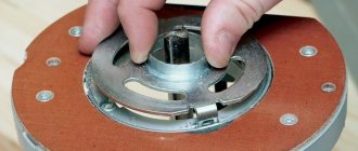
Do-it-yourself ball for a lathe
Here is one of the links to the balloon that I liked. » >
Damn, this is even more interesting than proxon, here you just need to make equipment for replaceable plates
Aspirant wrote: Damn, this is even more interesting than proxon,
Much more interesting. That's where else to find time to make it.
I have a designer part-time. While he is busy, how he will free himself (by the end of September from the gardens) is a mystery. then at the factory or I’ll create it myself
Aspirant wrote: I have a designer part-time
It’s good for you, but I’m my own Petlyura. And a designer, and a draftsman, and a mechanic, and a turner, etc.
Yes, I’m just like that, I just realized that I can’t do everything myself, so I’m turning to pensioners because they are an order of magnitude more experienced, wiser and smarter than us young people in everything. only we are nimble and that’s what makes us different
I can’t say this about myself.
Aspirant wrote: On Wednesday I received a little ball I’m thinking of adapting it to a Corvette or making an analogue for a large machine, I’m bragging
If possible, give the dimensions of this device. Here's a video about the spherotochka Here's more
At the request of the workers, I am developing the topic and posting drawings of the balloon I bought. Request to comrades who are at the chipmaker - make links to this topic, I want to encourage people to benefit the cause
and this is a photo of the glands themselves
And here is the assembled ball in position for turning external spheres
And now the main thing is that without a rectangular support, the cutting point coincides with the axis of rotation of the workpiece on the Corvette 400 when installing the equipment instead of a tool holder
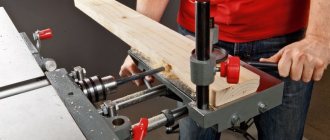
We make a wood milling machine for a home workshop
Milling machines are necessary for working with shaped wood parts. They are used for flat milling and profile processing. Professional equipment is multifunctional and costs a lot of money, so more and more “homemade” people are assembling such equipment for workshops and garages on their own.
Small DIY milling machine
The set of homemade wood milling machines includes:
- Drive mechanism. This is an engine whose power ranges from 1-2 kW. With such a motor, you can use various tools to work with wood without fear of failure.
- Lift for adjustment. Typically, it includes a body, sliding skids, carriages, a fixing screw and a threaded axle. During operation, the carriage moves up and down, and a screw is needed to fix it at the required level.
- Support. The table is made from solid wood.
Before assembly, be sure to draw up a detailed drawing with all dimensions. For manual wood milling machines, you need to think through everything in advance down to the smallest detail.
3D model of a table for a manual machine Equipment components Dimensions of the working element Cutting on a milling machine
The sequence of self-assembly of a convenient and practical wood milling machine for a home workshop is described in the video instructions:
If you are thinking about buying your own equipment rather than assembling it yourself, then to understand how much a manual wood router costs, look at the table with models and prices:
| Model name | Specifications | |
| Milling table Kraton MT-20-01 | site size | 64 by 36 cm |
| possibility of vertical work | There is | |
| equipment weight | 15.7 kg | |
| Milling table Kraton MT-20-01 | ||
| Milling machine Corvette-83 90830 | engine power | 750 W |
| transmission type | belt | |
| spindle speed | 11,000 rpm | |
| vertical stroke | 2.2 cm | |
| spindle diameter | 12.7mm | |
| Milling machine Corvette-83 90830 |
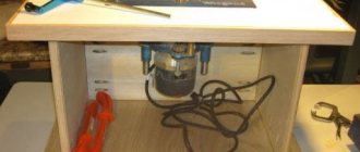
Making a CNC milling machine with your own hands
You can make your own numerical control equipment with your own hands. To do this, select suitable drawings of a CNC wood milling machine. You will need to assemble the model with your own hands strictly according to them.
Ready-made machine for a home workshop Equipment components Detailed assembly diagram Model of multifunctional equipment
Wood milling machines must have great strength, so it is better to take a rectangular beam mounted on guides as a basis. The lifespan of home equipment and its performance depend on proper assembly. Watch the video instructions for making such a device:
Below are photos of finished models of CNC woodworking machines with your own hands from professional “homemade” ones:
Kinematic chains
In the main movement drive circuit, the rotation of the spindle 14 is carried out from the electric motor 1 through V-belt drives and step pulleys 2, 3, 4. In the feed drive circuit, rotation from the spindle 14 to the lead screw 8 is transmitted through gears 5, 6, a set of interchangeable wheels A, B , B, D, D and claw coupling 13.
Main drive
The drive consists of an electric motor 1 (see Fig. 4), mounted on a bracket 2 and three stepped pulleys 3, 4, 5; The tension of the belts and the change in the center-to-center distance between the pulleys when transferring the belts to other pulley tracks is carried out by moving the pulley 4 mounted on the movable support 6. The drive allows you to obtain 12 operating speeds of the spindle from 160 to 3150 rpm.
Spindle assembly
The spindle assembly (Fig. 5) consists of a spindle 1, the supports of which are two angular contact bearings 2 installed in flanges 3. The flanges are mounted in the base housing. A three-jaw chuck 4 is fixed at the front end of the spindle; a gear wheel 5, which transmits rotation to the feed drive, and a V-belt pulley 6 are fixed at the rear end.
Drive chuck
The driving chuck included in the machine kit is placed in the accessory box. The driving chuck (see Fig. 6), installed instead of a three-jaw chuck and used for processing parts in centers, consists of a thrust center 1 inserted into the conical hole of the spindle, a nut 2 screwed onto the front end of the spindle and a driver 3.
Caliper movement mechanism
The mechanism (see Fig. 7) consists of a lead screw 1, at the straight end of which a flywheel 3 with a dial 2 is attached. The other end of the screw is connected by a coupling 4 to a shaft 5 mounted in angular contact bearings.
Feed drive
The feed drive (Fig. 8, 9, 10), which moves rotation from the spindle to the lead screw, consists of gear 1 (see Fig. 8), replaceable gears 2, 3, 4, 5, cam coupling 6, 7 .
By turning handle 1 (see Fig. 10), attached to the z-axis, clockwise, we move lever 3 with nut 4 and engage the jaw clutch, thereby turning on the caliper feed. Turn the handle counterclockwise to turn on the caliper feed. The transmission option shown in Fig. 8 is used for feeding during conventional turning; in Fig. 9 - for cutting right-hand threads, in Fig. 19 - for cutting left-hand threads. 5.10, Caliper.
The support (see Fig. 11) is designed to feed the cutting tool. The longitudinal feed of the caliper is carried out manually by the caliper moving mechanism or automatically by the feed drive.
When the lead screw rotates, movement is transmitted to carriage 2 through nut 1. Transverse feed of slider 6 is carried out manually by rotating handwheel 3 through screw 4 and nut 5.