A circular saw is a device that is used mainly in industry, but you can find people using it in private home settings. Some people try to make it themselves. The most important part here is the shaft. Most often, the shaft for the circular is made to order. To do this, you need to contact only a highly qualified turner. Fortunately, it’s not difficult to find something like this today. However, such work will be quite expensive. There are alternative methods to solve this problem. The easiest way is to create a shaft for a circular saw with your own hands. Of course, this requires a lathe.
Circular shaft drawing.
It is even possible that it will be numerically controlled. You will have to acquire some additional tools. You can't do without materials here.
Rolling machine
Non-table rollers externally resemble a two-roll stand of a rolling mill.
They differ from their factory counterpart not only in size, but also in capabilities - due to the installation of replaceable tools. Using cylindrical rollers with shaped grooves, you can produce wire of a wide variety of sections; round, triangular, square, diamond-shaped. Rollers with symmetrically located ridges and grooves are convenient for straightening (rolling stiffeners) metal plate parts. And by installing instead two steel disks with sharpened conical edges, it is easy to cut sheet materials - from paper to stainless steel 0.5 mm thick. Even the gears of the roller drive mechanism are used to form wavy parts: wire zigzags or corrugated plates. Rolling a wire ring or a cylindrical sleeve on this machine is also not difficult: it is enough to have a pair of cylindrical rollers of the appropriate diameters and, when rolling, press the workpiece with a wedge against one of them.
Tabletop rolling rollers are arranged as follows. The base, top plate and two side posts are made of thick steel beams. Using four M10 screws and four M10 bolts, they are connected into a strong supporting frame-cage. The upper and lower rollers are machined from 0 50 mm steel rod and hardened to obtain high surface hardness. Bronze bushings-bearings of the lower roller are mounted in the holes of the racks, and of the upper one - in sliders that can move along the vertical guides of the grooves of the racks.
From below, the sliders are pressed by small springs, which tend to push the rollers apart; from above, their movement is limited by stops installed in the threaded holes of the upper plate. The synchronous rotation of both stops, necessary for the parallel movement of the upper roller, is ensured by a gear drive mounted on the upper plate of the frame. It is formed by a wide regulator gear wheel, loosely mounted on an axis pressed into the center of the plate, and two narrow gears mounted through keys on the shanks of the stops. By turning the handle attached to the central wheel, you can change the position of the stops and at the same time the size of the working gap.
The rollers are driven into rotation by a handle placed on the square shank of the lower roller. The rotation is transmitted to the top using a gear transmission. This not only makes the rollers more efficient, but also allows the design to be used for cutting sheet metal using circular knives mounted on their axis.
Assembling the rollers consists of connecting the frame elements and parallel installation of the rollers. To perform additional operations, there is no need to disassemble the machine: the tools are quickly mounted in a cantilever on the shanks of the roller axes. For this purpose, they are provided with axial holes with MB threads, and on the outside - keys for transmitting rotation. Disc knives are also mounted on threaded mandrels there. If you need to cut a strip more than 35 mm wide, use an extended mandrel, which will move the knives away from the rack at a greater distance.
Source
Manufacturing process: step-by-step instructions
Marking the place where the saw is attached to the table
Marking and fastening of stiffeners
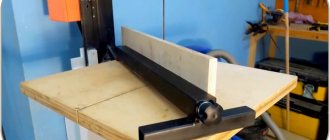
Tabletop for a circular saw in finished form
To make a quality structure, you need to follow some tips. The process consists of several steps presented in the table.
| Steps | Description |
| 1 | The block should be leveled on all sides using a plane. Then the frame of the future table is assembled from it. Several 5 mm holes need to be drilled in each side of the tabletop. Additionally, one through one is made for the legs of the product. |
| 2 | The drawers have several holes of the same diameter. In the legs one through one is made. The diameter remains the same, 5 mm. |
| 3 | Proceed to install the dowels into the tabletop. Before this, they are coated with wood glue. The legs and drawers are placed on top. If there are clamps with ties, the product should be secured using them. When the glue has completely dried, you need to fasten the drawers and legs using special metal fasteners. Additionally, it should be tightened with self-tapping screws. You can add reliability and strength to the structure by using corners. They will become an element of additional fastening and give the product stability. For the short side, 2 pieces are enough, and for the long side, 3 are suitable. |
| 4 | The next step involves securing the saw to the product from the inside. There are several methods to accomplish the task. M4 bolts or bars with self-tapping screws are suitable for fastening. The first case is fast and reliable. The second method does not require additional holes, eliminating the need for drilling. You need to make a cut in bars, the width of which is equal to the dimensions of the saw platform. Next, self-tapping screws and bars on both sides fasten the equipment and the tabletop |
| 5 | After installing the saw, you will need another larger block. It is secured to the base of the structure using self-tapping screws. Screwing is carried out on the marks made when setting the platform in a level position. These manipulations will help, when removing the saw, to return it usually quickly without searching for markings |
| 6 | The saw blade is installed in its proper place. The base is sawed to obtain a longitudinal hole. Then the product must be turned over |
| 7 | Then the production of the rip fence begins. Two strips are sawn off from the plywood. Their length should match the width of the table. On average, these dimensions are 10 cm. The corners should be rounded |
| 8 | The resulting strips are polished. They need to be fastened at an angle with self-tapping screws. A metal corner should be screwed inside |
| 9 | If you need to attach a stop to the base and the structure will be used frequently, you should attach the guide so that it is perpendicular to the disk. Attach the roller to the bottom. This will allow him to move. |
Attaching the legs to the table
Attaching the saw to the tabletop
Fixing the start button
The design is completed and ready for use
When performing the described manipulations, it is important to remember to follow safety precautions. This also applies to any manipulations with a circular saw. Regularly check the position of the table and its strength
The structure must be stable, without loosening
Regularly check the position of the table and its strength. The structure must be stable, without loosening.
An example of a manufactured work table for a circular saw
Table version for hand-held circular saw with lifting mechanism
First make sure the saw is securely fastened, only then turn it on. Do not hold the cut material with your hands. This will help prevent wood from hitting your face when the knots start to bounce. Additionally, it is recommended to use special safety glasses when working.
For safety, be sure to wear safety glasses
These simple tips will help you avoid injuries in the workplace.
Methods and technologies for making a rolling machine with your own hands
Let's look at a clear example of how you can make a rolling machine with your own hands: methods and technologies for its manufacture. But first of all, we need to understand for what purpose we need this machine.
It is quite difficult to imagine modern everyday life without metal. It is used everywhere and requires appropriate equipment for processing. The metallurgical industry mainly uses modern rolling machines, which in turn have a high price. For independent use and production of corrugated pipes, you can design a rolling and cutting machine on your own.
Composition of components and features of their manufacture
- A welded frame-type frame, which, in turn, consists of two support posts connected crosswise by profile pipes or square steel rods to increase rigidity. To increase the stability of the structure, thrust bearings can be welded to the lower ends of the support posts.
- Unit for adjusting the distance between the movable and stationary rollers.
- Handles for rotation of the upper roll (to increase the speed of rotation of the rolls, an overdrive can be provided, for which the handle shaft should be equipped with a gear wheel, and a corresponding gear should be installed on one of the rolls).
- Lever devices for axial movement of the upper roll (when installing the original workpiece in the gap between the rolls).
- The actual rollers, two of which are the lower ones, are installed in the bearings of the support posts, and the upper one, the pressure one, is installed in the axis of the rotary lever.
- Press roller position lock, which takes into account the thickness of the metal being processed.
- A support pipe on which the initial workpiece is laid (instead of the pipe, you can mount a small receiving table made of cold-rolled steel 6 mm thick).
Many details for the design can be borrowed from decommissioned roller conveyors intended for feeding sheets, for example, to sheet shears.
The procedure for manufacturing and assembling hand rollers with three rolls in a home workshop is as follows.
Work rolls
The material of the racks can be a profile square pipe made of steel type St.3, which can be easily welded. First, stiffeners are welded, and then tubular or solid profiles are welded to them. Welding must be carried out in the jigs to prevent warping of the structure and to ensure strict parallelism of the resulting frame. Small errors for already made racks can be easily corrected by welding the support bearings, which have different heights.
Next, work rolls are made. To do this, thick-walled pipes are used, and they must be either cold-rolled or made of stainless steel: in this way the desired roughness of the working surface can be ensured. It is not recommended to use hot-rolled steel due to the high labor intensity of cleaning followed by grinding the surface of future rolls.
Select the required standard size of the bearing assembly to suit your needs. For sliding bearings, it is better to use standard units manufactured in accordance with GOST 27672. Due to low peripheral speeds and deformation forces, there is no need to use rolling bearings.
The next stage of roller manufacturing is the installation of the rollers. It must be done using a laser level to avoid tool distortion, and taking into account the gap between the lower rolls. The holes for fastening the bearing housings to the struts should be made oval for subsequent adjustment.
The last step before testing the machine is the installation of the support table or pipe. For convenience, it is worthwhile to provide movable workpiece width limiters.
Homemade rollers can also be installed outdoors; then you will have to additionally make a protective casing. Often it is made folding, using rollers as a back support for a deformable metal sheet.
What is this equipment used for?
Rolling and punching machines and other metalworking equipment are most often used to create a specific shape of a metal part. Since this material is used everywhere, it is handled with due responsibility and care.
Rolling machines for metal profiles are ubiquitous, but many people have no idea that they can make such complex equipment themselves. Due to the fact that the price of such equipment is extremely high, we will clearly look at an example of how to make a rolling-notching mechanical machine with your own hands.
A striking example of metal parts, where a rolling machine for profile pipes is used in production, are pipes or battery radiators present in every house or apartment. All these products are made on metalworking equipment, which you can make yourself without any skills or deep knowledge.
Purpose of a circular saw
Before you begin assembling the machine, you need to clearly define its purpose. For preparing firewood and simply cutting large pieces of wood, a firmly fixed table with a slot for a saw is sufficient. This type is common in villages and rural areas; the machines are not safe and have increased functionality.
For more varied Spectra carpentry jobs, you'll need a better option. The circular machine must be equipped with a coordinate table with special guides, this allows you to change the degree. The manufacture of small-sized products requires increased safety. Speed control is installed and discs can be changed.
Saw blade
The design of a DIY circular saw must contain a saw blade. The working surface of the disk is set to one third of the total diameter. For example, with a diameter of 210 mm, the disk should protrude 70 mm from the table. Parts with greater thickness will require a powerful motor, from 1 kW. A miniature circular saw will not cope with such tasks.
The splitting knife installed on some models serves to prevent short circuits and jamming during operation. It is located at the back a few millimeters from the teeth of the saw blade. The device may also be needed when making a circular saw with your own hands.
Sources:
https://mastichi.ru/instrumenty/kak-sdelat-val-dlya-cirkulyarki-svoimi-rukami https://krrot.net/diskovaya-pila/ https://stankiexpert.ru/stanki/stanki-dlya-rezki /circulyarka-svoimi-rukami.html
Equipment components
As a rule, any rolling machine includes three main components, namely:
The shafts where the metal components of the future part are placed are part of the working cage. This component also includes the following elements: installation mechanisms, frames, plates, as well as wiring. Powerful electric motors are responsible for the movement of all components of the rolling machine. They are connected to working elements using couplings, transmission elements and spindles.
Important: the main component of rolling equipment of the crimping and blank type is the diameter of the shaft, namely the size of its working surface.
Modern metalworking machines can have several working stands at once, this is necessary for the manufacture of parts of complex geometric shapes. It is often called a crow's foot machine, which allows you to perform work in several projections at once.
As a rule, such devices have impressive dimensions and can provide a working surface of up to 3 meters. A distinctive feature of modern rolling machines is work in three directions at once:
Design Features
Rollers (also called sheet bending machines) allow controlled plastic deformation of sheets made of metal. Operating on the rolling principle, such a device is equipped with several shafts, which, when a metal sheet or pipe passes between them, changes their configuration. Serial models of such sheet bending equipment and homemade rollers work on the same principle and, accordingly, have a similar design. Let's look at the main elements of the machine.
Device of manual three-roll rollers
This is a load-bearing element that ensures the stability of the rollers, as well as the correct relative position of all their components.
Pros of a homemade device
Ultimately, everything you need to make such a universal device can be purchased at a low cost at any hardware store, or you can select the necessary components from old, long-forgotten things, as well as select drawings. In any case, the price of such a machine will very quickly pay for itself, since it can produce parts of any complexity with minimal costs for consumables.
Important: renting a rolling machine will cost a tidy sum, which is why you can place ads and make good money from your device.
The work done pays off quite quickly, since you can produce any parts. Here is just a small list of them:
All these homemade products will be useful to you when building a new house or renovating it. As practice shows, homemade sheet bending machines are extremely in demand, since their design does not require complex manufacturing, but at the same time allows the production of a lot of useful and necessary parts.
Video: DIY rolling machine.
Selection and justification of the design diagram of the machine
Operating principle of the roller machine
Plate bending rollers differ in the following parameters:
- By the number of work rolls: they can be three or four rolls (installations with a large number of rolls are rare).
- According to the layout of the rolls. There are mechanisms whose roll axes are located symmetrically and asymmetrically to the transverse axis.
- According to the method of fixing the rolls in the frame - on rolling or sliding bearings.
- By type of drive - from manual rollers to those driven by AC and (less often) DC motors.
The question - how to make rollers that will be designed for sheet metal - should begin with the development of technical specifications. It should be taken into account that the manual drive is effective when bending products with a thickness of no more than 0.8...1.2 mm, and with a width of no more than 500...800 mm, otherwise the drive handle will have to be made very long. This is not only inconvenient, but will also lead to an increase in the size of the production area where the unit is supposed to be installed.
For the same reason, a three-roll design should be preferred to a four-roll design - the complexity of manufacturing will increase, and the user will not receive any visible benefits. Moreover, there is no point in making rollers with an even larger number of rolls (for example, seven-roll versions are needed when it is necessary to perform radius bending of sheet products with diameters from 1500...1600 mm).
A more complex issue is the symmetry of the roll arrangement in three-roll rollers. The symmetrical scheme (in which the rolls are arranged in an equilateral triangle: the pressure roller is on top, and the working rollers are on the bottom) is structurally simpler and more technologically advanced to manufacture. However, after processing on such equipment, the front and rear edges of the workpiece at a certain distance (about half from the interaxial one) will remain straight and will require a repeated deformation cycle. If the rollers are intended to produce thick-sheet products, mainly of the type of cylinders with curved edges, then an asymmetrical machine will have to be manufactured.
Thus, an installation with three symmetrically located work rolls can be considered optimal for manufacturing at home.
Results
Thus, you can manually make an excellent machine for folding roofing sheets and other structures with minimal investment and labor, and you will never again need to rent sheet bending machines or any other metalworking equipment.
Real master jewelers have been working part-time for a long time, thus having a stable, profitable part-time job, or using their homemade equipment as the main source of income.
Source
What is required and how much will production cost?
You will need a marking tool: a carpenter's angle, a tape measure, a level, possibly a caliper.
Tools for cutting workpieces to size may vary. For metal: a monkey bar with a cutting wheel or a hand saw for metal, a gas cutter or electric welding. For soft materials: hand saw or bow saw, circular saw, jigsaw, reciprocating saw.
It is impossible to name the manufacturing price. If the craftsman already has the material and fasteners and does everything himself, production may not cost anything in money. Only time and work. If you have to buy material, the amount depends on what material, how much, at what price, whether you have to pay, for example, the welder or not.
Therefore, the manufacturing price can be from 0.0 rub. up to 3-7 thousand rubles. and even 20 thousand or more, if a complex machine with a slide, screw adjustments, etc. is being made.
The cost of the manual circular saw itself is not taken into account. It is considered as a self-sufficient tool that can be used effectively even without a stationary option.
ROLLING MILL... ON THE TABLE
Regular readers of our magazine and viewers of the television program “You Can Do This” are familiar with the name of a craftsman from the town of Troitsk near Moscow, Yuri Mikhailovich Orlov.
The machines and devices developed and made by him are distinguished by their well-thought-out design, reliability in operation and the wide capabilities inherent in a universal tool. All these requirements are met by the tabletop rolling rollers offered to your attention. Tabletop rolls resemble a two-high roll stand in a rolling mill. They differ from their factory counterpart not only in size, but also in capabilities - due to the installation of replaceable tools. Using cylindrical rollers with shaped grooves, you can produce wire of a wide variety of sections: round, triangular, square, diamond-shaped. Rollers with symmetrically located ridges and grooves are convenient for straightening (rolling stiffeners) metal plate parts. And by installing instead two steel disks with sharpened conical edges, it is easy to cut sheet materials - from paper to stainless steel 0.5 mm thick. Even the gears of the roller drive mechanism are used to form wavy parts: wire zigzags or corrugated plates. Rolling a wire ring or a cylindrical sleeve on this machine is also not difficult: it is enough to have a pair of cylindrical rollers of the appropriate diameters and, when rolling, press the workpiece with a wedge against one of them.
The rollers are driven into rotation by a handle placed on the square shank of the lower roller. The rotation is transmitted to the top using a gear transmission. This not only makes the rollers more efficient, but also allows the design to be used for cutting sheet metal using circular knives mounted on their axis.
Rice. 1. Design of universal rolling rollers:
1 — regulator gear (m = 1, Z = 50), 2 — thread stop gear (m = 1, Z = 50), 3 — M10 bolt (4 pcs.), 4 — upper plate, 5 — replaceable tool: shaped rollers, circular knives, 6 - plain bearing (bronze), 7 - stand (steel 20), 8 - M10 screw (4 pcs.), 9 - upper roller (steel 40X), 10 - base (steel 20), 11 - lower roller (steel 40Х), 12 — roller gear (steel 40Х, m = 2, Z = 25), 13 — sleeve, 14 — spring, 15 — slider of the upper roller (steel 20), 16 — threaded stop (steel 40Х) , 17 — regulator gear axis, 18 — regulator handle, 19 — handle, 20 — M8 screw, 21 — handles, 22 — roller handle.
Rice. 2. Additional replaceable roller tools:
1 - shaped rollers, 2 - circular knives, 3 - toothed rollers, 4 - set for rolling the workpiece into a ring (cylinder), 5 - rollers for straightening.
Source
Advantages of a portable saw
Hand circular saw
There are several very important technical characteristics that make this tool recommended for such purposes.
- The saw can be equipped with a blade with an outer diameter of 350 mm, which allows cutting lumber with a thickness of 70–85 mm. On the machine, this depth decreases slightly; boards with a thickness of 60–75 mm can be cut. This is quite enough for most household wood crafts - from complex furniture to simple toys.
- The engine power is at least 2 kW, it can withstand significant loads, and special effective forced ventilation quickly removes heat, which allows the mechanisms to operate for a long period of time under normal thermal conditions.
- The rotation speed of the saw shaft meets the existing requirements for woodworking cutting tools. This allows you to obtain excellent quality cuts and comply with safety regulations.
- The hand saw can be fixed to the table in such a way that, if necessary, it can be quickly removed and used as usual. At the same time, all initial technical characteristics are completely preserved.
Additional attachments to control cutting accuracy make working with the circular saw easier
Bosch PKS 16 Multi hand-held circular saw - lightweight and compact tool
Rockwell RK3440K corded mini circular saw with laser pointer
In connection with such advantages of portable saws, we will not consider dubious options for manufacturing stationary circular saws, but will only dwell on this.
Methods for rolling profile pipes
You can deform the corrugated pipe relatively carefully in several ways:
Note! It is necessary to use protective fire-resistant clothing and thick heat-resistant gloves. Before starting work, you should prepare fire extinguishing means: a bucket of water or sand or a fire extinguisher.
The first two methods are suitable for rolling pipes manually in cases where the production of a large number of bent parts is not required. To give the profiled product the desired shape, you will have to practice. Without experience in carrying out such manipulations, it is difficult to achieve the desired result.
The third method does not require special skills, allows you to produce a large number of arcs, waves and spirals and is highly accurate, but such pipe rolling requires a machine.
Industrial rollers
The industry produces machines for self-rolling profile pipes for the needs of private construction.
The cost of such devices starts from 25 thousand rubles. These are portable, compact machines:
- with manual drive;
- electrical devices.
Standard rollers for home use consist of:
- Three hardened metal rollers. The bottom two are servers. The upper pressure roller presses on the pipe, deforming it.
- Threaded clamping device.
- Stable bed.
- Sturdy metal case.
- Handles for driving the chain drive.
It is easy to equip a manual machine with an electric drive. For some industrial rollers, this modification is provided by the manufacturer. At the consumer's request, the electric drive is installed upon purchase.
However, purchasing an industrial machine for home use is a luxury for most consumers. It is possible to make such a device yourself, provided you have some skills and the availability of component parts.
Types of rollers for bending profile pipes
A rolling device for deforming corrugated pipes is briefly called a profile bender or, by analogy with its working part, rollers.
The design of the working body of profile bending machines is the same:
Note! When talking about the types of rollers for bending profile pipes, we do not mean the working shafts of the machine, but the type of device as a whole.
The classification of pipe benders for corrugated pipes implies division according to the method of controlling the device.
There are several types of rollers: hydraulic, electric, manual or mechanical .
Hydraulic profile benders
They are equipped with a hydraulic drive, thanks to which they work with high productivity. The support shafts in the hydraulic machine are connected to the drive and not only guide the pipe, but advance it at the required speed. Thus, the device operates without human assistance, reducing the operator’s task to pressing buttons and visually monitoring the process. Such machines are the most powerful, accurate and highly productive, but massive and expensive. The use of hydraulic rollers is advisable only in an industrial enterprise.
Electric rollers
The support and pressure shafts are connected by a chain and rotate at the same speed, ensuring the feeding and transportation of workpieces. Such a device is cheaper and lighter than a hydraulic one, and is suitable for small-scale production of rolled pipes. However, electric rollers have significant dimensions and weight, and to operate they need to be connected to an electrical network , so the scope of application is small enterprises and private workshops. It is not practical to buy or make an electric pipe bender for the construction of one or two outbuildings.
Mechanical roll forming machine
Such a device is compact, mobile, inexpensive and can even be made independently. In this case, the device is controlled manually, which requires serious labor costs when bending pipes with a large cross-section. The productivity of hand rollers is low, so such devices are used only for piece production of bent profile pipes.
Homemade devices
The purchase of even a manual profile bender is not always justified: if several arcs are needed to erect a canopy, gazebo or greenhouse, the purchase of the device will negate all the savings from bending the pipes yourself, since in the end it turns out that it would have been cheaper to buy ready-made products.
If you have experience working with welding equipment, you can build a manual rolling machine yourself. At the same time, the finished rollers will not be inferior in efficiency to factory models, and the device, if desired, can be modified by equipping it with an electric motor to increase productivity.
From a drill
This is not the best option for a miniature circular saw in terms of durability and reliability. If you use a hand drill without making additional changes to the design, then you can offer two options for a circular saw from a drill. The first option will use a chuck, without any changes - the blade of the disk will need to be mounted on the bolt and clamped in the drill chuck. The second option would be to remove the drill chuck and use the spindle to mount the saw. But be that as it may, a hand drill is intended for short-term operation; manufacturers recommend using it continuously for only 2-3 minutes, after which you take a break of at least 5-7 minutes. This tool is designed to work with drills with a maximum diameter of 10-13 mm, so using a circular saw blade with a diameter of even 125 mm on such a saw would hardly be reasonable.
Rolling mills - main types and design
It is difficult to name an industry that does not use metal and products made from it, for the production of which a rolling mill is actively used. Metallurgical enterprises today place quite high demands on equipment. That is why modern industrial machines, in particular rolling mills, differ significantly from the models that were produced earlier.
Rolling mill for the production of corrugated sheets
Description of rollers
The main working mechanisms of rollers are rotating cylinders. Hot sheets of metal are passed through cylinders and thus the metal is bent. Rolling machines, depending on their purpose, have from 2 to 5 cylinders, and the most common are 3- and 4-roll models.
The third rear shaft is responsible for the bending of the parts, and the radius of curvature, in turn, is determined by the distance between the rear and upper shaft.
Due to sometimes very heavy loads, metal rollers can break, which leads to frequent replacement of machines. When working with iron, it must be heated repeatedly; after the rolling machine, the iron layers are sent to the furnace, heated and rolled again. The reheated iron bars are then sent to the sectioning machine.
Passing through the rollers, the cross-section of the metal decreases and it lengthens. This effect is exerted by the high heating temperature of metal products and the degree of pressure on them.
In order to make a cylindrical product, it is necessary to adjust the rear shaft parallel to the front one. When making a metal cone, the rear shaft must be installed at an angle relative to the front one.
There are models of rolling machines that are much simpler; metal processing can be performed on them by installing them on a table. Such models are less functional, since the device must always be held in place during operation. However, you can use fasteners - this will greatly simplify the rolling process.
The smaller the dimensions of the device, the lower its cost. When choosing a rolling machine, you should consider the size of the largest part to be processed and its thickness.
Modern rolling machines are capable of performing the following functions:
- pipe bending up to 180°;
- working with metal pipes;
- deformation of pipes of different diameters.
Why is this equipment needed?
The need for such a durable and reliable material as metal is constantly growing, which leads to the need to open new metallurgical enterprises and modernize existing ones. The list of industries in which metal simply cannot be used can be continued indefinitely. These are mechanical engineering, automobile and shipbuilding, construction and many others.
In order for metal ore to be turned into rolled metal of a certain grade, it is necessary to perform a lot of basic and auxiliary operations, for each of which special equipment is used. One of the main types of metallurgical equipment, which produces a sheet of metal as a result of plastic deformation from a hot billet, is a rolling mill. It is here that the bulk of the work carried out by metallurgical enterprises is carried out.
Assembling a pipe bender (step by step)
- The first step, of course, is to prepare a reliable, stable base; this can be a steel sheet 1 cm thick or a concrete base with built-in nuts for fastening other structural elements.
- Next, the installation of the side drive rollers of the installation is carried out.
- After this, you can begin installing the moving parts of the frame.
- Then you should check the moving parts; this work should be taken with special responsibility. You must ensure that the structural elements do not get stuck while performing the work. If the structure is not diagnosed, it may break when tested with a leading hydraulic drive.
- Then the main drive shaft stand is welded.
- Now the stage of work is to secure the central post of the drive shaft; the shaft should be secured with bolts and a lock nut.
- Lastly, the drive handle is attached.
Types of rolling mills
As we have already found out, a rolling mill is equipment on which, through sequential operations, a metal billet is transformed into long products with the required geometric parameters. Depending on the parameters of the final product, these machines can be of several types. Billet and crimping (slabing and blooming) are designed to produce a billet from a large metal ingot, which is supplied for further processing to a special rolling device. The latter type of equipment, which already produces rolled metal of the required configuration, includes section, pipe and wire mills.
The category of section mills includes equipment for the production of various types of rolled products. Thus, these can be mills for the production of sheet steel, angles, channels, rails, etc. Depending on their functionality, such mills can be large- and medium-grade, rail-rolling and MPS category, on which profiles of various sections are produced. Sheet rolling mills, capable of processing workpieces by cold or hot forming, are used to produce metal plates (50–350 mm thick), sheet metal (3–50 mm) and strips (1.2–20 mm). After production, finished products are wound into rolls weighing up to 50 tons.
The classification of rolling mills that produce various types of seamless pipes divides them into the following categories:
Rolling stand of a sheet rolling mill
Modern enterprises also use parts-rolling or special-type mills. They are used for the production of profile and pipe blanks, the length of which does not exceed 3 meters. In addition, the capabilities of such equipment make it possible to use it to produce workpieces in the form of balls, bent profiles, gears, screws, pipes with a ribbed section, etc. The workpieces are processed already at enterprises that use them to produce their products.
Adapter for electric motor shaft from a bolt
Many summer residents and owners of private houses were faced with the need to process and saw boards, plywood and other lumber.
For such work you will need a circular saw, which will not be difficult to do using available tools.
Such homemade equipment will not be inferior to purchased equipment in functionality and quality of execution, allowing you to save several tens of thousands of rubles on the purchase of ready-made units.
Description of equipment
DIY circular saws can be stationary or portable.
The design of the simplest circular saw will include a metal or wooden supporting frame, inside of which are mounted an electric motor, an electricity supply control unit, a table top and the working saw itself, which is mounted on the circular saw shaft or installed through gears and a trunnion mechanism. The saw is located in a slot in the tabletop, which makes it easy to cut lumber, performing high-quality wood processing.
The table top can be made from lumber or you can use ready-made metal blanks for this.
Smooth easel tables are made from wood; such a table top will need to be covered with a durable metal sheet .
Otherwise, without metal protection, the wood will begin to wear out quickly, and the equipment will last several years during active use, after which complex and expensive repairs will be required.
First of all, you need to decide on the main tasks of the sawing machine. If you need to cut boards or firewood for the winter, then a simple installation of a sturdy table with a slot for a disk will be sufficient.
Some models imply the presence of an additional shaft to which knives, a jointer and a plane are attached.
Such universal machines are equipped with powerful electric motors, which allows you to perform a wide range of wood processing work.
When manufacturing a multifunctional machine, it is necessary to be guided by high-quality diagrams and drawings that will allow you to create universal and reliable equipment.
If you need to perform various types of carpentry work, then set up a coordinate table with guides. The existing stops and guides can be fixed at different angles, which allows not only to ensure safe operation of the machine, but also to perform high-quality wood processing, easily changing blades to saws of different diameters.
Advantages of homemade equipment
Homemade circulars are very popular due to their ease of manufacture, durability and reliability. Today, many summer residents use homemade units rather than buying expensive equipment in specialized stores.
The main advantages of this technique include the following:
- The versatility of the tool.
- Ease of manufacture.
- Possibility of significant savings.
- Reliability and durability of equipment.
The designs of stationary and mobile circular saws available on the Internet and in thematic printed publications make it possible to produce equipment for processing both thin workpieces and thick lumber. You can choose the simplest options that do an excellent job of processing lining, thin slats and plywood.
Characteristics and power
The functionality of using the equipment will depend on the correct choice of parameters, including speed indicators and drive power.
The power rating is affected by the maximum permissible diameter of the toothed saw. It is believed that to process lumber with a thickness of about 10 millimeters, an electric motor with a power of 1 kW will be required.
Based on the thickness of the processed and sawn timber, you should select the power of the electric motor.
Transmission from the drive in a self-made circular machine is best done using a V-belt. This allows you to ensure the necessary safety of using the equipment. When foreign objects get under the saw, the V-belt drive will slip on the pulleys, which eliminates injuries and jamming of the working disk.
Making a circular saw
Before proceeding directly to the manufacture of a circular machine, it is necessary to think through its structure and design, and ideally, select a drawing diagram according to which all work will be carried out in the future.
When planning the manufacture of the frame, it is necessary to remember that such a design must be stable and reliable . For industrial powerful saws, the base is made of reinforced welded metal structure.
For household models, you can use wooden blocks with plywood for the frame or weld a base from a metal corner.
The choice of electric motor used will depend on what kind of work and what kind of wood is planned to be processed on the machine. The drive can operate from a single-phase electrical network, or powerful industrial motors are used that operate from a three-phase electrical network.
You can make a powerful and easy-to-use circular saw from a washing machine motor. This won't be too difficult. Such motors are compact in size, operate on a single-phase network with a voltage of 220 volts, are reliable and are capable of operating at high speeds.
How to make a circular, maintaining a balance between economy, functionality and safety
Let's look at the main components that make up a home circular saw. You can make them yourself, but only if you have certain skills and tools.
Stand for circular saw
The frame can be made from a metal angle (channel) purchased from scrap metal collectors. If you have the means, contact a metal warehouse. Legs can be made from old water pipes, connecting them with corners.
A good option for a homemade frame made of rolled metal
IMPORTANT! The use of bolted connections is prohibited, since vibration will cause the fastening to come loose.
Electric welding must be used. Be sure to reinforce the corner joints with a jib. The upper part of the frame (on which the table will rest) and the podium for the electric motor are made from a corner with a side of at least 50 mm.
If the machine is equipped with wheels for movement, they must have steel rims and have locks. The higher the weight of the frame, the more stable the machine will be, and the safer the work will be.
What to make a table for a circular saw from?
The working surface is made of steel, duralumin or silumin sheet. It is permissible to use textolite, plexiglass or moisture-resistant plywood. Galvanized sheet metal is placed on top of the plywood.
The main condition is that the material should not crack from vibrations , have a smooth surface and not allow deflections under a weight of at least 50 kg. If the tabletop cracks or warps, the circular disk will jam.
Universal homemade table for a circular saw and router. I recommend watching this video
This will lead to injury and damage to the workpiece. The use of popular materials OSB and chipboard is undesirable. These materials are unstable to vibrations and can collapse at the most crucial moment.
There are two options for making a working groove for a circular disk:
- You can cut a groove.
- or place two halves of the tabletop at a distance from each other.
Popular: Self-sharpening circular saws is a task that is quite feasible for a home craftsman.
The disk should protrude above the table by no more than 1/3 of its diameter.
For any work, from sawing wood to carpentry, a reliable side stop is needed. This can be a metal corner or a block of hard wood. To adjust the working gap, you can provide parallel grooves on the tabletop or simply attach the stop using clamps.
The side stop must be parallel to the plane of the disc. The slightest deviation will cause it to jam.
Which motor to choose for a circular saw?
It is impossible to install the electric motor “by eye”. It is necessary to calculate the power. For a disk with a diameter of 350 mm, a 1 kW motor is required; for a disk with a diameter of 170 mm, 500 W is enough.
A good option is a motor from an old washing machine.
Washing machine motor
It is designed for long-term operation with medium load. If you plan to work with a disc larger than 350 mm, you can use a power unit from used industrial ventilation.
Large electric motors are usually installed on dampers (shock absorbers), which prevent unnecessary vibrations.
Components of a rolling mill
The design of any rolling mill includes three main elements: the so-called working stands, transmission devices and drive motors. The rollers along which sheet or profile metal moves are part of the working stands. They also include installation mechanisms, frames, plates and wiring. The movement of all working parts of the rolling mill is provided by powerful electric motors, which are connected to them through elements of the transmission device: couplings, spindles and gears.
You should know that the main characteristic of billet and crimping rolling mills is the diameter of the work roll. If, in the process of processing a workpiece, several working stands are used at once, then the diameter of the roll on which the finishing operation is performed is used as such a characteristic.
A section rolling mill, where products of complex shapes and with fairly accurate geometric parameters are produced, includes several stands at once through which the rolled stock passes sequentially during its processing.
Modern enterprises today use universal rolling mills equipped with 3 or 5 working stands. Some of the rolls of such mills (2–3) have a diameter of 1350 mm, the rest - 800 mm. Equipment for producing sheet metal of considerable thickness is, as a rule, equipped with one or two working stands. The working width of such mills, determined by the length of the rolls, is in the range of 3.5–5.5 meters. A sheet metal mill is most often equipped with additional working stands with vertical rolls, which ensure compression of the side edges of the formed sheet of metal. Sheet metal in the form of strips is produced in a device equipped with 10–15 working stands equipped with horizontal rolls with a length of 1.5–2.5 meters and vertical rolls for crimping the ends.
A rolling mill, as can be seen from its design, can be of considerable length. The most notable thing in this regard is pipe rolling equipment, which includes three mills simultaneously. At the first of them, a hole is pierced in a metal workpiece, at the second, the workpiece is drawn into a pipe, and at the third, calibration is performed, which is carried out to give the finished product the required diameter. On part rolling mills, the workpiece is subjected to both helical and transverse processing.
Rolling mill design
Materials for production
To make a saw, you will need:
- powerful 220 V electric motor with pulley and belt;
- circular saw blade;
- rod from a car shock absorber;
- two bearings 6004;
- two 5/8" snap rings;
- metal pipes;
- pulley ø90 mm;
- Bulgarian;
- welding machine;
- hammer;
- roulette;
- wooden beam;
- vice;
- nuts, washers, screws;
- spray paint.
Assembling a circular saw
We put the pulley on the bushing and tighten the fastening screws.
We connect the saw to the second side of the shaft in the following sequence: nut - pressure washer - saw blade - centering washer - pressure washer - nut, and tighten everything well.
We screw the legs of the shaft to the wooden beam with self-tapping screws.
We install the electric motor so that its pulley and the saw pulley are in the same plane and put on the belt. Our circular saw is ready. All that remains is to turn on the power and make sure that everything is done correctly.
Making a circular saw shaft
We put the bearings on the shock absorber rod. If the bearings are put on tightly, we tap them with a pipe nozzle.
We clamp the bearings together with the rod in a vice. We insert the end of the rod without thread into the drill chuck.
We mark the locations of the retaining rings (in the example, the shaft length is 16 cm). Turning on the drill, use a grinder to cut grooves for the retaining rings.
We cut off the excess part of the rod and carefully sand everything.
From a metal pipe, the inner diameter of which is slightly smaller than the outer diameter of the bearings, cut a piece of 16 cm.
We grind the inner diameter along the edges of the pipe for bearings.
We insert the rod and bearings into the pipe, securing them on both sides with retaining rings.
We cut out two legs for a shaft measuring 25x6 cm from sheet metal and weld them along the edges of the pipe body. We clean the welding areas.
We make an adapter from a metal pipe of a suitable diameter that compensates for the difference between the diameter of the shaft and the inner diameter of the pulley.
We weld it to the shaft and sand the edges.
We drill four mounting holes in the shaft legs.
We paint the shaft with spray paint, after wrapping the shock absorber rod with tape.
READ Make a circular saw from a drill with your own hands
IB2222 Setting up a machine for bending conical shells
Setting up the IB2222 machine for bending conical shells
To bend conical shells, the upper roller is placed in an inclined position at an angle ε to the horizontal. Angle ε and the amount of movement of the left support of the upper roll Δh left. are obtained from the following relationships between the cone angle and the required bending radii (see Fig. 28).
The angle at the top of the conical shells (maximum) is for machines:
- IB2213 – 30°
- IB2220, IB2216, IB2222 – 20°
- IB2219 – 15°
Install the upper roller in the position for bending conical shells in the following sequence:
- loosen the lower spline nuts on the tilt support screw
- Using the front link, set the upper roller to the desired position while simultaneously turning the screw into the glass by rotating the coupling manually. Control of movement along the ruler on the stand
- tighten the lower spline nuts with slight force. Open the folding support and tighten the top nuts. Tighten the lower nuts, close the support
- Use nuts to secure the upper roller console rod, while adjusting the free tilting of the left support
- adjust the position of the limit switch using the grooves in the limit switch bracket and the stop bar in the tilt support drive
- Place a device for bending conical shells on the neck of the upper roll with the folding support removed. When putting on the folding support, the shank of the device stop must enter the device by rotating around the landing neck - the roll.
- Return the roller to the horizontal position in the reverse order. When bending conical shells, the sheet is installed in such a way that the concave edge of the smaller diameter of the truncated cone workpiece is adjacent to the stop of the device for bending conical shells.
- D1 = 270 (top roll diameter)
- D2 = 260 (diameter of side rolls)
- * d1 = 324 (setup diameter for pipe bending for the upper roll)
- * d2 = 314 (diameter of setting for bending pipes for side rolls)
- * d3 = 360 (diameter of setup for bending long products)
- R = 420
Where *dimensions for reference:
Maximum dimensions of long products and Rmin minimum bending radius:
- Setting up pipe bending tools. Maximum pipe diameter – Ø32; 45, Rmin = 400 mm
- Setting up a tool for bending a double angle with the flange facing outwards. Maximum dimensions of the corner – 50x50x5, Rmin = 450 mm
- Setting up a tool for bending a channel with the flange facing outwards. Maximum channel size – No. 12, Rmin = 400 mm
- Setting up a square bending tool. Maximum square dimensions – 50x50, Rmin = 300 mm
- Setting up a tool for bending strips on edge. Maximum strip dimensions – 36x60, Rmin = 400 mm
Roller types
There are several types of machines:
- Manual rollers are the most convenient and practical device for deforming materials. There are no difficulties in working with the device; in addition, such machines do not need to be connected to a network. Clamps and feed rollers operating with a chain drive are attached to the main frame.
Profile rollers, manually driven, are most often used for single production, rather than for continuous production. Such devices offer a number of advantages:
- durability, reliability of the design and ease of operation;
- small size of the rolling machine, due to this it takes up little space;
- simple adjustment of the lower and rear rotating shafts;
- the upper shaft is removed;
- low price of the machine.
Manual jewelry rollers are widely used by jewelers to roll and roll flat metal blanks and wires to give them the desired shape. The working cylinders of jewelry rollers are made of wear-resistant carbon alloy steel. These rollers are powder coated to protect them from corrosion.
When working with the rollers of a hand-held device, additional effort must be applied, since hand-held machines do not operate on electricity and the main guiding mechanism in them is a special pipe. Small metal products are suitable for processing on such machines.
- Hydraulic rollers - hydraulically driven machines are highly powerful. The rolling machine is rated by professionals as the highest quality and most productive unit. However, it is quite weighty, and having installed it once, it is unlikely that you will be able to move the machine from place to place on your own without outside help.
- Electric rolling machines have the highest productivity due to the operation of an electric motor, which allows you to quickly deform the pipe between the rollers. The operating principle of this model resembles a manual one, but there is a motor. Such equipment is often used in industrial production and has many positive reviews from consumers. The only negative is the overpriced electromechanical equipment.
Rolling machines in a home workshop or garage should be:
- mobile. Such a machine should be light in weight for ease of movement;
- taking up little space;
- low-power and energy-saving. A 20 kW machine does its job very quickly, but consumes a huge amount of energy. The wiring in the house simply cannot withstand its work. As an option at home, you can use rollers with a power of up to 1500 Watts, as well as manual ones.
If, for one reason or another, none of the above options for rolling machines suits you, then you can also make the rollers yourself, because few serious repairs can be done without this machine.