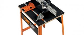
A lift for a router, which can be purchased in a serial version or made by hand, is a device that allows you to improve both the quality and accuracy of processing performed with hand-held power tools. The results of the latter strongly depend on how accurately and confidently the user manipulates such a device. In order to minimize the influence of the human factor on the results of processing performed with a manual milling cutter, special devices were developed.
Homemade elevator for a manual router, made of plywood and timber
One of them is a mechanized lifting device for milling power tools, which, in full accordance with its functionality, is called an elevator. As mentioned above, such a device can be purchased in a serial version, but it will not be cheap, so many home craftsmen successfully make it with their own hands.
milling table and lift for the router
To get a professional result you need a router table and a lift, router, bit and they don't have to cost a fortune or weigh a ton. My version of the milling table is 25 mm thick plywood, which does not require a cabinet or cabinets below and is attached to the workbench with clamps. The project has an adjustable lift and a stop with a dust collector.
How to make a router table and a router lift
Milling table and elevator, these are the first works on the milling table and they consist of preparing a place for the router and two metal rods for the elevator.
Notice in the photos that instead of mounting the router on removable plates, I use two metal guide rods that come standard with the tool. diameter of the rods. Having installed the router in the grooves on the table, secure it to the table using mounting blocks: bolt, washers and nuts
If your router does not have guide rods, then you will need to make changes to the attachment of the router to the base
diameter of the rods. Having installed the router in the grooves on the table, secure it to the table using mounting blocks: bolt, washers and nuts. If your router does not have guide rods, then you will need to make changes to how the router is attached to the base.
Assembling the router lift
The router lift consists of an open frame mounted on one of the mounting blocks. A nut is installed on the frame through which the threaded rod rotates using a round disk (Fig. 5,6). The manufacture of the elevator begins with the manufacture of the frame and (positions 3, 4, 5, 6 and 10) (Fig. 4). In order to prevent rotation of the elevator clamping bar (Fig.7)
around the router (position 10) (Fig. 4), four screws are screwed into the upper part of the router and they are aligned with the holes in the elevator clamping bar.
Creating a stop
Making the stop is not difficult. Prepare the vertical and horizontal bases (positions 11 and 12) (Fig. 4). Using a drill, jigsaw or router, form slots in the bases (Fig. 9). Make four triangular strips (item 13) (Fig. 4) to stiffen the stop.
You are ready to assemble the stop, connect the prepared parts together (Fig. 11). The ends of the auxiliary pads (item 14) (Fig. 4) for the stop, cut at an angle of 45°. Drill through holes for bolts in each trim.
note
Install the pads on the vertical support base and secure with bolts, washers and nuts (item 17) (Fig. 4). And lastly, the dust collector (position 15) (Fig. 4) is needed or not - it’s up to you to decide. Cut it to size, bevel the ends for a tighter fit.
Cut a hole in the dust collector bar that matches the diameter of the hose nozzle. Connect the dust collector bar and the stop using the curtain (position 16) (Fig. 4).
At the final stage
Many people write that for precision machining, each cutter must use a hole corresponding to the diameter of the cutter. A large diameter cutter is used, which means it requires a large hole in the base of the table.
If desired, make insert rings of different diameters, although these rings are optional and you can work with one large hole drilled in the base of the table (Fig. 4). Basically, in a hole with a diameter of 32 mm. will accommodate cutters of different diameters.
I note that in the process of processing products without insert rings, no large flaws were noticed that could not be eliminated with sandpaper. At the final stage, carefully sand the parts and apply several layers of durable coating.
Manufacturing process
We make a blank from plywood or chipboard to the size of the opening formed when the expansion table of the circular saw is fully extended. And according to the dimensions of the router sole, previously outlined with a pencil, we cut out a through hole. This will allow you to bring the sole of the router into the plane of the table, that is, it will allow you to use the reach of the cutter to the maximum.
We use metal rods with a diameter of 8 mm as holders. In this case, these are construction brackets with sawed off sides.
Now we mill grooves in the tabletop of such a depth that the sole of the router, lowered with holders into its niche, comes out in the same plane as the tabletop. We also mill places for wooden clamps.
We make wooden clamps ourselves, in which we drill through holes for mounting screws. On their back side, using a round file, we select semicircular grooves into which the metal holders will rest.
We drill holes in the table corresponding to the holes in the wooden clamps and fix the fastening screws.
We place the milling cutter with metal holders, which are inserted into the standard holes of the tool, into the table and fix it with wooden clamps, adjusting the precise exit into the same plane of the router sole and the table using wing nuts.
We reinforce the table with longitudinal stiffening ribs, securing them with glue and screws. Using a circular saw, we select quarters along the edges that allow the standard circular saw rip fence to move freely over the table.
The milling table itself is ready, now we need to make the elevator mechanism. From plywood 20 mm thick (in this case we glued together blanks from 10 mm plywood) we make a stationary stand. A plywood pusher is attached to it on an axis made of an M8 bolt and nut, resting with a semicircular protrusion on the router body. We make the pusher at both ends in the shape of a fork. Using metal cap plates, the pusher is connected to a movable block that slides along the threads of a long M8 bolt as it rotates.
We make the movable block from a wooden block and an M8 driven furniture nut.
On top of the table we make a blind hole with a diameter slightly larger than the diameter of the support bearing. We put the bearing on the bolt and place it in the hole. The bolt head will serve to operate the elevator mechanism.
On the reverse side, we fix the bolt with a self-locking nut, but do not tighten it completely, leaving the bolt free to rotate.
Our milling table with a simple and convenient lift is ready.
We fix the router in the made table, install everything in the extension of the circular saw. By rotating the bolt head, we smoothly raise the cutter to the desired height.
The milling cutter is ready to go.
How to choose a practical option
Technology for making cabinet furniture with your own hands
There are different ways to make a homemade milling table, but the design principles of most models are the same.
First, choose one of 3 types of milling installation, which determines the dimensions and location of this equipment in the carpentry workshop:
- Mounted. A separate aggregate unit, which is attached to the sawing machine on the side using clamps. Allows you to use the working surface of other equipment, can be easily removed, and put aside with your own hands when not needed.
- Portable. A desktop modification that is sought to be made with the minimum required dimensions of the bed and milling table. An efficient machine to use when frequently moving around construction sites.
- Stationary. The main type of table for established production, provided there is sufficient space in the room. This is no longer just a milling cutter, but an equipped workplace.
DIY materials
The working plane of the table ensures smooth sliding of the workpiece in one plane. Laminated chipboard and MDF sheets cope well with this task. To prevent the tabletop from bending under the weight of the router, take a slab with a cross section of 2.6/3.6 cm. For the side parts, a sheet of chipboard with a thickness of 1.6 cm or more is sufficient.
The mounting plate on which a massive router is attached, by definition, has high strength and rigidity. Sheet materials suitable for it are metal, textolite, and hardwood plywood. The thickness of the plate does not exceed 0.8 cm.
The load-bearing support of the table is made with your own hands from a metal profile or sheet chipboard. Sometimes these are just legs with elements of rigidity, in other cases the table includes front-mounted drawers for tools, small equipment, and utility devices.
The main part - the milling cutter - is purchased from industrial production.
Additional devices
The creative use of additional equipment in the design of a homemade milling table can significantly expand its functionality. You can achieve smooth adjustment of the height of the cutting part above the plate if you make a lift for the working tool with your own hands. For this purpose, the vertical axis of the assembly rests on a screw with a fine rectangular thread passing through a fixed nut. Rotating the flywheel on the rod regulates the feed of the cutter. The mechanism is equipped with side stops to prevent bending and a lock nut to hold it in a given position during vibration. If possible, they install more complex lifts - a car jack, a tailstock from a lathe.
Another addition is a steel ruler along the longitudinal axis of the guides of the workpiece. Practical, convenient, allows you to control the sample size, frees your hands for other operations.
Tool
To make all the details of the milling table with your own hands you will need:
- hacksaw, electric jigsaw;
- emery, grinding machine;
- electric planer;
- drill;
- chisel;
- screwdriver, screwdriver.
The use of electro-mechanical tools speeds up work on the manufacture of table tops, guides, oblique stops, but, if necessary, operations can be performed with your own hands and hand tools.
DIY milling table: drawings and diagrams
When milling any parts using a manual milling machine (we don’t remember industrial machines, they have completely different dimensions and capabilities), it is necessary to move the device along the surface of the stationary part.
If the router has guides for the task of moving, the task becomes a little easier, but their length does not usually allow working with any large parts. Therefore, there is a need for a special milling table.
What is a milling table?
This is a fairly large plane, made of durable material that can withstand loads well. The horizontality of the surface and the absence of unevenness are important - otherwise the work will be very difficult. Typically, the countertop is made of wood or its derivatives.
This is due to the fact that wood (plywood, chipboard and similar materials), produced in the form of a slab, already has a flat and smooth surface and dampens vibrations well during operation. A cutout (hatch) is made in the tabletop, and a manual router is attached to the bottom.
Standard models provide for fastening to a horizontal plane, and which side to do this on – top or bottom – is left to the user’s discretion.
In addition to the tabletop, supports are needed - strong, stable, capable of withstanding significant loads. Suitable for them are massive timber (section from 40x40 mm), flat panels, metal racks or a welded metal frame (assembled on corners and plates).
A metal plate placed on the tabletop at the cutout location
It protects wood from excessive loads and mechanical damage, and simplifies work with cutters. Another important advantage is the reduction in the thickness of the table, that is, providing a larger working stroke of the cutter compared to a thick tabletop.
When using a plate with a thickness of 2...3 mm, you can use almost the entire stroke of the cutter (35...70 mm, depending on the model), and for a tabletop with a thickness of 20 mm, all these millimeters are “subtracted” from the possible processing depth.
The plate is attached to the tabletop with screws (self-tapping screws) and must be quickly removed if necessary, so it is better to reinforce the mounting sockets with nuts or other elements with an internal thread of a suitable diameter driven into the wood.
In this case, the router itself is attached from below to the plate, and not to the tabletop, and can rise with it - this is convenient if you need, for example, to replace the router with an electric jigsaw or drill for drilling numerous holes in a long part.
The plate for a router for a table with your own hands must be made of high-quality, preferably non-rusting steel, rigid and durable, at least 2 mm thick (depending on the weight of the router and the properties of the steel).
The hole for the cutter must be processed along the edges, since the cutters will have to be changed quite often and it would be stupid to remove the device for this each time. I feel sorry for my fingers; they don’t need wounds from metal burrs.
Guides
Designed for uniform, smooth displacement of the workpiece along a given direction. The simplest guides are a flat beam screwed/nailed/glued to the tabletop at the required distance from the cutter. A more “advanced” option is guides with the ability to shift and/or rotate.
The easiest way to do this is to fasten the guide to the table with clamps, but this option does not guarantee a strong fastening - under the influence of vibration, the threads on the clamps “relax” and the guide begins to move out of the given position.
Therefore, it is better to provide a number of fastenings for the guides - with the ability to move the guide relative to the cutter axis, with the ability to rotate by a given degree.
By gluing (cutting) markings in the form of a regular measuring tape along the side edges of the tabletop and providing latches at the ends of the longitudinal guide for tight fastening, you can quickly change the distance from the working tool to the extreme plane of the workpiece.
You can also make a parallel stop for a milling machine with your own hands using screw fastenings, but then you can only move it with a certain pitch corresponding to the pitch of the threaded holes for fastening in the tabletop.
Another convenient option is to fasten aluminum (steel) guides along the end sides of the tabletop and equip the parallel stop with sidewalls with screw fastenings for these guides. Then smooth movement is possible.
If you make a horizontal insert from an aluminum (steel) profile with vertical stops moving along it in a displaceable guide, it will be easier to secure the workpiece.
Lift for router
DIY fiberglass bumper - manufacturing methods
Every craftsman who works with wood knows how inconvenient it is and how many unnecessary actions have to be performed to set the desired cutter height when working with a hand router, or to replace one cutter with another. To do this, you even have to remove the router from the table.
In order to significantly facilitate this task, a special device called a milling elevator was invented long ago, which is, in fact, the “third hand of the master” that helps regulate this process.
Currently, there are a large number of different models of milling elevators on sale. The best elevators are made in the USA and are quite expensive.
Not long ago, in one of the woodworking magazines, the design of a homemade elevator designed for a hand router was shown. This design will allow you to quite accurately adjust the height of the cutter, and making it yourself will not be difficult for a good craftsman. In addition, there is a detailed photo with a detailed description of the entire process of manufacturing such a model.
How to make a lift for a router in a workshop
When working on a milling table, it is very convenient to adjust the reach of the cutter “without leaving the cash register,” as they say. For this purpose, you can use a lift (elevator) for the router, which you can make yourself.
In this case, to make the milling table and the lift itself, the author uses laminated plywood, wooden blocks, a couple of steel cables, and some other materials.
The author makes a milling table from wooden blocks and a sheet of plywood. You need to cut a rectangular hole in the center and also make a lid with a round hole.
Main stages of work
From pieces of ordinary plywood, cut to size and furniture guides, the author assembles the main part of the lift for the router. You will also need a piece of threaded rod (or a screw of the appropriate diameter).
Next, you will need to cut another rectangular blank from laminated plywood with a hole for the back of the router. Then we take two cables and we can begin assembling the lifting mechanism.
At the last stage, the entire structure and a manual router are installed under the table. The result is a simple elevator that will help make work more comfortable.
For details on how to make a lift for a router with your own hands in a home workshop or garage, watch this video.
Rate this post
Source: https://sdelairukami.ru/kak-sdelat-podemnik-dlya-frezera-v-masterskoj/
Homemade table
Car strobe light is a simple circuit for DIY assembly. powerful strobe with your own hands, how to make a strobe with your own hands using simple spare parts
The most primitive drawing of a homemade table for a router is an MDF table top, in which a hole is made for the router to pass through and a guide ruler is attached - an evenly planed board. This tabletop can be placed between two workbenches or installed on its own legs. Its advantages are the simplest and quickly manufactured design. Such a device is unlikely to allow you to carry out serious woodworking. Let's consider more functional options, including a rotary one.
Small router table
neat and small table
A tabletop model for a hand router, which you can make yourself in a few evenings. The design is light and mobile, fits on a shelf, takes up little space, and its drawings are simple.
- The working surface and side racks are made of thick laminated plywood No. 15. The size of the table top is 40 x 60 cm, the height without the corner stop is 35 cm, the height of the stop is 10 cm. Three grooves are selected in the surface of the work table for installing rails. Various auxiliary devices are installed here and moved along the tabletop.
- To make the structure stable, the legs are made of chipboard or MDF No. 22. The legs are placed with a slight indentation, leaving a little space for attaching templates and clamps using clamps.
- To cover the mechanism, a front panel made of plywood or chipboard is installed below.
- The side stop has grooves along which it moves. Locked in the right place using bolts and wing nuts. The emphasis can be dismantled and any convenient device can be installed in the free space.
- A pipe is connected to the stop to remove chips that are released in abundance during operation. The chip drains of the router and the table are connected through plastic corrugations from the sewer siphons by a splitter for the water supply. A hose from a household vacuum cleaner is attached to a clamp. The result is a very effective system for removing chips; they practically do not scatter throughout the room.
- Since the machine is designed for a manual milling machine, a special on/off switch is not required.
- The stop consists of two parts, which are moved closer or further depending on the diameter of the working body. A wing nut is provided to secure the sash. The good thing about the proposed model is that the tool can be easily removed from the frame to replace the cutters.
- The mounting platform for the router is made of textolite or plexiglass. The plastic platform from the router kit is first dismantled. The recesses for the mounting area are selected with a router, and the hole is cut with a jigsaw. When the hole is ready, the plexiglass is adjusted to its size and shape. It should fit tightly and without protrusions into the window.
You can make several mounting platforms of the same size with holes for different cutter diameters.
This option is convenient for small hand tools. If a stationary table is being made for a large router, insert rings for different cutter diameters are attached to one mounting platform.
To ensure that the workpiece moves smoothly, motion stoppers are installed on the side stop. Clamps are also attached to the side stop, which hold the part near the cutter during operation. Additional convenience is provided by the slide, along which the workpiece moves at a right angle. And to make the work safe, pushers are manufactured.
The table is ready for use; its drawback is the lack of adjustment of the processing depth. This is done manually by pressing on the tool. It is impossible to “get” to the desired depth the first time. Therefore, we recommend equipping the table with a lift.
You need to make a hole in the frame into which an adjusting bolt with a wing nut is inserted. The depth of milling is smoothly changed by twisting the lamb.
Some craftsmen adapt old car jacks for a lift for a powerful router. The device is attached under the router; a hole is made in the side wall to bring the jack handle out. The jack handle can be bent at the desired angle; when rotated, the router smoothly moves up and down in 2 mm increments.
Another model of a homemade milling table for a router in the video:
Purpose and principle of operation of the lift
Even if the master is physically resilient, when working with a hand router, which weighs about 5 kg, his hands get very tired during the work. The lift installed on the tool allows you to increase accuracy, which simply cannot be achieved in manual work. The lift not only lifts the tool to the desired height, but also holds it there for the required time.
The movement of the router with the help of an elevator is carried out using a lever, crank or other lifting mechanism that is suitable for the design. This provides:
- Quick and accurate setting of the dimensions of grooves and other carved elements on the surface of wooden workpieces.
- Possibility to quickly replace tools if necessary.
The principle on which the mechanism works:
- A support plate for the tool is installed on the workbench.
- There are 2 racks on it, which are located parallel to each other.
- Actually, the tool itself is installed on a movable carriage. It moves freely up and down the racks.
- The carriage and elevator move to the required distance due to a special pushing device.
The principle of operation is simple, and therefore making such a unit yourself will not be difficult either. You can also purchase a serial version, but in this case you need to choose the right mechanism.
Table design
The simplest design of a milling table involves the presence of three main elements - a working surface or tabletop, a machine base or bed, and additional equipment - a limit bar, adjustment devices, and safety devices.
Among the device layout diagrams that can be found on the Internet, all designs can be divided into three types:
- Multifunctional free-standing devices for working and storing tools.
- Tabletop small-sized tables for milling, which are installed on a workbench or desktop.
- Tables are attachments that are attached to brackets or special seats to a workbench or desktop.
And if the former require a certain skill and skill for design and assembly, then desktop structures and milling attachments can be made independently from drawing development to practical implementation.
The basis of the table is the bed - a rigid structure on which the working surface of the milling table - the tabletop - is placed, there is a mount for installing the tool and equipment for fixing and adjusting it.
The entire structure is made of wood and lumber, held together with glue and screws to assemble the furniture. Structurally, a simple table for a router should be of a rigid and stable structure to dampen vibration and at the same time be lightweight so that it can be easily moved from place to place.
Required materials and tools
When preparing for the main work, you need to take care of the tools that will be needed to install the structure. They need to be prepared in advance so that all the equipment is at hand. If any element is missing, everything can be purchased at any hardware and hardware store.
To build an elevator for a router you will need:
- Metal sheet;
- bolts and screws of different sizes;
- aluminum profile;
- jack;
- drill;
- milling cutter;
- epoxy adhesive;
- roulette;
- square and pencil;
- Chipboard and plywood sheets;
- threaded rod.
It is necessary to remove the handles from the router in advance for the convenience of further work. After preparing all the tools, you can begin the main work.
Manufacturing materials
The correct choice of table materials determines its service life and the quality of milling of parts. What materials are recommended to be used for these purposes?
Table. Types of tables by material of manufacture
| Type of table for a router | Brief description of physical and operational characteristics |
| Plywood | Most often used. In terms of cost and performance indicators, the most suitable option, you just need to buy special plywood, its veneer is glued with especially strong two-component polymer adhesives. This type of plywood is not recommended for use during furniture manufacturing; the amount of phenols and formaldehydes released into the air exceeds permissible standards. But in the workshop the material can be used without fear. But in terms of strength, this type of plywood confidently occupies a leading position, and this is the most important characteristic. |
| Metal | A metal table has been in use for many decades, but to manufacture it you must have practical experience in welding work. Another problem is that some parts need to be sharpened; almost no one has a lathe at home, so you have to turn to specialized companies. |
| Combined | Highly recommended for use. Some of the most loaded elements are made of metal, the rest can be wooden. By the way, the table does not have to be made from scratch - after a little reconstruction, ordinary prefabricated/collapsible small kitchen tables fit perfectly. These were once in every apartment and today are still used in utility rooms. |
You can also use glued furniture panels made from natural lamellas; they do not change their size with fluctuations in relative humidity, but such a table for a router will be very expensive. It is strictly forbidden to use natural boards due to constant warping in one direction or another, which has an extremely negative impact on the quality of milling.
A tabletop made of boards is not suitable for making a milling machine.
We will give step-by-step instructions for making two simple, but very functional, tables for a router. The dimensions are given only general, specific ones depend on the type of hand router, and there are a huge number of them in sale
Each model differs in several parameters that must be taken into account during work.
Scheme for assembling a table for a manual router. 1 — side strip for fastening with clamps on trestles; 2 - drawer; 3 — countersunk guide holes; 4 — front wall of the stop; 5 - self-tapping screw with countersunk head 4.5x42 mm; 6 - scarf; 7 - support base
Peculiarities
When equipping an industrial or home workshop, a master can purchase a lift for a mass-produced router or make the required equipment himself. The quality of material processing with hand tools usually depends on the professionalism of the user. To reduce the risk of errors due to inattention and the influence of the human factor to a minimum, it is recommended to automate the process as much as possible using special devices.
One of these tools is a lift designed to be installed in a table, which is responsible for changing the position of the hand tool, moving it smoothly. Such devices can be bought in specialized stores, where a large assortment of models from different manufacturers is presented. However, the cost of the devices can be quite high. Therefore, most home craftsmen prefer to make the lifting mechanism themselves.
Milling table design
If you wish, you can make a homemade milling table from a regular workbench, but it is better to make a special design. This is explained by the fact that a machine with a milling cutter creates strong vibration during operation, so the bed used to fix the milling cutter must be highly stable and reliable. It should also be taken into account that the milling device itself is attached to the bottom of the tabletop for the milling table, so there must be enough free space under it.
When attaching the device to the top of a homemade table for a manual router, a mounting plate is used, which must have high strength and rigidity, or special clamps for a milling machine. Such a plate can be made of metal sheet, textolite or durable plywood. The bases of most router models already have threaded holes; these are what are needed to connect such a device to the tabletop and mounting plate. If there are no such holes, you can drill them yourself and cut threads into them, or use special clamps for a milling machine.
Milling cutters for various types of processing on a milling table
The clamps for the milling machine or the mounting plate must be located at the same level as the tabletop; for this purpose, the latter is sampled with the appropriate dimensions. It is necessary to drill several holes in the plate, some of which are necessary to connect it to the tabletop using self-tapping screws, and others so that such a plate can be fixed to the base of the router. The screws and self-tapping screws that you will use must have a countersunk head.
To make turning on your device more convenient, you can place a regular button on the tabletop, as well as a mushroom button, which will make your device safer in operation. To increase the convenience of your home machine, you can attach a long metal ruler to the surface of a milling table made for a manual router with your own hands.
Before you start constructing a milling coordinate table with your own hands, you need to determine the place where it will be located, and also decide what type of milling equipment you want to make. So, you can make an aggregate router with your own hands (the table will be located on the side of the sawing equipment, serving as its extension), a compact desktop machine, or free-standing stationary equipment.
You can opt for compact benchtop equipment for working with wood and other materials if you access it irregularly or often use it outside your workshop. This installation, which is distinguished by its small size, takes up very little space, and if desired, it can be hung on the wall.
If the size of your workshop allows, then it is better to adapt the base of a stationary milling machine for the milling machine, which is much more convenient to work on than on desktop equipment. To make such a device more mobile, it can be placed on wheels, with which you can easily change its location.
A simple milling table or table for a drilling machine can be made very quickly. To make such a structure, which can easily be placed on a regular desktop, you will need a sheet of chipboard on which the guide elements are fixed. As such a guide, which can be used as a parallel stop for a milling table, an ordinary board of small thickness, which is attached to the tabletop using bolted joints, is suitable. If necessary, you can attach a second such board in parallel, which will serve as a limiting stop.
To insert a router into a table, you will need to make a hole in a sheet of chipboard to accommodate it, and it will be fixed to the tabletop using two clamps. After this, the manufacture of the milling table can be considered complete. To make the use of this design more convenient, you can place simple clamps for a milling machine on the tabletop.
Why is such a device needed?
A lift for a router, which ensures precise movement of a hand-held power tool mounted on it in a vertical plane, is necessary in many situations. Situations in which the quality and precision of processing of wood products are of no small importance include decorative finishing of furniture panels, making technological grooves and lugs on elements of furniture structures. The quality of processing in such cases will not depend on the experience of the master performing it and the firmness of his hands, but only on the accuracy of the device settings and the degree of its stability.
Even a person with good physical fitness gets tired when working with a hand router, the weight of which can be 5 kg or even more. This directly affects the accuracy and quality of work. In addition, the precision of processing that a manual milling machine mounted on an elevator can provide cannot be achieved when manipulating a power tool manually.
For most routers, standard adjustment when installing the tool in the table becomes simply inconvenient
The need to invent such a useful device as a lift for a router was driven by the fact that the variety of types of decorative finishing of wood products has expanded significantly, the technological methods for processing this material have become more complex, and the requirements for the accuracy of its implementation have also increased. All of the above factors require that manual milling electrical equipment combine high mobility of its working body, as well as the accuracy of the movements it makes. It is these requirements that are fully met by a lift for a router, with the help of which the power tool used is quickly raised and lowered to the required height above the workbench, and also held at a given level for the required amount of time.
The convenience of using a milling elevator also lies in the fact that it is not necessary to install a power tool on such a device each time. This helps to both simplify the production process and increase its productivity.
How to make it yourself
To make an elevator with your own hands, you need a certain set of tools, as well as instructions and drawings. There are several options for what to assemble such a structure from. The most popular is the jack.
What will it take to do
To manufacture a lifting mechanism on your own, you will need a whole list of tools, technical devices and various materials. You should have:
- directly to the router, the handles are first removed from it;
- electric drill;
- an ordinary car jack;
- textolite or metal sheet;
- wooden bars (square cross-section);
- aluminum profile;
- plywood and chipboard;
- metal guides;
- threaded rod;
- wrenches, pliers and screwdrivers of different sizes;
- drills of different diameters;
- epoxy adhesive;
- square, ruler, tape measure.
You may also need a grinder and a welding machine. It all depends on the specific assembly scheme, since there are several options.
Instructions and drawings
Home craftsmen most often use a standard machine jack to make a lifting mechanism. But there are also designs, the components of which are: a support disk with a threaded rod and a flywheel disk, there are options with a chain drive and microlifts. Each system has separate manufacturing instructions.
From the jack
The operating principle of this mechanism is based on raising and lowering the working head of the milling cutter using the control of a standard jack from the car.
Manufacturing algorithm:
- A box should be made from chipboard or 15 mm plywood, which must be attached to the bottom of the desktop. The box is simultaneously a protective casing for all devices and a supporting device for the structure.
- Inside the box there should be room for a jack and a hand router, which is attached to the moving part of the jack.
- Screw the jack from the bottom of the support casing.
- Attach a hand router to the inner surface of the workbench tabletop.
- The support plate in such a device will be a metal or textolite sheet.
If desired, you can add an electric drive to the design, but this will be more expensive equipment.
With threaded rod
This design requires a threaded rod, a small handwheel and a support disk. Manufacturing instructions:
- you need to get a board, the thickness of which is 1.8 cm and cut out a circle - this is a support for a hand router;
- in the center of the circle, cut a hole with a diameter of 1 cm; a threaded rod with a length of at least 5 cm is placed here;
- connect the stud to the support platform using two nuts and washers;
- connect the lower part of the stud to the flywheel;
- A flange nut is built into the bottom of the hole through which the lower part of the stud will be passed. She will be directly responsible for the functioning of the entire mechanism.
Also in this design you can use a mechanism that will provide the power tool with sideways movement.
With chain drive
This manufacturing option takes longer. The design is a frame where the lower milling plate is connected to the upper one using pins, which are the main working tool along which the movable insert moves.
The movable insert is a two-layer plate, between the layers of which nuts with stars mounted on them are inserted. The drive sprocket is mounted through a bushing onto the shaft
It is important that the drive and driven sprockets have a tooth ratio of 1:2. For the design you can use a standard bicycle chain
It is imperative to ensure chain tension for the structure to function properly. To do this, it is necessary to install a metal crescent into the structure, which will have tension at one of the corners and at the same time rotate freely. An eccentric is mounted nearby, when turned, the crescent will be pressed weaker or stronger, which ensures chain tension.
Microlift
A microlift can be made quite simply using a running nut and a cable. First you need to secure the platform for the lower elevator roller. Then you should adjust the height of the roller and the shape of the platform. Before installation, the stud must be adjusted to size using a lathe. The result will be a pin-shaft.
You need to make a loop on the cable. Then the flywheel is installed, and the loop is secured to the running nut in the guide. As a result, 10 rotations of the flywheel can result in 9.5 mm of cutter movement.
What is needed to make a milling elevator
In order to make your own milling lift, you must prepare the following set of consumables, tools and technical devices:
- directly the manual router itself, from which it is necessary to remove the handles;
- electric drill;
- standard car jack (if the lifting mechanism of the device is of the jack type);
- sheet of metal or textolite;
- wooden blocks of square section;
- aluminum profile;
- sheets of plywood and chipboard;
- guides made of metal;
- threaded rod;
- a set of screwdrivers of various types and sizes, wrenches and pliers;
- drills of various diameters;
- bolts, screws, nuts and washers of various sizes;
- epoxy adhesive;
- square, ruler, measuring tape.
In general, only the motor and stands can be used from the router, especially if the tool does not have high accuracy of movement along the telescopic guides
Buy or make it yourself?
There is a wide choice of offers on the power tool market. Industrial microlifts look good and work without failures, but their cost is the same as that of a new router. True, the device is quite well equipped. The kit includes rings for the copy sleeves, and a very high quality mounting plate.
Industrial microlift for a router with a set of copy rings
All that remains is to electrify the device - and you can get a CNC machine. There is only one drawback, but it outweighs all the advantages - the price itself. Therefore, for occasional home use this is an unaffordable luxury. So our Kulibins make whatever they can. However, there is a lot to learn from them.
Nuances of choice
If you are planning to purchase a milling lift for mass-produced hand tools, then you should approach its choice very responsibly. Not only ease of use, but also processing accuracy will depend on the quality of the equipment.
The main attention should be paid to the following technical characteristics of the lifting device:
- functional plate size;
- features of changing the engine position;
- lead screw characteristics;
- working parameters.
It is also worth considering that high-quality and reliable structures must have the following properties:
- smooth movement during operation, there should be no sudden jerks or jumps that could interfere with the processing process;
- ease of installation, which allows you to independently carry out maintenance of devices and repair them if the need arises;
- durability of the mechanism and its resistance to high-intensity loads.
A lift will really make your work easier and increase efficiency. The purchase of a factory-made lift is relevant and justified for equipment in a workshop or small industrial enterprise. Such equipment is designed for durable operation under high-intensity load conditions.
If you don’t find a model suitable for your requirements, or its cost seems too high, then you can make a screw milling elevator for woodworking yourself. Tips and instructions will help you with this.
This is interesting: Where to connect the ground wire and how to ensure the fixation of parts during welding
Electric lift for milling table. Part 1. — DIY Community on DRIVE2
Electric elevator for a milling table. With the appearance of a router and, subsequently, a milling table in my tool park, I began to think about the need to equip it with an elevator for a router and not just an elevator, but an elevator with an electric drive, which was implemented. This is what the finished result of my “creativity” looks like...
Before starting work, in order not to reinvent the wheel, I decided to look at what had already been “invented” before me. There are a lot of publications on the Internet about various elevators for milling tables.
On YouTube, on the page of Maxim Kozlov (if my memory serves me correctly, many people know him under the nickname “Papa Carlo”), I came across a description of the manufacture of a “Elevator for a router”, which immediately attracted me because the design proposed by Maxim easily makes it possible to make an electric drive and therefore its idea (in relation to the mechanism of the elevator itself) I decided to repeat... The process of manufacturing the elevator is described in great detail in Maxim’s videos (see
).Therefore, I will not repeat myself... I will dwell only on some of the features of my design... I began determining the dimensions of the future elevator by measuring the size of the cutter output (the distance between the upper and lower position of the sole) determined by the design of the hand router mechanism (see figure).
Taking as a basis the known dimensions of the table itself and the required maximum value of the cutter output (in my case 35 mm), I modeled on a computer (in a graphic editor) a diagram of the kinematics and movement and interaction of the elements of the elevator pantograph.
As a result of the simulation, the calculated value of the vertical movement of the elevator was 54 mm, with the horizontal movement of the moving part being 56.4 mm. Such calculated data provided a lifting height margin of 20 mm, with horizontal movement of the moving parts, not exceeding the dimensions of the milling table.
During modeling, I calculated the distances between the holes (pantograph elements) and the main dimensions of its elements.
Based on the calculated dimensions, in accordance with the diagram of kinematics and interaction of pantograph elements, I developed drawings.
For many years now, before making a product (craft), I have been trying to first develop a drawing, albeit not of very high quality in graphic design, but with specific real dimensions.
This approach allows you to get rid of waste of material and already at the drawing stage think through many of the nuances of the product design. Of course, I don’t deny that you don’t take a lot into account and have to do it on the spot, but, as a rule, it’s all about the little things.
As an electric drive, I used a used window lift from a car, which is an electric motor (12 volts) with a worm-type gearbox. I carefully measured the overall and mounting dimensions, which I also prepared in the form of a drawing.
In accordance with the drawings, I made pantograph elements from a birch block 40 mm thick, namely the left and right fixed supports, the movable lower and movable upper supports (elements). Using a template made of sheet metal, I drilled holes with a diameter of 8 mm for the axis of rotation of the pantograph bars.
In addition, in the lower movable and right fixed supports, I drilled a hole with a diameter of 8 mm for a threaded rod, which will act as a tightening or expanding screw.
In the left fixed support, using a Forster drill, I drilled a hole with a diameter of 20 mm to a depth of 20 mm, under the nuts for securing the axis against horizontal movement.
I made pantograph strips from plywood 8 mm thick. The holes were drilled using a template.
The use of a template, in addition to ensuring the accuracy and uniformity of the distance between the holes, can significantly speed up the manufacturing process (there is no need to mark each strip).
Then, temporarily fastening all the planks together, I processed them on a disc grinder. Since I used used plywood from equipment boxes for the work, partial delaminations and chips are visible, which did not affect the functioning of the elevator.
I pre-attached the pantograph elements and simulated the operation of the elevator (in manual mode for now).
Modeling has shown that the design easily (even with a margin of almost 1 cm in each direction) provides the expected minimum and maximum lifting heights.
In addition, with the help of preliminary assembly, I determined the actual overall dimensions of the elevator mechanism, both vertically and horizontally (in the maximum raised position and in the minimum height position).
I made the base of the elevator mechanism from 8 mm plywood; to ensure the movement of the lower movable support, I also made a bed (“track”) from strips of 8 mm plywood along which the lower movable support will move.
I started assembling the pantograph. I used an aluminum tube with a diameter of 8 mm as axes, securing them in strips according to the method outlined by Maxim Kozlov.
I glued an M8 mortise nut into the lower movable support, additionally securing it with self-tapping screws.
At the left end of the threaded rod, I made a support unit, which is a metal plate, 2 mm thick, with an 8 mm hole through which the rod passes.
From horizontal movement, the pin is secured on each side through a metal washer (with the addition of Litol lubricant) with a locked nut.
I deliberately avoided using bearings, believing that based on the planned rate of use of the milling table, the support unit would not fail. The plate of the support unit was fixed with self-tapping screws on the left fixed support.
Having installed the base of the elevator mechanism on horizontal supports on the milling table, I determined the mounting location for the elevator base so that the central longitudinal axis of the elevator coincides with the vertical axis of the router. After that, I marked and drilled a hole in the side wall of the table for a screw pin. A drive motor with a gearbox will be installed on the opposite side of the side wall of the table.
Continued in the second part www.drive2.ru/c/498486687270175101/.
Source: https://www.drive2.ru/c/498486412392267782/
Make a lift for the router yourself, or buy a ready-made one? Let's answer this question
When using a manual router installed in a stationary table, two questions arise:
- How to adjust the depth of immersion (extension) of a cutter.
- How to quickly change replacement tips.
Unscrewing the tool from the plate every time is too troublesome. In addition, a statically mounted router works in the workpiece only at a fixed depth.
This problem is solved by installing a height-adjustable suspension on the router. And once you were able to make a full-fledged milling table, installing an elevator of your own design is not difficult at all. In addition, a self-made device is developed taking into account all the requirements of the master, even those that are not provided for by the factory device.
Why do you need a lift on the milling table, and is it possible to do without it?
This useful device is called the third hand of the master. Those who have tried a milling cutter with a microlift are finding new applications for it:
- Maintaining a power tool is not difficult, as is quickly changing cutters.
- You can change the cutter reach height in a matter of seconds, and most importantly – safely.
- You can change the immersion depth “dynamically”, simultaneously with the movement of the workpiece on the table. This expands creativity.
- Due to the fact that you no longer regularly dismantle the tool for maintenance, the plate and its fasteners are subject to less wear.
Buy or make it yourself?
There is a wide choice of offers on the power tool market. Industrial microlifts look good and work without failures, but their cost is the same as that of a new router. True, the device is quite well equipped. The kit includes rings for the copy sleeves, and a very high quality mounting plate.
Industrial microlift for a router with a set of copy rings
All that remains is to electrify the device - and you can get a CNC machine. There is only one drawback, but it outweighs all the advantages - the price itself. Therefore, for occasional home use this is an unaffordable luxury. So our Kulibins make whatever they can. However, there is a lot to learn from them.
There are quite primitive lever-type designs
Homemade elevator design with a lever mechanism
This technique even allows the use of a “foot” drive.
It is not suitable for precise reach settings, however, with the help of such a mechanism, you can raise the router to the working position with one movement, and just as easily lower it to change the attachment or service.
This elevator has a fairly long stroke; it does not allow for adjustable milling. Materials for manufacturing are literally lying underfoot, the cost tends to zero.
Popular: Working with a manual wood router: basic principles
Using a Screw Adjuster
Another example of a homemade elevator for a router
The design is more advanced and allows relatively precise adjustment of the reach. However, using such a microlift is inconvenient; to rotate the handle, you need to crawl under the table, and then make a control measurement of the height of the cutter. But the reliability is high, and production does not require expensive materials. Such an elevator can be made “by eye” without using drawings.
The following flywheel design not only makes it possible to precisely adjust the reach in small increments within 50 mm, but is also quite convenient.
Lifting design with flywheel
It will take more time to make, but the result is worth it. The flywheel allows you to adjust the height of the cutter, while simultaneously visually monitoring it above the working surface. In principle, it is already possible to dynamically change the cutter offset.
The main advantage is the still low cost of components for manufacturing, with increased functionality. Instead of a flywheel, you can install a gear and a motor with a gearbox. But this will require additional costs.
Option with car jack
Quite expensive, since at a minimum you need to purchase a jack. Diamond-shaped designs are ideal.
Using a screw jack as a lift for a router is also possible
This microlift lift is reliable, and thanks to the handle located parallel to the tabletop, it is convenient and quite accurate. Positioning the mount is quite simple. It is enough to install a strong shelf parallel to the tabletop. An electric drive option is available.
Then, in general, you can install a foot pedal and free both hands. And if you add a programmer to all this, you have a homemade CNC router. However, this goes beyond the concept of an economy class device.
Option from an advanced master
Since the possibilities of a craftsman are limitless, you can come across completely unexpected designs. This microlift is made using the very same router for which it is intended.
Original elevator design made by hand
The design involves not only precise adjustment of the reach, but also changing the angle of inclination of the router axis. With this potential, you can significantly expand your woodworking tasks. The drive of the worm gear of the stud – the height regulator – was originally designed.
Gears (gears) are made using the dovetail tenon method. This allows you to move the gears outside the mechanism, eliminates the need for lubrication, and makes adjustment soft. The material used is moisture-resistant plywood 20-25 mm thick. The microlift is made so well that I would like to suggest that the author organize industrial production.
Of course, such a design requires a preliminary drawing.