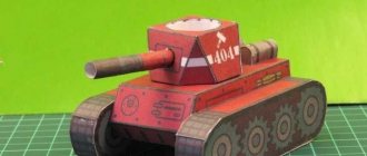
A transformer that increases voltage and frequency many times is called a Tesla transformer. Energy-saving and fluorescent lamps, picture tubes of old TVs, charging batteries from a distance and much more were created thanks to the operating principle of this device. Let’s not exclude its use for entertainment purposes, because the “Tesla transformer” is capable of creating beautiful purple discharges - streamers reminiscent of lightning (Fig. 1). During operation, an electromagnetic field is formed that can affect electronic devices and even the human body, and during discharges in the air a chemical process occurs with the release of ozone. To make a Tesla transformer with your own hands, you do not need to have extensive knowledge in the field of electronics, just follow this article.
Principle of operation
The Tesla transformer consists of two windings - primary (Lp) and secondary (Ls) (they are more often called “primary” and “secondary”).
An alternating voltage is applied to the primary winding and it creates a magnetic field. With the help of this field, energy is transferred from the primary winding to the secondary. In this respect, the Tesla transformer is very similar to the most common “iron” transformer. The secondary winding, together with its own parasitic (Cs) capacitance, forms an oscillatory circuit that accumulates the energy transferred to it. Part of the time, all the energy in the oscillating circuit is stored in the form of voltage. Thus, the more energy we pump into the circuit, the more voltage we get.
A simple diagram of how a Tesla coil works.
Tesla has three main characteristics - the resonant frequency of the secondary circuit, the coupling coefficient of the primary and secondary windings, and the quality factor of the secondary circuit.
The reader should know what the resonant frequency of an oscillatory circuit is. I will dwell in more detail on the coupling coefficient and quality factor.
The coupling coefficient determines how quickly energy is transferred from the primary winding to the secondary, and the quality factor determines how long the oscillating circuit can retain energy.
Seesaw analogy
In order to better understand how an oscillatory circuit accumulates energy, and where such a large voltage comes from in a Tesla, let’s imagine a swing that a huge man is swinging. The swing is an oscillatory circuit, the man is the primary winding. The speed of the swing is the current in the secondary winding, and the height of the rise is our long-awaited voltage.
The man pushes the swing, and thus transfers energy into it. And so, after a few pushes, the swing swayed and flew as high as possible - it had accumulated a lot of energy. The same thing happens with a Tesla, only when there is too much energy, an air breakdown occurs, and we see our beautiful streamers.
Naturally, the swing should not be swayed anyhow, but in exact accordance with its own vibrations. The number of times the swing oscillates per second is called the “resonant frequency.”
The section of the swing's flight path during which the man pushes it determines the coupling coefficient. If a man constantly holds the swing with his hefty hand, he will swing it very quickly, but the swing can only deviate by the length of the man’s arm. In this case, the coupling coefficient is said to be equal to one. Our swing with a high coupling coefficient is an analogue of a conventional transformer.
Now consider a situation where a man pushes the swing just a little. In this case, the coupling coefficient is small, and the swing deviates much further - the man now cannot hold it. The swing will take longer to swing, but even a very frail man can handle it, pushing it a little each period of oscillation. Such a swing is an analogue of the Tesla transformer. The higher the coupling coefficient, the faster energy is pumped into the secondary circuit, but at the same time the output Tesla voltage is lower.
Now let's look at the quality factor. Good quality is the opposite of friction in a seesaw. If the friction is very high (low quality factor), then the man will not be able to swing them with his weak pushes. Thus, the coupling coefficient and the circuit quality factor must be matched to achieve the maximum swing height (maximum streamer length).
Since the quality factor of the secondary winding in a Tesla transformer is not a constant value (it depends on the streamer), it is not very easy to reconcile these two values, and therefore they are simply selected empirically. A brief description of the operating principle of the transformer can be seen in the video.
Part one - body
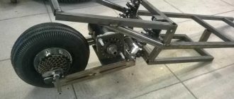
I’ll say right away that I already had the chassis from one of the old, never completed projects. The most common option is to take two Soviet round stools and break them, hehe. Next, if desired, fasten the seats of the stools with self-tapping screws and some kind of material. In the middle there is a board with a height of 350mm, a width in diameter, a thickness of 15-20mm and three or four boards around the circumference in order to give rigidity to the structure. For installation it is worth using corners, for example, and self-tapping screws.
You can take not stools, but kosher thick electrical textolite, which is used to install panels in electrical cabinets, but it can cost you a pretty penny, unless of course you buy it for a bottle from the electrician Vasya.
Fastenings for the primary winding can be made using a 22x75 wooden block, remembering the labor lessons at school, hehe.
(yes, line weights are for weaklings, who knows why it was converted like that, but it seems readable).
Coil device
The Tesla transformer, the diagram of which will be presented below, consists of two coils, a toroid, a protective ring and, of course, grounding.
Tabletop CT sketch
It is necessary to consider each element separately:
- The primary coil is located at the very bottom. Power is supplied to it. It must be grounded. Made from low resistance metal;
- secondary coil. For winding, enameled copper wire of approximately 800 turns is used. This way the coils will not unravel or get scratched;
- toroid. This element reduces the resonant frequency, accumulates energy and increases the working field.
- protective ring. It is an open loop of copper wire. Set if the length of the streamer is greater than the length of the secondary winding;
- grounding If you turn on an ungrounded coil, streamers (current discharges) will not shoot into the air, but will create a closed ring.
CT drawing
Coil calculation
Calculation of CT is usually carried out during the manufacture of an industrial-sized transformer. For home experiments, it is enough to use the above recommendations.
The calculation itself will tell you the optimal number of turns for the secondary coil depending on the turns of the first, the inductance of each coil, the capacitance of the circuits and, most importantly, the required operating frequency of the transformer and the capacitance of the capacitor.
CT calculation example
Main types of coils
Homemade tesla coil.
Tesla himself manufactured only one type of Transformer - a spark gap (SGTC).
Since then, the element base has greatly improved, and many different types of coils have appeared; by analogy, they continue to be called Tesla coils.
Coil types are usually named from English abbreviations. If the name must be said in Russian, English abbreviations are simply spoken in Russian letters without translation. We will consider the most common types of Tesla coils below.
SGTC (SGTC, Spark Gap Tesla Coil)
Tesla transformer on a spark gap. The very first and “classical” design (it was used by Tesla himself). It uses a spark gap as a key element. In low-power designs, the arrester is simply two pieces of wire located at some distance, while in high-power designs, complex rotating arresters are used. Transformers of this type are ideal if you only need a long streamer length.
VTTC (VTTC, Vacuum Tube Tesla Coil
Tesla transformer on a lamp. A powerful radio tube is used as a key element. Such transformers can operate in continuous mode and produce thick, “fat” streamers. This type is most often used for high-frequency adzes, which, due to the characteristic appearance of their streamers, are called “torch”.
SSTC (SSTC, Solid State Tesla Coil)
Tesla transformer, which uses semiconductors as a key element. Usually these are MOSFET or IGBT transistors. This type of transformers can operate in continuous mode. The appearance of the streamers created by this coil can be very different. This type of Tesla is the easiest to control (play music, for example).
Solid State Tesla Coil type.
Power supply circuit
For the initial start-up, a circuit is required that supplies a pulse of energy to the Tesla generator transformer. Next, the generator switches to self-oscillating mode and does not constantly need external power.
In developer slang, the power supply device is called a “kacher”. Those familiar with electronics know that the correct name for the device is a blocking oscillator (shock oscillator). Such a circuit solution generates a single powerful electrical impulse.
Many variants of blocking generators have been developed, which are divided into three groups:
- On vacuum tubes;
- On bipolar transistors;
- On field-effect transistors with an insulated gate.
A tube electromagnetic generator using powerful generator tubes operates with high output parameters, but its design is hampered by the availability of components. In addition, not two, but three winding transformers are required, so tube blocking oscillators are now rare.
Tube blocking generator
The most widely used devices are those based on bipolar transistors. Their circuitry is well developed, setup and adjustment are simple. We use domestically produced transistors of the 800 series (KT805, KT808, KT819), which have good technical parameters, are widespread and do not cause financial difficulties.
Blocking oscillator based on a bipolar transistor
The proliferation of powerful and reliable field-effect transistors has made it possible to design blocking oscillators with increased efficiency due to the fact that MOSFET or IGBT transistors have better parameters for voltage drop across transitions. In addition to increasing efficiency, the problem of cooling transistors becomes less problematic. Proven circuits use IRF740 or IRF840 transistors, which are also inexpensive and reliable.
Field effect transistor circuit
Before assembling the generator into a finished structure, double-check the workmanship of all components. Assemble the structure and supply power to it. The transition to self-oscillating mode is accompanied by the presence of voltage on the windings of the transformer (at the output of the secondary). If there is no voltage, then it is necessary to adjust the frequency of the blocking generator in resonance with the frequency of the transformer.
Important! When working with a Tesla generator, extreme caution must be exercised, since when starting, high voltage is induced in the primary winding, which can lead to an accident.
Main parts of the reel
Although there are several types of Tesla coils, they all have common features. Let's talk about the main details of the Tesla from top to bottom.
Main parts of a tesla transformer coil.
Toroid
Toroids are usually made from aluminum corrugation, although there are many other technologies available. Performs three functions:
- The first is reducing the resonant frequency - this is important for SSTC and DRSSTC, since power semiconductors do not work well at high frequencies.
- The second is the accumulation of energy before the formation of a streamer. The larger the toroid, the more energy is accumulated in it and, at the moment when the air breaks through, the toroid gives off this energy to the streamer, thus increasing it. To take advantage of this phenomenon in continuously pumped Teslas, a chopper is used.
- The third is the formation of an electrostatic field, which repels the streamer from the secondary winding of the tesla. In part, this function is performed by the secondary winding itself, but the toroid can help it well. It is precisely because of the electrostatic repulsion of the streamer that it does not take the shortest path to the secondary.
Pulse-pumped teslas - SGTC, DRSSTC and chopper teslas - will benefit most from the use of toroidoa. The typical outer diameter of a toroid is twice the diameter of the secondary.
Interesting material on the topic: how to assemble a step-up transformer yourself.
Secondary
The typical ratio of the length of the tesla winding to its winding diameter is 4:1 – 5:1. The diameter of the wire for winding a tesla is usually chosen so that 800-1200 turns are placed on the secondary. ATTENTION, I will repeat it again. Do not wind too many turns on the secondary with a thin wire. The coils on the secondary should be placed as close to each other as possible.
To protect against scratches and the turns coming apart, the secondary windings are usually coated with varnish. Most often, epoxy resin and polyurethane varnish are used for this. It is necessary to varnish in very thin layers. Usually, at least 3-5 thin layers of varnish are applied to the secondary.
They wind the secondary on air duct (white) or, worse, sewer (gray) PVC pipes. You can find these pipes at any hardware store.
Protective ring
It is designed to ensure that the streamer, once it gets into the primary winding, does not damage the electronics. This part is installed on the tesla if the length of the streamer is greater than the length of the secondary winding. It is an open turn of copper wire (most often, a little thicker than the one from which the primary is made). The protective ring is grounded to the common ground using a separate wire.
Primary winding
Typically made from copper pipe for air conditioners. It must have very little resistance in order for a large current to pass through it. The thickness of the tube is usually chosen by eye; in the vast majority of cases, the choice falls on a 6 mm tube. Also, larger cross-section wires are used as primary wires.
Relative to the secondary winding, it is set so as to provide the desired coupling coefficient. It often plays the role of a building element in those teslas where the primary circuit is resonant. The connection point to the primary is made movable and its movement changes the resonant frequency of the primary circuit.
There are Tesla transformers without a primary winding. They supply power directly to the “ground” end of the secondary. This feeding method is called “basefeed”.
Primary windings are usually made cylindrical, flat or conical. Typically, flat primary is used in SGTC, conical in SGTC and DRSSTC, and cylindrical in SSTC, DRSSTC and VTTC.
Grounding
A very important part of the Tesla. The question is often asked: where are streamers going? We answer this question - streamers hit the ground! And thus they close the current, shown in blue in the picture.
Thus, if the grounding is poor, the streamers will have nowhere to go and will have to hit the Tesla (short-circuit their current) instead of erupting into the air. I was asked: is it necessary to ground a Tesla? So, the answer is: grounding for a Tesla is mandatory.
Theoretically, for an adze, instead of grounding, you can use the so-called counterweight - artificial grounding in the form of a larger conductive object. There are very few practical designs with counterweights.
Attention! The manufacture of adzes with counterweights is much more dangerous than adzes with simple grounding, because the entire structure is under a high potential relative to the ground. And a relatively large capacity between the counterweight and surrounding objects can negatively affect them.
Tesla coil
Hamsters welcome you, friends. Today's post will focus on high voltage. The Tesla tube transformer is the quietest design of all existing options. Here, a powerful GK-71 pentode is used as a generator of high-frequency oscillations, thanks to which it is possible to obtain beautiful, fairly long discharges in the air. In the course of this work, we will consider the main elements of the design, learn the secrets of setting up the circuit and visualize the signal from the high-voltage winding on the screen of a Soviet oscilloscope. Further work will consist of compact placement of all elements in one housing. In general, everything is as you like. Simplicity, reliability and low cost make this reel accessible to anyone who wants to assemble it.
The beauty of the Tesla lamp coil is that one part of the parts for it can be obtained from a regular microwave, and the second from the nearest electrical store. There may be a problem with the pentode, the thing is old and has not been produced for a long time, but those who look for it will always find it. In the future, you will understand that it can be replaced with any other lamp of a similar design.
GK-71 was chosen due to its aesthetic beauty and low cost.
For those who haven't noticed, the anode in this evacuated test tube consists entirely of graphite, a good implementation for dissipating high powers; according to the passport data, this figure is 250 W. The nominal anode voltage is 1.5 kilovolts. Maximum frequency 20 MHz.
This copy was released in 1981.
Got it new straight out of the box. Continuous work time according to documents is 1000 hours. This is approximately 42 days. In a year, on a constantly working device, it is necessary to change 8 such comrades. According to some estimates, the GK-71 lamps produced at the time will last for at least another 200 years.
The incandescence is the part that breathes life into any radio tube.
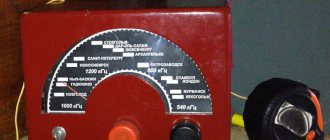
The voltage for the GK-71 pentode is 20 volts, but the current must be at least 3.5 amperes. In general, the heat consumes 70 watts. A domestic transformer TN54-220-50 was purchased on the market for a symbolic sum. If the windings are connected correctly, you can get 85 W from it without any financial costs.
The next element is a high-voltage transformer from a microwave oven, the bourgeoisie call it MOT.
The voltage at its output is 2 kilovolts, the current is about 1 ampere. It’s quite a powerful and dangerous thing that can send you to a meeting with its creator, so don’t get carried away.
Below is a short list of elements needed to assemble the structure:
2 oil capacitors from the same microwave, voltage 2.1 kV, capacity 0.95 µF. The HYR-1x diode assembly, its maximum permissible voltage is 12 kV, current 500 mA, according to the passport, can withstand a pulse current of up to 30 amperes. A real beast of its own. Resistors of the PEV type are 10-20 W, you can use any other analogues of bourgeois production.
Resonant high-frequency capacitor type KVI-3, voltage can vary from 5 to 20 kV; several such comrades with different capacitance ratings on board were purchased for setup. To wind the inductor, a stranded copper wire of the PVA type, with a cross-section of 1.5 square, was purchased. Length is about 16 meters. The communication coil has a different color and is 10 meters long. All wires are taken in length with a margin.
Switches for switching power parts, taken with a permissible current of up to 15 amperes, don’t ask why so much, the reserve doesn’t put a strain on your pocket.
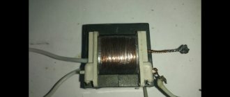
Now there is a secondary high-voltage winding, also known as a “resonator”.
Winding this part requires a lot of time and patience. Here, 0.2 mm thick varnished copper wire is used, wound turn to turn on a cardboard base from cling film. Pipe diameter 55 mm. The winding height was 35 cm. The turns should not intersect or overlap each other.
After winding procedures, the result should be covered with a layer of dielectric to avoid breakdown of the winding.
Epoxy is applied in two layers for reliability. The result will be a glossy pipe that shimmers in the light, which will take away part of your precious life. The second duplicate coil was wound on a plastic sewer pipe with a diameter of 50 mm. PVC is a more reliable dielectric, we will see this soon. The frame for the inductor was taken from the same cardboard only with a larger diameter, approximately 80 mm.
To carry out further work, it is necessary to place transformers, capacitors and other nonsense as compactly as possible on some kind of strong base.
Chipboard sheets have been lying around idle for a long time, so you should mark them and use a jigsaw, the work and sounds of which have a noble effect on the lives of your neighbors, this is especially true on weekends.
The structure will be two-story.
Transformers with capacitors will be placed below, and the Pentode and the Tesla coil itself will be placed on top. I thought for a long time about how to connect the first floor with the second, I decided to use wooden caps. Reliability here, of course, blushed and went to drink following her conscience. Some kind of jelly. We put on rose-colored glasses and cut out a hole for the radio lamp. Then we make holes for the wires on the reverse side.
Now about the inductor.
Now we don’t know exactly how many turns are needed, we’re winding 40, but when tuning it we still have to wind it down to find resonance. The feedback winding is wound in the same direction as the inductor. The number of turns is half as much, that is, 20. This ratio is found in many Tesla tube coils.
A moment that I didn’t quite understand.
In some circuits, the coupling winding is located at the bottom of the Tesla transformer, where the largest currents develop, and in some, above the inductor. I don’t know which placement option is better, but in this scheme it is placed on top.
We were unable to find a socket for installing the pentode; it is quite a rare thing, so the mounting alternative is a terminal block for a wire with a hole diameter of 4 mm. The clamps in it perfectly fix the pentode legs. Plywood, which was a magnet on the refrigerator door, was used as a decorative stand.
Now it's time to connect the wires to the filament transformer and see if everything works.
We apply power and observe the ammeter readings. 3 amperes, as the passport prescribed. As it warms up, current consumption drops slightly. Unfortunately, the camera was unable to convey all the beauty of the red-hot threads inside this glass eggplant. A hefty lamp... Well, they knew how to make it!
The whole circuit of the device is quite simple and looks something like this:
The alternating high voltage from the moto is rectified through a diode and charges the capacitors from the microwave; they are connected in series to increase the operating voltage.
In this case, the total capacitance is half a microfarad. The oscillatory circuit of the inductor is connected to the anode of the lamp through an inductor consisting of 10 turns. All control grids of the GK71 lamp are connected together, from this moment the pentode turns into a triode. The self-oscillator circuit begins to operate at very low voltages at the input of the moto. A 2.2 nF capacitor at the output of the filament transformer serves to filter interference and high-frequency emissions, although the first = the second, the second = the first, something like that. We pay attention to the connection of the windings in the primary circuit. The point is the bottom terminal of the winding.
In principle, the assembly turned out to be quite compact.
Her work can easily be demonstrated in physics lessons, remembering the life of that dude, thanks to whom we have alternating voltage in our sockets.
The Tesla transformer requires good grounding.
The battery is not the best solution for these cases, but in the absence of anything more suitable, this will do. The contact must be reliable; three meters of wire should be enough to reach anywhere within one room.
In new houses, this trick may not work due to metal-plastic pipes in the heating system. Therefore, we check the presence of voltage between the phase and the ground, it should be 220 volts. Some use grounding through grounding, which is also a suitable option. Between zero and ground there is a potential of 3.7 volts, Kreosan recently talked about how you can steal electricity in a similar way, charge your phone and light light bulbs, but I forgot to mention the fact that modern digital meters count energy consumption both by phase and by zero. The most you will win is a visit from the inspector to your home.
So, turn on the power to the incandescent circuit.
The lamp comes into operation quite quickly, 5 seconds is enough for this task.
The second switch supplies power to the motor. Under no circumstances should high voltage be applied to the anode of the lamp without the filament being turned on.
The input voltage on the motor is regulated using LATR, it provides voltage from zero to 220 volts. An indispensable thing when working with such schemes. We increase the voltage and see that the generator is working. With the advent of a high-frequency electric field, the LED lamp mounted under the shelf begins to glow and blink a little.
A small streamer appeared at the tip of the screwdriver, which serves as a terminal for the lightning to exit.
As the voltage increases, its size increases, but the discharges are somehow thin and not impressive. Let's change the position of the communication winding, move it slightly down. Let's see what has changed at work. We gradually increase the voltage... we see that the discharges have become more confident, thicker, longer and brighter. The sound is quite impressive, similar to the dull roar of a sports car.
The search for resonance was carried out either by unwinding the turns or by selecting a resonant capacitor.
He began to unwind the turns. The increase in discharge power indicates that we are on the right track. The discharges are more powerful, thicker, longer, the most interesting thing happened when I began to increase the capacity of the resonant capacitor. The discharge increased and began to decrease before our eyes. There was a smell of burnt paper.
A detailed examination revealed that the cardboard had begun to burn through.
And if a small burnout appears, then it gradually turns into a large one, since the carbon resulting from the combustion of something becomes an excellent conductor. In general, this is gangrene, which must be amputated immediately. We get rid of the problem area using a hacksaw. A couple of minutes, the problem is solved, and the hand is pumped up.
Since the resonant circuit has changed its characteristics by reducing the length of the secondary coil, we again rewind and unwind the turns of the primary. Power increases. The mood is excellent, a couple of seconds of joy and the structure begins to fail. The secondary breaks through to the primary. The windings are placed too close to each other. There were assumptions that this could happen, but not so quickly. The first day of setup, and many hours of work are thrown into the trash. If desired, this pipe can be cut in half and, for example, made a Brovin kacher on a transistor.
At first I wanted to isolate the secondary waste using a plastic bottle, but as practice shows, this collective farm does not lead to anything good.
We put on our sneakers and head to the nearest plumbing store to get a 10-centimeter drain pipe. This diameter will reduce the coupling coefficient of the windings, which is good in this design. The dielectric properties of such a cylinder are much better than those of ordinary cardboard.
We wrap a layer of paper over the pipe, and lay the turns of the inductor and communication windings on it.
The paper allows you to easily move the windings along the entire length of the pipe. It is convenient to install the coils on plugs; they come from the same plumbing store and allow you to maintain the alignment of the entire resonant circuit. A little effort and the structure is ready for use again. We repeat the switching procedure. First, we supply power to the filament, wait a couple of seconds, and then turn on the anode voltage. It is now at zero and is regulated by a laboratory autotransformer. Turn it on and gradually increase the voltage.
With increasing coupling coefficient, the discharges became larger and more beautiful.
At this point it was probably worth ending the post, the circuit worked, we saw the discharge. But according to tradition, this is where everything is just beginning.
For final and more correct operation, the self-oscillator must be configured on an oscilloscope.
We will configure the system according to the maximum signal amplitude. We will not connect the oscilloscope probe directly to the circuit; to configure it, we will place it at the torus level and watch the on-air signal. The entire pickup, shape, frequency and amplitude of the signal will be displayed on the oscilloscope screen. In this scheme, this information for configuration will be more than enough. Turn on the heat. Apply anode voltage. We regulate the voltage with an autotransformer... but for some reason nothing happens... let's figure out what's wrong!? Yeah, we forgot to connect the grounding, sometimes we screw it into place and repeat the switching procedure. We turn the knob and the signal comes to life. This is our indicator in the world of customization. The input voltage on the moto is only 50 volts, great, we don’t need discharges in the air now.
An alternative to detecting high-frequency fields is an ordinary neon light bulb.
It will not be possible to determine the signal amplitude, but you can judge the performance of the device as a whole, correct or not - that’s another matter.
So, during the setup process we were able to identify two interesting operating modes.
The first is a smoothly decaying pulse with a small amplitude, in contrast to the second mode. Now we transfer the wires to different turns of the inductor and observe how the signal changes. Attention, a question for experts. Which mode of the self-oscillator gives the largest discharges: option “a” - with a smoothly decaying signal, but a small amplitude, or option “b” - with a large amplitude, but a short pulse?
Tuning resonance using capacitors.
These samples have different capacities, how to choose the right one? It’s simple, we alternately connect the capacitors in parallel with the inductor and look at the signal. You need to be careful here, large currents develop here that can cause fatality to your hand. Nobody needs dead electronic engineers. If the capacitance is too large, it will simply extinguish the entire amplitude of the signal.
At the beginning of the issue, I promised to tell you why such massive contacts on capacitors are needed.
During operation, especially at resonance, huge currents develop in the inductor, on the order of several hundred amperes; if such a current flows through the thin legs of a conventional capacitor, they will simply burn out like a jumper in a fuse. In this circuit, the KVI3 capacitor of 1500 pF 10 kV has taken root well. Year of manufacture 1978, a rarity of its kind, 10 years older than me.
The self-oscillator circuit operates in forced interruption mode with a mains frequency of 50 Hz; if you stretch the damped oscillations over time, you can calculate the operating frequency of the self-oscillator. Let's synchronize this old junk and start doing the calculations.
Now, the division time switch on the oscilloscope is set to 0.5 µs. This means that one cell on the screen scale is equal to 0.5 µs. One period of a sine wave takes 5 cells, therefore 5 multiplied by 0.5 equals 2.5 µs. Frequency is found using the formula: 1 divided by period. We count. 1/2.5 µs equals 0.4 MHz, which equals 400 kHz. Hence the conclusion that the resonant frequency of the tuned Tesla coil is 400 kHz.
The calculations could be more accurate with modern equipment, but for this scheme it is simply not needed.
After setting, we adjust the positions of the inductor and the coupling winding so that the signal amplitude on the oscilloscope is maximum. At this stage, setting up a lamp tesla coil can be considered exhaustive. The consumption of the power part of the circuit without a filament circuit is 720 W.
There is something amazing in the work of lamps; when you take them in your hands, you return to those distant warm times.
Transistors and other modern electronics eventually become boring and boring. You can look at the lamp forever, well, or 1000 hours until the electron emission disappears and the cathode becomes depleted. Now it's time to see how it all works.
During operation of the circuit, the lamp does not overheat and can work for a long time, say 10 minutes without interruption. But there are craftsmen who install large-scale assemblies of microwave capacitors at the output of the motor, the power of the circuit increases, and the lamp begins to work at the limit of its capabilities. Naturally, the graphite anode of the lamp heats up to red, and the cathode consumes its resource. This mode will work, but not for long.
To increase the service life of the lamp at high powers, breakers are used.
This is roughly a switch that briefly starts the generator on a Tesla. A second of work, a second of rest, something like that. Modes can of course be changed.
The glow of various light bulbs in high-frequency electric fields is generally a separate topic; some samples are so beautiful that they qualify for a separate post.
We’ve heard that you can tint the color of fire with various salts, now let’s check this in practice.
To do this, take ordinary table salt and dilute it with a small amount of water. We apply the resulting porridge to the electrode. Sodium ions should tint the lightning orange, we'll see about that now.
This design is easy to repeat and simple to set up.
There are no expensive parts in it, although the price is a relative matter, the cost of all elements is approximately 65 bucks, not including LATR for adjusting the input voltage in the anode circuit.
In one of the next posts we will look at a semiconductor system, there we will learn how resonance is calculated, how to control iron and other nonsense little known to a normal person.
For reference.
Filming today's episode, including post-production, text writing and other processes, took 2 months. This can be called a quick release. In the comments you often write that we should film material in the field of physics and electronics, this is what is happening now, but there is a flip side to the coin, time. Now releases will be published less frequently than usual, I hope you understand everything.
As popular wisdom says: work and labor will grind everything down.
Full video of the project on YouTube Our Instagram
Design and assembly
The Tesla transformer was patented in 1896 and is simple in design. It includes:
- A primary coil with a copper core winding with a cross-section of 6 mm², in an amount sufficient for 5-7 turns.
- A secondary coil made of dielectric material and wire with a diameter of up to 0.5 mm and a length sufficient for 800-1000 turns.
- Hemispheres of the arrester.
- Capacitors.
- A protective ring made of copper core, like on the primary winding of a transformer.
The peculiarity of the device is that its power does not depend on the power of the power source. The physical properties of air are more important. The device can create oscillatory circuits using various methods:
- using a spark gap arrester;
- using a transistor oscillation generator;
- on lamps.
To make a Tesla transformer with your own hands you will need:
- For the primary winding - 3 m of thin copper tube with a diameter of 6 mm or a copper core of the same diameter and length.
- To assemble the secondary winding, you need a PVC pipe with a diameter of 5 cm and a length of about 50 cm and a PVC threaded fitting for it. You also need a copper wire coated with varnish or enamel with a diameter of 0.5 mm and a length of 90 m.
- Metal flange with an internal diameter of 5 cm.
- Various nuts, washers and bolts.
- Arrester.
- Smooth hemisphere for the terminal.
- You can make the capacitor yourself. It will require 6 glass bottles, table salt, rapeseed or vaseline oil, and aluminum foil.
- A power supply capable of delivering 9kV at 30mA will be required.
The Tesla transformer circuit is easy to implement. There are 2 wires coming from the transformer with a spark gap connected. Series-connected capacitors are connected to one of the wires. At the end is the primary winding. The secondary coil with a terminal and a grounded protection ring is located separately.
Description of how to assemble a Tesla coil at home:
- A secondary winding is made by first securing the edge of the wire to the end of the pipe. It should be wound evenly, without allowing the wire to break. There should be no gaps between the turns.
- When finished, wrap the top and bottom of the wrapping with masking tape. After this, coat the winding with varnish or epoxy resin.
- Prepare 2 panels for the bottom and top bases. Any dielectric material, a sheet of plywood or plastic, will do. Place a metal flange in the center of the lower base and secure it with bolts so that there is space between the lower and upper bases.
- Prepare the primary winding by twisting it into a spiral and securing it to the upper base. After drilling 2 holes in it, bring the ends of the tube into them. It should be secured in such a way as to prevent contact of the windings and at the same time maintain a distance of 1 cm between them.
- To make a spark gap you will need to place 2 bolts opposite each other in a wooden frame. The calculation is made that when moving they will play the role of a regulator.
- Capacitors are manufactured as follows. Glass bottles are wrapped in foil and salted water is poured into them. Its composition should be the same for all bottles - 360 g per 1 liter of water. They pierce the covers and insert wires into them. The capacitors are ready.
- All nodes are connected according to the scheme described above. Be sure to ground the secondary winding.
- The total number in the primary winding should be 6.5 turns, in the secondary - 600 turns.
The described sequence of actions gives an idea of how to make a Tesla transformer yourself.
How to make a Tesla coil at home with your own hands
On the Internet you can find a lot of information on how to make a musical or mini Tesla coil with your own hands. But we will tell you and clearly show with illustrations how to make a simple 220 Volt Tesla coil at home.
Since this invention was created by Nikola Tesla for experiments with high-voltage charges, it contains the following elements: a power source, a capacitor, 2 coils (the charge will circulate between them), 2 electrodes (the charge will slip between them).
The Tesla coil is used in a variety of devices: from television and particle accelerators to toys for children.
To get started you will need the following parts:
- power supply from neon signs (supply transformer);
- several ceramic capacitors;
- metal bolts;
- hair dryer (if you don’t have a hair dryer, you can use a fan);
- varnished copper wire;
- metal ball or ring;
- toroidal shapes for coils (can be replaced with cylindrical ones);
- safety bar;
- chokes;
- ground pin.
Creation should occur in the following stages.
Design
First, you need to decide what size the coil should be and where it will be located.
If finances allow, you can create a huge generator at home. But you should remember one important detail : the coil creates many spark discharges that greatly heat the air, causing it to expand. The result is thunder. As a result, the created electromagnetic field is able to disable all electrical appliances. Therefore, it is better to create it not in an apartment, but somewhere in a more secluded and remote corner (garage, workshop, etc.).
If you want to determine in advance how long the arc your coil will produce or the power of the required power supply, make the following measurements: divide the distance between the electrodes in centimeters by 4.25, square the resulting number. The final number will be your power in Watts. And vice versa - to find out the distance between the electrodes, the square root of the power must be multiplied by 4.25. A Tesla coil that will be able to create an arc one and a half meters long will require 1,246 watts. And a device with a one-kilowatt power supply can make a spark 1.37 meters long.
Next we study the terminology. To create such an unusual device, you will need to understand highly specialized scientific terms and units of measurement. And in order not to make a mistake and do everything correctly, you will have to learn to understand their meaning and significance. Here is some information that will help:
- What is electrical capacitance ? This is the ability to accumulate and hold an electrical charge of a certain voltage. Something that stores electrical charge is called a capacitor. Farad is a unit of measurement of electrical charges (F). It can be expressed as 1 ampere second (Coulomb) multiplied by a volt. Typically, capacitance is measured in millionths and trillionths of farads (micro- and picofarads).
- What is self-induction? This is the name for the phenomenon of the occurrence of EMF in a conductor when the current passing through it changes. High-voltage wires carrying low-ampere current have high self-inductance. Its unit of measurement is henry (H), which corresponds to a circuit in which changing current at a rate of one ampere per second creates an emf of 1 Volt. Typically, inductance is measured in milli- and microhenry (parts per thousand and parts per million).
- What is resonant frequency ? This is the name of the frequency at which losses in energy transmission will be minimal. In a Tesla coil, this will be the frequency of minimum losses when transmitting energy between the primary and secondary windings. Its unit of measurement is hertz (Hz), that is, one cycle per second. Typically, resonant frequency is measured in thousands of Hertz or kilohertz (kHz).
Gathering the necessary parts
We have already written above what components you will need to create a Tesla coil at home. And if you are a radio amateur, you will certainly have some (or even all) of these.
Here are some features of the necessary parts:
- the power source must supply, through an inductor, a storage or primary oscillating circuit consisting of a primary coil, a primary capacitor and a spark gap;
- the primary coil should be located near the secondary coil, which is an element of the secondary oscillating circuit, but the circuits should not be connected by wires. As soon as the secondary capacitor accumulates a sufficient charge, it will immediately begin to release electrical charges into the air.
Making a Tesla Coil
- Selecting a transformer . It is the supply transformer that will decide what size your coil will be. Most of these coils are powered by transformers capable of delivering current from 30 to 100 milliamps at a voltage of five to fifteen thousand volts. You can find the required transformer at the nearest radio market, on the Internet, or remove it from a neon sign.
- Making a primary capacitor . It can be assembled from several smaller capacitors, connecting them in a circuit. Then they will be able to accumulate equal shares of charge in the primary circuit. True, it is necessary that all small capacitors have the same capacity. Each of these small capacitors will be called composite.
You can purchase a small capacitor on the radio market, on the Internet, or remove ceramic capacitors from an old TV. However, if you have golden hands, you can make them yourself from aluminum foil using plastic film.
To achieve maximum power, the primary capacitor must be fully charged every half power cycle. For a 60 Hz power source, charging needs to occur 120 times per second.
- We are designing a spark gap . To make a single arrester, use a minimum of six millimeter (thick) wire. Then the electrodes will be able to withstand the heat that is generated during charging. In addition, it is possible to make a multi-electrode or rotary spark gap, and also to cool the electrodes by air blowing. An old household vacuum cleaner is perfect for these purposes.
- We make the winding of the primary coil . We make the coil itself from wire, but you will need a form around which you will have to wind the wire. For these purposes, varnished copper wire is used, which can be bought at an electronics store or simply removed from any old unnecessary electrical appliance. The shape around which we will wind the wire should be conical or cylindrical (plastic or cardboard tube, old lampshade, etc.). Due to the length of the wire, the inductance of the primary coil can be adjusted. The latter should have low inductance, so it should have a small number of turns. The wire for the primary coil does not have to be solid - several can be fastened together to adjust the inductance during assembly.
- We assemble the primary capacitor, spark gap and primary coil into one circuit . This circuit will form the primary oscillatory circuit.
- We make a secondary inductor . Here we also need a cylindrical shape where we need to wind the wire. This coil must have the same resonant frequency as the primary, otherwise losses cannot be avoided. The secondary coil should be higher than the primary one, because it will have more inductance and will prevent the secondary circuit from discharging (which can lead to the primary coil burning out). If there is a shortage of materials to create a large secondary coil, a discharge electrode can be made. This will protect the primary circuit, but will cause that electrode to take the majority of the shocks, resulting in no visible shocks.
- We create a secondary capacitor, or terminal . It should have a rounded shape. Typically this is a torus (donut-shaped ring) or sphere.
- We connect the secondary capacitor and the secondary coil . This will be the secondary oscillating circuit, which should be grounded away from the house wiring that powers the Tesla coil source. What is it for? This will prevent high-voltage currents from wandering through the wiring of the house and subsequent damage to any connected electrical appliances. For separate grounding, it will be enough to simply drive a metal pin into the ground.
- We make pulse chokes . You can make such a small coil that can prevent the spark gap from breaking the power source by winding copper wire around a thin tube.
- We collect all the details into a single whole . We place the primary and secondary oscillatory circuits side by side, and connect the supply transformer to the primary circuit through chokes. That's all! To use the Tesla coil for its intended purpose, just turn on the transformer!
If the primary coil is too large in diameter, you can place the secondary coil inside the primary.
And here is the entire sequence of assembling a Tesla coil in pictures:
Switching on, checking and adjusting
Before turning on, move electronic devices away from the test site to prevent damage. Remember electrical safety! To launch successfully, perform the following steps in order:
- We set the variable resistor to the middle position. When applying power, make sure there is no damage.
- Visually check the presence of the streamer. If it is missing, we bring a fluorescent light bulb or incandescent lamp to the secondary coil. The glow of the lamp confirms the functionality of the “Tesla transformer” and the presence of an electromagnetic field.
- If the device does not work, first of all we swap the leads of the primary coil, and only then we check the transistor for breakdown.
- When you turn it on for the first time, monitor the temperature of the transistor; if necessary, connect additional cooling.
Powerful Tesla Coil
Distinctive features of the powerful Tesla transformer are high voltage, large dimensions of the device and the method of producing resonant oscillations. Let's talk a little about how it works and how to make a Tesla spark-type transformer.
The primary circuit operates on alternating voltage. When turned on, the capacitor charges. As soon as the capacitor is charged to the maximum, a breakdown of the spark gap occurs - a device of two conductors with a spark gap filled with air or gas. After the breakdown, a series circuit of a capacitor and a primary coil is formed, called an LC circuit. It is this circuit that creates high-frequency oscillations, which create resonant oscillations and enormous voltage in the secondary circuit (Fig. 6).
If you have the necessary parts, you can assemble a powerful Tesla transformer with your own hands, even at home. To do this, it is enough to make changes to the low-power circuit:
- Increase the diameters of the coils and the cross-section of the wire by 1.1 - 2.5 times.
- Add a toroid-shaped terminal.
- Change the DC voltage source to an alternating one with a high boost factor that produces a voltage of 3–5 kV.
- Change the primary circuit according to the diagram in Figure 6.
- Add reliable grounding.
Tesla spark transformers can reach a power of up to 4.5 kW, therefore creating large-sized streamers. The best effect is obtained when the frequencies of both circuits are equal. This can be realized by calculating parts in special programs - vsTesla, inca and others. You can download one of the Russian-language programs from the link: https://ntesla.at.ua/_fr/1/6977608.zip.
alternative energy
Operating principle of a synchronous generator
Supporters of traditional physics and energy deny the possibility of creating a workable generator, using existing concepts, laws and definitions. A lot of evidence is given that such devices cannot exist in practice, since they contradict the law of conservation of energy.
Proponents of the “conspiracy theory” are convinced that calculations of the generator exist, as well as its working prototypes, but they are not presented to science and the general public, since they are not profitable for modern energy companies and can cause an economic crisis.
Enthusiasts have repeatedly attempted to create a generator; they have built many prototypes, but for some reason reports on the work regularly disappear or disappear. It has been noted that network resources dedicated to alternative energy are periodically closed.
This may indicate that the design is actually functional, and it is possible to create a generator with your own hands even at home.
Components and operating principle
All Tesla transformers, due to a similar operating principle, consist of identical blocks:
- Power supply.
- Primary circuit.
- Secondary circuit.
The power supply provides the primary circuit with voltage of the required magnitude and type. The primary circuit creates high-frequency oscillations that generate resonant oscillations in the secondary circuit. As a result, a current of high voltage and frequency is formed on the secondary winding, which tends to create an electrical circuit through the air - a streamer is formed.
The choice of primary circuit determines the type of Tesla coil, power source and size of the streamer. Let's focus on the semiconductor type. It features a simple circuit with accessible parts and a low supply voltage.
Selection of materials and parts
We will search and select parts for each of the above structural units:
- Power supply requires 12 - 19 V DC voltage. A machine battery, a laptop charger or a step-down transformer with a diode bridge will be suitable to produce direct current.
- Let's find the details for the primary circuit:
— Variable resistor R1 with a nominal value of 50 kOhm. For successful assembly, do not forget to connect the two contacts of this resistor according to the diagram.
— Resistor R2 with a nominal value of 75 Ohms.
— Transistor VT1 D13007 or a Soviet analogue with an NPN structure.
— A radiator for cooling the transistor can be found on powerful transistors in faulty equipment. Size directly affects the quality of cooling.
— Primary winding of the Tesla transformer. The conductor can be a simple copper tube or wire with a diameter of 0.5–1 cm. The winding is made flat, cylindrical or conical (Fig. 2).
- The secondary circuit consists of a coil and, if necessary, a terminal. The winding is made with wire with a diameter of 0.1 to 0.3 mm². The wire can be wound on a dielectric PVC tube. The length of the tube is 25–40 cm, and the diameter is 3–5 cm. It should be wound turn to turn: without intersections or gaps. To prevent the winding from slipping and unwinding, it is recommended to secure the wound sections. The number of turns is from 700 to 1000 (Fig. 3).
After winding, we insulate the secondary coil with paint, varnish or other dielectric. This will prevent the streamer from getting into it.
Terminal – additional capacity of the secondary circuit, connected in series. For small streamers it is not necessary. It is enough to bring the end of the coil up 0.5–5 cm.
After we have collected all the necessary parts for the Tesla coil, we begin to assemble the structure with our own hands.
Self-production
So, the simplest way to make a Tesla coil for dummies with your own hands. Often on the Internet you can see amounts exceeding the cost of a good smartphone, but in reality, a 12V transformer, which will make it possible to enjoy turning on the lamp without using an outlet, can be assembled from a heap of garage trash.
What should happen in the end?
You will need enameled copper wire. If you can’t find an enamel one, then you will additionally need regular nail polish. The wire diameter can be from 0.1 to 0.3 mm. To maintain the number of turns you will need about 200 meters. You can wind it on a regular PVC pipe with a diameter of 4 to 7 cm. Height is from 15 to 30 cm. You will also have to buy a transistor, for example, D13007, a pair of resistors and wires. It would be nice to get a computer cooler that will cool the transistor.
You might be interested in How to measure voltage
Now you can start assembling:
- cut 30 cm of pipe;
- wrap the wire around it. The turns should be as close to each other as possible. If the wire is not coated with enamel, varnish it at the end. From the top of the pipe, thread the end of the wire through the wall and bring it up so that it sticks out 2 cm above the installed pipe.;
- make a platform. A regular chipboard board will do;
- you can make the first coil. You need to take a 6 mm copper pipe, bend it into three and a half turns and secure it to the frame. If the tube diameter is smaller, then there should be more turns. Its diameter should be 3 cm larger than the second coil. Attach to the frame. Immediately attach the second coil;
- There are quite a few ways to make a toroid. Copper tubes can be used. But it’s easier to take a regular aluminum corrugation and a metal crossbar for fastening to the protruding end of the wire. If the wire is too flimsy to hold the toroid, you can use a nail, like in the picture below;
- Don't forget about the protective ring. Although if one end of the primary circuit is grounded, it can be abandoned;
- When the design is ready, the transistor is connected according to the circuit, attached to a radiator or cooler, then you need to supply power and the installation is completed.
The first coil can be made flat, as in the picture.
Many people use a regular Duracell crown to power the installation.
DIY Tesla transformer, simple circuit
Design and assembly
We carry out the assembly according to the simplest scheme in Figure 4.
We install the power supply separately. The parts can be assembled by hanging installation, the main thing is to avoid short circuits between the contacts.
When connecting a transistor, it is important not to mix up the contacts (Fig. 5).
To do this, we check the diagram. We tightly screw the radiator to the transistor body.
Assemble the circuit on a dielectric substrate: a piece of plywood, a plastic tray, a wooden box, etc. Separate the circuit from the coils with a dielectric plate or board with a miniature hole for the wires.
We secure the primary winding so as to prevent it from falling and touching the secondary winding. In the center of the primary winding we leave space for the secondary coil, taking into account the fact that the optimal distance between them is 1 cm. It is not necessary to use a frame - a reliable fastening is enough.
We install and secure the secondary winding. We make the necessary connections according to the diagram. You can see the operation of the manufactured Tesla transformer in the video below.
DIY Tesla generator for 220 volts
Materials:
- dielectric base for the screen (thick cardboard, plastic panel, plywood);
- foil material;
- the wire;
- electrolytic capacitor (voltage from 180 to 400 V);
- To regulate the voltage, it is possible to install a resistor (resistance).
A similar set of materials is almost always available in the house.
Grounding
It is enough to connect the wire to a metal rod and bury it in the ground. At the dacha, you can throw a wire on any metal pipe in the ground. In the apartment, the wire is connected to water supply pipes, gas metal pipes, and the grounding phase in the socket.
Tesla generator screen
Receives light radiation with positively charged particles from sources (from a light source, the sun).
It’s not difficult to make; just cover the dielectric panel with foil. The layers are overlapped. The larger the screen is to trap positively charged particles, the higher the voltage in the circuit. Several shielded surfaces are also connected to each other. They form a chain of screens for Tesla's fuel-free generator. According to the expansion of the area of the collecting panels, it is necessary to increase the capacitance of the capacitor and the dissipation power of the resistor.
It is necessary to connect and connect the elements of the Tesla fuel-free generator circuit. One wire (contact) is connected to the foil screen, the second leads from grounding. The contacts are closed at the poles of the capacitor. The moment the circuit is closed, the battery begins charging.
Materials for fuel-free Tesla generator
Tesla's fuel-free generator is ready. You can check it by connecting the contacts of the light bulb to a battery, it will light up.
Self-assembly diagram
This scheme has a minimum of elements, which does not make our task any easier. After all, for it to work, it is necessary not only to assemble it, but also to configure it. Let's start with ILOs.
There is such a transformer in the microwave. It is a regular power transformer with the only difference that its core operates in a mode close to saturation.
Assembly diagram of a homemade Tesla transformer.
This means that despite its small size, it has a power of up to 1.5 kW. However, there are also negative aspects to this mode of operation. This includes a high idle current, about 2-4 A, and strong heating even without a load; I am silent about heating with a load. The usual output voltage of the MOT is 2000-2200 volts with a current of 500-850 mA.
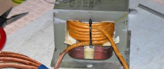
MOT for Tesla transformer.
For all MOTs, the “primary” is wound at the bottom, the “secondary” at the top. This is done to ensure good insulation of the windings.
On the “secondary”, and sometimes on the “primary”, the filament winding of the magnetron is wound, about 3.6 volts.
Moreover, between the windings you can see two metal jumpers. These are magnetic shunts.
Their main purpose is to close on themselves part of the magnetic flux created by the “primary”.
Thus, limit the magnetic flux through the “secondary” and its output current at a certain level.
Attention! We ask amateurs to refuse this work! Dangerous, high voltage, lethal! Although the voltage is small compared to the lineman, the current strength, a hundred times greater than the safe limit of 10 mA, will reduce the chances of staying alive to almost zero.
KAPs mean high-voltage ceramic capacitors (series K15U1, K15U2, TGK, KTK, K15-11, K15-14 - for high-frequency installations!).
HF filter for homemade Tesla.
HF filter: respectively, two coils that perform the function of filters from high frequency voltage.
Each contains 140 turns of varnished copper wire 0.5 mm in diameter.
A spark plug, which is needed for switching power and exciting oscillations in the circuit.
If there is no spark switch in the circuit, then there will be power, but there will be no oscillations. And the power supply begins to siphon through the primary - and this is a short circuit!
Spark plug for a homemade Tesla transformer.
As long as the spark switch is not closed, the caps are charging. As soon as it closes, oscillations begin. Therefore, they install ballast in the form of throttles - when the spark plug is closed, the throttle prevents the flow of current from the power supply, it charges itself, and then, when the spark gap opens, it charges the caps with redoubled anger.
Finally, the turn has come to the Tesla transformer itself: the primary winding consists of 7-9 turns of wire of a very large cross-section.
However, a plumbing copper pipe will do. The secondary winding contains from 400 to 800 turns, here you need to adjust.
Do-it-yourself finished Tesla transformer coil.
Power is supplied to the primary winding. The secondary has one terminal reliably grounded, the second is connected to the TORU (lightning emitter).
The torus can be made from ventilation corrugation. That's all. Remember to be safe and good luck with your DIY build.
What it is
In fact, a fuel-free electric generator is a perpetual motion machine that does not require additional resources to operate. Obtaining free energy is the dream of humanity, which will become the impetus for the reconstruction of social relations of society and will lead to an evolutionary leap in development.
Ether Tesla
The idea of obtaining alternative energy could be realized by a Tesla generator, which draws energy from the ether.
Important. There is a lot of debate about whether ether exists. According to N. Tesla, it is the lightest gas, made up of almost imperceptibly small particles. They move at unimaginable speed. N. Tesla believed that each type of wave operates at its own frequency and in a certain environment. Ether is a medium for almost instantaneous transmission of electromagnetic waves. Its field is capable of transmitting electromagnetic and gravitational waves over enormous distances.
Operating principle of a fuel-free generator
Ether is a source of unlimited energy. Electromagnetic waves permeate the atmosphere around us. The earth has a low energy potential, while light and sun rays have a high energy potential. If you install a trap between positively charged light particles and the negatively charged potential of the ground, you can generate an electric current. In this chain you need to insert a storage capacitor, for example, a lithium battery. It will capture and accumulate energy. When a power source is connected to the capacitor, the storage device will be discharged.
The main components of N. Tesla's fuel-free generator consist of:
- Receiver located above the ground.
- Storage capacitor.
- Grounding.
You may be interested in this Digital electronic electricity meter
Note! A fuel-free electric generator is based on obtaining electric current from the ether. Two differently charged potentials are used. The earth is a resource of negative electrons, light waves, including those from the sun, are positive. One of the electrodes is grounded, the other is displayed on a shielded screen. A capacitor is installed in the circuit as a storage device, which accumulates energy.
Scheme on how to make a fuel-free Tesla generator with your own hands
Application area
It is incorrect to assume that the Tesla transformer does not have wide practical applications. It is used to ignite gas discharge lamps and to detect leaks in vacuum systems. However, its main use today is cognitive and aesthetic. The table below shows the effects that occur during operation of a Tesla transformer.
Effects that occur during operation of a Tesla transformer.
This is mainly due to significant difficulties when it is necessary to control the selection of high-voltage power, or even more so, transfer it to a distance from the transformer, since in this case the device inevitably goes out of resonance, and the quality factor of the secondary circuit is also significantly reduced.
Generator circuits for 555
Then I decided to fundamentally change the circuit and make independent duration on the capacitor, diode and resistor. Many may consider this scheme absurd and stupid, but it works. The principle is this: the signal goes to the driver until the capacitor is charged (I think no one will argue with this). NE555 generates a signal, it goes through a resistor and a capacitor, and if the resistance of the resistor is 0 Ohm, then it goes only through the capacitor and the duration is maximum (as long as the capacitance is enough) regardless of the duty cycle of the generator. The resistor limits the charging time, i.e. The greater the resistance, the shorter the pulse will take. The driver receives a signal of shorter duration, but of the same frequency. The capacitor discharges quickly through a resistor (which goes to ground 1k) and a diode.
What is unique about the Tesla Coil?
The main difference of this invention is that its inventor was able to obtain a voltage exceeding 15 million volts at a frequency of several hundred kilohertz. This device looks incredibly strange, scary, but also beautiful at the same time: the absence of an iron core, a thick outer layer of the primary winding and a thick inner layer of the secondary winding. But there are also disadvantages. For example, making a large turn while ensuring excellent thermal contact with the transformer core is quite difficult.
Many are trying to repeat the numerous unique experiments of the great genius. However, to do this, they will have to solve the most important problem - how to make a Tesla coil at home. But how to do that? Let's try to describe it in detail so that you can do it the first time.
What is needed to make a Tesla coil?
To make a Tesla coil at home, at our desk or even in the kitchen, we first need to stock up on everything we need. So, first we must find or purchase the following. The tools we need are:
- Soldering iron
- Glue gun
- Drill with thin drill bit
- Hacksaw
- Scissors
- Insulating tape
- Marker
To assemble the Tesla coil itself, you need to prepare the following:
- A piece of thick polypropylene pipe with a diameter of 20 mm.
- Copper wire with a diameter of 0.08-0.3 mm.
- A piece of thick wire
- Transistor type KT31117B or 2N2222A (can be KT805, KT815, KT817)
- Resistor 22 kOhm (you can take resistors from 20 to 60 kOhm)
- Power supply (Krona)
- Ping pong ball
- A piece of food foil
- The base on which the product will be mounted is a piece of board or plastic
- Wires for connecting our circuit
Having prepared everything you need, we begin making the Tesla coil.
What is a Tesla transformer used for?
Toy? Nothing like this. Using this principle, Tesla intended to build a global system of wireless energy transmission using ether energy. To implement such a scheme, two powerful transformers are needed, installed at different ends of the Earth, operating at the same resonant frequency.
In this case, there is completely no need for copper wires, power plants, or bills for paying for the services of monopoly electricity suppliers, since anyone anywhere in the world could use electricity completely unhindered and free of charge. Naturally, such a system will never pay for itself, since there is no need to pay for electricity. And if so, then investors are in no hurry to get in line to sell Nikola Tesla’s patent No. 645,576.
Description of the device
In short, a Tesla coil (CT) is a resonant transformer that creates a high-frequency current. There is information that in their experiments, the military brought the coil to a power of 1 THz.
Huge Tesla Coil
Here it is worth raising the following question: why did Tesla invent it? According to the records, the scientist was working on technology for wireless transmission of electricity. The question is extremely relevant for all humanity. In theory, with the help of ether, two powerful CTs located a couple of kilometers from each other will be able to transmit electricity. To do this, they must be tuned to the same frequency. There is also an opinion that CT can become a kind of perpetual motion machine.
The introduction of this technology will make all the nuclear power plants, thermal power plants, hydroelectric power stations and others available today simply unnecessary. Humanity will not have to burn solid fossils, be at risk of radiation contamination, or block river beds. But the answer to the question of why no one is developing this technology remains with conspiracy theorists.
Tabletop Tesla coil, sold today as a souvenir
Switching on, checking and adjusting
It is advisable to carry out the first start-up outdoors; you should also remove all household appliances away to prevent their breakdown. Remember safety precautions! To start, perform the following steps:
- They go through the entire chain of wires and check that bare contacts do not touch anywhere, and that all nodes are securely fastened. In the arrester, a small gap is left between the bolts.
- Apply voltage and observe the appearance of the streamer. If it is absent, a fluorescent lamp or incandescent lamp is brought to the secondary winding. It is advisable to secure them to a dielectric; a piece of PVC pipe will do. The appearance of a glow confirms that the Tesla transformer is working.
- If there is no glow, swap the leads of the primary coil.
If it doesn't work out the first time, don't despair. Try changing the number of turns in the secondary winding and the distance between the windings. Tighten the bolts in the arrester.
Modern look and new developments
Despite widespread interest in creating a free energy generator, they are still unable to displace the classical method of generating electricity from the market. Developers of the past, who put forward bold theories about significantly reducing the cost of electricity, lacked the technical perfection of the equipment or the parameters of the elements could not provide the desired effect. And thanks to scientific and technological progress, humanity is receiving more and more inventions that make the embodiment of a free energy generator already tangible. It should be noted that today free energy generators powered by the sun and wind have already been obtained and are actively being used.
But, at the same time, on the Internet you can find offers to purchase such devices, although most of them are dummies created with the aim of deceiving an ignorant person. And a small percentage of actually operating free energy generators, whether on resonant transformers, coils or permanent magnets, can only cope with powering low-power consumers; they cannot provide electricity, for example, to a private house or lighting in a yard. Free energy generators are a promising direction, but their practical implementation has not yet been implemented.
Generator or perpetual motion machine?
Most scientists deny the possibility of creating a free energy generator. It should be countered by the fact that even in the past, many modern achievements also seemed impossible. The fact is that science has many areas where research has been far from complete. This especially concerns issues of physical fields and energy. Those types of energy that are familiar to us can be felt and measured. But it is impossible to deny the presence of unknown species only on the grounds that there are no methods and instruments for their measurement and transformation.
For skeptics, any proposals for generators, schemes and ideas based on the conversion of free energy seem to be perpetual motion machines that operate without consuming energy, and are even capable of generating excess in the form of known energy, thermal or electrical.
We are not talking about perpetual motion machines here. In fact, the eternal generator uses free energy, which currently does not yet have a clear theoretical justification. What was light previously considered to be? And now it is used to generate electrical energy.
Free energy generator
Generator application
The Tesla generator and transformer were designed by the inventor as universal devices for wireless transmission of electrical energy. Nikola Tesla repeatedly conducted experiments confirming his theory, but, unfortunately, traces of the energy transfer reports were also lost or safely hidden, like many of his other designs. Developers have only recently begun to design devices to transmit energy, but only over relatively short distances (wireless phone chargers are a good example).
In an era of inevitable depletion of non-renewable natural resources (hydrocarbon fuels), the development and construction of alternative energy devices, including a fuel-free generator, is of great importance. A free energy generator with sufficient power can be used for lighting and heating homes. You should not refuse research citing a lack of experience and specialized education. Many important inventions were made by people who were professionals in completely different fields.
The concept of ether and Tesla's ideas
Now we know what a Tesla coil consists of. But what is the history of this invention? To answer this question, it is worth understanding what ether is.
Ether is a physical medium, a hypothetical substance or field that fills the space of the Universe. The ether is responsible for the propagation of electromagnetic and gravitational interactions.
At the moment, the theory of the ether is not used in modern physics, since after the advent of the theory of relativity, the need for the concept of “ether” simply disappeared.
However, new views on the concept of ether are emerging, and it should not be completely written off. Many scientists are still debating whether ether exists or not, and a new section has even appeared in physics that studies this issue (ether dynamics).
Nikola Tesla proved the existence of ether with his experiments. The scientist had an idea to use ether as a source of energy. Thus, Tesla wanted to abandon wired transmission of energy and transmit electricity throughout the world wirelessly through the ether. To do this, it was planned to install two giant coils at the Earth's poles.
Unfortunately, the direction Tesla chose was not developed at a deeper level. In addition, he was considered a strange scientist who never wanted to take the path of seeking the economic benefits of his research. In addition, another era was coming - the time of vacuum inventions.
Many of Tesla's archives were lost under mysterious circumstances. Even if Tesla found out how to obtain a practically inexhaustible source of energy, this information is not available now. The rare genius of Tesla was ahead of his time, and the world was simply not ready for his ideas.
Similar to a swing
To better understand the accumulation of large potential differences in a circuit, imagine a swing being rocked by an operator. The same oscillation circuit, and the person serves as the primary coil. The swing stroke is the electric current in the second winding, and the rise is the potential difference.
The operator swings and transmits energy. Over several times they accelerated greatly and rose very high; they concentrated a lot of energy in themselves. The same effect occurs with a Tesla coil, an excess of energy occurs, a breakdown occurs and a beautiful streamer is visible.
You need to oscillate the swing in accordance with the beat. Resonance frequency is the number of oscillations per second.
The length of the swing trajectory is determined by the coupling coefficient. If you swing a swing, it will swing quickly and move away exactly the length of a person’s arm. This coefficient is one. In our case, a Tesla coil with an increased coefficient is the same transformer.
A person pushes the swing, but does not hold it, then the coupling coefficient is small, the swing moves even further. It takes longer to swing them, but it doesn't require force. The coupling coefficient is greater the faster energy accumulates in the circuit. The potential difference at the output is less.
Quality factor is the opposite of friction, using the example of a swing. When friction is high, the quality factor is low. This means that the quality factor and coefficient are consistent for the highest swing height, or the largest streamer. In the transformer of the second winding of the Tesla coil, the quality factor is a variable value. It is difficult to reconcile the two values; it is selected as a result of experiments.
Rectangular pulse generator - circuit diagram
The next breaker was assembled on the UC3843, which is very often found in power supply systems, especially ATX, which is where I actually took it from. The circuit is also not bad and is not inferior the TL494 in terms of parameters. Here it is possible to adjust the frequency from 0 to 1 kHz and the duty cycle from 0 to 100%. This suited me too. But again these pickups from the coil ruined everything. Even shielding didn't help here. I had to refuse, although I assembled it well on the board...
Security measures
Once you have collected the CT, you need to take some precautions before launching. First, you need to check the wiring in the room where you plan to connect the transformer. Secondly, check the insulation of the windings.
It is also worth remembering the simplest precautions. The voltage of the secondary winding is on average 700A, 15A is already fatal for a person. Additionally, it is worth putting away all electrical appliances; if they get into the coil’s operating area, they are likely to burn out.
CT is a revolutionary discovery of its time, underestimated today. Today the Tesla transformer is used only for the entertainment of home electricians and in light shows. You can make a coil yourself using available materials. You will need a PVC pipe, several hundred meters of copper wire, a couple of meters of copper pipes, a transistor and a couple of resistors.
Sources
- https://ElectroInfo.net/praktika/katushka-tesla-transformator-samostojatelnaja-sborka-sobstvennymi-silami.html
- https://rusenergetics.ru/ustroistvo/katushka-tesla
- https://altenergiya.ru/poleznye-stati/kak-izgotovit-prostuyu-katushku-tesla-v-domashnix-usloviyax.html
- https://odinelectric.ru/knowledgebase/katushka-tesla-svoimi-rukami
- https://ProTransformatory.ru/sdelay-sam/katushka-tesla-svoimi-rukami
- https://katushkamishina.ru/tehnologiya/kak-izgotovit-katushku-tesla
- https://elektronchic.ru/elektrotexnika/katushka-tesla-svoimi-rukami.html