So, gentlemen, seeking to know the truth... After my publication of video files about the creation of an aircraft with the principle of flight on electric gravity at home, a lot of proposals were received with a request to “teach, tell how to do it, etc.” Somehow I didn’t get around to it until the last moment, and there wasn’t much time. Well, I have corrected myself and am telling you in detail. Remove wives, children, parents and grandparents from the house so that there are no extreme situations and people of the adult generation do not experience shock...
Safety rules... 1. The information being transmitted to you at this time can be used by you at your own peril and risk. 2. The device is powered by a high-frequency voltage of about 20,000 Volts, which is dangerous for the life of any person, so you take on the risk of using this craft in terms of preserving the life and health of yourself and those around you. 3. The device has exposed parts of the structure that are under high voltage. Due to the short circuit of oppositely polarized parts or wires of the structure, a short circuit occurs, with the formation of a high-voltage arc, which can lead to failure of the equipment used. You assume the risk of damage to the equipment used, as well as any consequences that occur due to a short circuit.
So the action itself...
Materials: 1. aluminum food foil 2. broom 3. “crocodile clips” - electric clips. 4. thread 5. BF glue 6. copper wire (I took diameter 0.1)
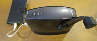
Required equipment: Working TV or monitor (THE CINESCOPE IS A MUST!)
The device is very critical of its weight. The use of broom fibers is due to the low weight of this material. Even the use of very thin strips of bamboo made the structure so heavy that the device did not take off. On the other hand, using TVs or monitors with a large picture tube as a power supply increases the likelihood of takeoff, because The larger the kinescope, the more voltage is applied to it.
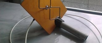
Manufacturing: Select the straightest core from the broom, cut it off and cut it lengthwise into 4 equal parts.
10 minutes) wrap the lower part of the frame 1
layer of aluminum foil
The upper wire of the device is powered from the “suction cup”, and the foil is powered from ground (I am powered from the power frame of the monitor, since it is grounded)
Source
The simplest do-it-yourself ekranolet
“Flying saucer” - do it yourself
Discolet? Anti-gravity? Whirlwind!
TM No. 5 for 1990 mentions an excerpt from a Sanskrit manuscript (“Samarangana Sutradhara”) containing a description of an aircraft - a “vimana”, which, according to some researchers, is nothing more than an “alien ship”. In this case, the “drawing” and “specification” recorded in ancient sources is another confirmation of paleocontact of the 3rd kind. But how close is all this to reality? In order for the further course of our reasoning to be clear, let us again read the description of the “vimana”:
“His body, made of light material, should be strong and durable, like a large flying bird. A device containing mercury and an iron heating device underneath should be placed inside. By means of the power which lies hidden in mercury and which sets in motion the carrying vortex, a person inside this chariot can fly long distances across the sky in a most amazing manner. Four strong containers for mercury should be placed inside. When they are heated by controlled fire from iron devices, the chariot will develop the power of thunder thanks to the mercury. And she immediately turns into a “pearl in the sky.”
So, “device with mercury”, “heating device”, “carrying vortex”. – what would that mean?
To begin with, let us recall that a heated vessel with mercury is the basis of the simplest diffusion vacuum pump (DVP). Is it not with his help that the ancients offer us to rise into the air?
Of the various pump designs, I settled on one that resembles this description - a toroidal type. Externally, it is a flat cylinder filled with liquid metal - mercury. Below it is a microwave oven (“heating device”) and electromagnetic coils—the stator. The latter creates a “running” magnetic field, causing the mercury to rotate, which becomes like the rotor of an asynchronous motor. Its rotation speed is several hundred thousand revolutions per minute. Under the influence of centrifugal force, mercury will take the shape of a donut-toroid, in which, due to uneven heating, an internal vortex motion also occurs (a spiral laid in a donut). Thanks to the “heating device”, mercury will go from a liquid to a state of supersaturated vapor.
Due to the rotation of the “steam donut” and the diffusion of specially supplied air into it, a very high vacuum is formed in the cylinder. Due to internal vortices in the “rotor”, the absorbed air ends up at its periphery and is squeezed towards the inner wall. Next, it is collected by a special jacket and thrown out through a jet nozzle. But this flow pushes the device forward, and something else lifts it off the ground.
Air enters the DVN from above. It rushes towards the air intake opening, and not in a straight line, but twisting in a spiral. Above the upper skin of the device, around the hole, its rotation speed will exceed 500 km/h, which will lead to a sharp drop in pressure and the formation of a vacuum zone. This, according to Bernoulli’s well-known law, means the emergence of a huge lifting force (“carrying vortex”), comparable to the force of a tornado.
In addition to the impressive lifting force and simplicity of design, toroidal-type DVNs (or, as I called them, “Tornado” DVNs) have at least two more valuable properties. Firstly, they have a significant gyroscopic effect. This is very important, because at high speeds diskettes have little stability. The arrangement of four gyroscope turbines will increase stability many times over. The second required quality is the ability of the pump to levitate due to the monstrous rotation speed of the mercury rotor. At the same time, its weight is compensated.
Let's return to the drawing in the Sanskrit manuscript. Obviously, a cross-section of the aircraft is shown. We see two DVN turbines with 4 pumps each. From an engineering point of view, the coaxial arrangement of pumps with a common air intake is optimal for increasing engine power for a given donut diameter.
Assembly instructions for the Kasatka-1 ekranoplan
oflin
Full Member
The two-seat ekranoplan Kasatka-1 is intended for active recreation, piloting training, and can also be used for other purposes. The ekranoplan was designed according to the “semi-tandem” design, which made it possible to significantly reduce the dimensions of the structure. The well-known disadvantage of the tandem wing arrangement, shadowing of the rear wing, is eliminated by bringing the wings closer together to the point where a slot effect begins to appear.
1. License agreement 2. Description of the Kasatka-1 ekranoplan 2.1. Purpose 2.2. Main dimensions 2.3. Flight performance 2.4. Aerodynamic layout 2.5. Hydrodynamic layout 2.6. Management 2.7. Materials and components 3. Assembly of the ekranoplan 3.1. Bottom 3.2. Fuselage strength set 3.2.1. Drawings and assembly of frames 3.2.2. Longitudinal frame of the fuselage 3.2.3. Additional fuselage elements 3.3. Fuselage skin 3.4. Keel 3.5. Glazing 3.6. Wings 3.7. Management 4. WIG testing 5. Applications
Attachments
Yakut-AZ1
Living in the sky.
oflin
Full Member
oflin
Full Member
Dimensions (length, width, height) 5.5x5.5x2 m Cabin (length, width, height) 2.0x0.75x1.2 m Transport width 2.0 m Draft 0.2 m Capacity 2 people Fuselage Frame, glass-basalt-plastic , extended Fiberglass wings, with extension 4 and 8 Load-bearing area 10 sq. m Specific load per area 40-55 kg/sq. m Fuel system Tank with a capacity of 40-50 l Rotax engine, 65 or 80 hp 3-bladed propeller, adjustable pitch, D 1600 mm Static thrust 140-180 kg Ekranoplan empty weight 300-350 kg (up to 200 kg fuselage, 60 kg SU, 50 kg wings) Load capacity 200 kg Payload 33-40% Max. movement speed on the screen (ice/water/snow/sand) >200/170/200/200 km/h Cruising speed on the screen 150/140/140/140 km/h Lift-off speed 65-70 km/h Lift-off distance 50- 100 m Aerodynamic quality Up to 25 screen, up to 12 aircraft mode Fuel consumption 10-15 l/h Range 500 km Optimal flight altitude 0.5 m
oflin
Full Member
oflin
Full Member
Thus, to longitudinally stabilize the ekranoplan, four factors are used simultaneously. Let's consider the operation of the aerodynamic system in some modes:
A. As a result of a gust of wind, the ekranoplan began to lift its nose. To stop pitching, it is necessary that the lift force on the rear wing grows faster than on the front wing, which occurs due to: 1. A slight relative increase in the angle of attack of the main part of the rear wing. 2. Significantly increasing the angle of attack of the cantilever part of the rear wing. 3. A sharper dependence of the lift coefficient on the angle of attack at the rear wing. 4. Increasing the intensity of the vortex rope behind the front wing, as a result of which the flow of air through the ends of the rear wings is reduced.
B. From a gust of oncoming wind, the ekranoplan began to leave the screen.
1. The lift on the front wing is reduced because the ground effect is weakened. 2. The intensity of the vortex rope behind the front wing increases, which leads to an increase in lift on the rear wing. 3. The speed of the air flow increases, and with increasing speed, the lift force on the rear wing increases faster. As a result, the ekranoplan will have a diving moment, which will return the ship to the screen.
B. The ekranoplan descends from airplane mode onto the screen.
1. The lift on the front wing increases due to the ground effect. 2. Due to the screen effect, the intensity of the vortex rope behind the front wing decreases, which leads to a decrease in the lift force on the rear wing. 3. Flight speed decreases, causing lift on the rear wing to quickly drop. As a result, the ekranoplan raises its nose until the increase in the angle of attack and the increasing tip vortices behind the front wing increase the lift force on the rear wing until the pitching moment of the system is fully compensated. The stabilization angle depends on the speed of the ekranoplane; the lower the speed, the more the ekranoplane will lift its nose, trying to maintain altitude.
oflin
Full Member
The first runs and takeoffs are best done in winter, on snow, at an air temperature no higher than -5 degrees. If it is warmer, the snow becomes sticky, the ekranoplan picks up speed more slowly, but in general this is not a big hindrance. Assistants must be present during the tests. Assistants must immediately be taught two simple rules: 1. Never enter the plane of rotation of the propeller 2. At the pilot’s command: “Away from the propeller,” you must quickly move away from the ekranoplan and not approach until the engine stops. People often do not understand the importance of these rules; there have been cases when, after starting the engine, someone rushed to lift or correct something, and ended up getting injured. Having given the command, the pilot must look around, and only after making sure that the command has been completed, turn on the starter. The pilot needs to feel the ekranoplan, for which he runs at a speed of no more than 40 km/h. Jogging should be done until the legs begin to press on the pedals themselves, without the participation of the head. That is, the action needs to be worked out until it becomes automatic. While jogging, you don’t have to cling to the rear wings; the front wings are enough, the function of which is to prevent the ekranoplan from turning over during excessively sharp turns. The pilot’s task at the first stage is to learn to keep the ekranoplan in a straight line. Then the rear wings cling and the running speed increases to 60 km/h. Now we need to learn how to work in the gas sector. The lever must be moved smoothly, never reducing the speed abruptly. Loss of speed at low speed is equivalent to loss of directional control, since the rudders work in the propeller flow. You should not reduce the speed below 30%. If the ekranoplan begins to skid, you need to add speed and counter the beginning skid with the pedals. When the ekranoplan reaches a speed of about 60 km/h and the speed is reduced, the torque from the propeller that presses the nose during takeoff decreases. The ekranoplan “swells up” and flies several tens of meters at a centimeter height. That is, these are already approaches. You need to feel them well before picking up speed over 70 km/h. Using the pitch stick, achieve the maximum length of the approaches. Then take the handle “on yourself” and look at the behavior of the ekranoplan. If the ekranoplan raises its nose too sharply, the center of mass should be moved forward. If the ekranoplan does not swell, move the center of mass towards the stern. Moving the center of mass can be done by reversing the battery or adding small weights in the nose or tail. At a speed of about 70 km/h, the ekranoplan will switch to flight mode on a low screen - 10-20 cm above the surface. Here you need to prevent the ekranoplan from accelerating more than 80-90 km/h. Slowly reduce the speed and get used to the screen. It's time to carefully work the handle along the roll. Don't be afraid of getting caught in the wing; the air cushion won't let you. Giving the handle left and right, feel the work of the elevons. The ekranoplan will follow the handle, moving sideways in the chosen direction. When releasing the gas, remember the torque from the propeller. The ekranoplan will raise its nose, and the pilot is obliged to extinguish the tendency in time. You should not let the ekranoplan raise its nose more than 10 degrees, and if you are late, get ready to be “caught.” The front wing begins to rapidly increase lift after an angle of attack of 20 degrees. Don't forget that the wing mounting angle is 10 degrees. At low speeds, the rear wing works less efficiently, so it will dampen the pitch-up at an angle of 40 degrees. You must push the stick completely away from you and watch the roll. The ekranoplan will slow down, lower its nose and land. After mastering low speeds and clarifying the alignment, you can accelerate the ekranoplan more strongly, but gradually. Add 10 km/h and look at the trends. 120-130 km/h is your limit until you have flown at least 50 hours and feel the device thoroughly. An airplane pilot makes a mistake once, an ekranoplane pilot makes a mistake half a time, after which he again becomes an ekranoplane builder.
Model of the ekranoplan "Imprompt"
I came across this video on YouTube.
I really liked the way the device flies, so slowly, smoothly, I would say majestically. And I wanted to build the same ekranoplan. How to cost, where to start? There are no drawings, I dug through the entire Internet. I copied all the inscriptions that were in the video and made a translation. From the translation I understood how the device is controlled.
To do this, you need to make a RN (rudder) and change the angle of inclination of the axis of the main engines. I decided to make a controlled canard - PGO, on which the engines stand.
I took several photos from this video, directly from the computer monitor. So, sorry for the quality of some of the photos.
Materials.
Ceiling tiles (ceiling). Wooden ruler slats and window glazing bead. Penoplex insulation. Waterproof, universal glue "Titan". Colored and double-sided tape. Electronics. Motors – AX 2308 N 1100 Kv. Regulators - 30A. Servos – NXT900. Battery – 2200 3S.
I cut out the sides of the fuselage, and slowly began adding parts, immediately cutting them into place and gluing them.
The entire structure of the PGO, together with the motors on it, rotates on a 2 mm aluminum bracket. The bracket is attached to a wooden strip glued to the fuselage with two self-tapping screws.
A piece of wooden strip is inserted inside the bracket, to which the PGO wing is attached with self-tapping screws.
All that remains is to install the servos, hogs and connect the rods. I found another video on YouTube about this ekranoplan.
This is how the “Impromptu” model turned out.
After some thought, I donated this model to the city aircraft modeling club “Falcon”. In conclusion, I want to say that there are many interesting models of ekranoplanes.
Source