A home drilling machine (simply a drill) is equipment that anyone who has ever made anything feels an urgent need for. Craftsmen sometimes make drilling machines with 2-speed gears, workpiece tables with more than 3 degrees of freedom, and even two-axis CNC drilling and milling machines, see fig. below. But in this publication we will look at making a drilling machine with our own hands - one that simply drills and mills - but accurately, cleanly, and confidently maintains its accuracy for a long time, subject to occasional short-term overload: stable processing accuracy is the main requirement for metal-cutting equipment. Which in amateur designs is carried out, unfortunately, most often only due to a random coincidence of circumstances.
Homemade drilling machines
Metal or wood?
Wooden drilling “machine” monster
Beginners always think that woodworking is easy and simple. The spoiled workpiece will be suitable for small crafts or fuel. Perhaps this is why there has been a real craze lately: homemade machines with critical wooden parts. As a result, monsters are sometimes born that would probably surprise even Archimedes, see fig. on right. However, remember: the best achievable accuracy on wood is +/- 0.5 mm. In metal cutting, the default maximum permissible error is 0.375 mm (in England and the USA 0.397 mm = 1/64 inch). At this point, the question of using wood as the main structural material of the machine is closed without discussing the fact that, they say, wood is also orders of magnitude lighter than metal, deformed, worn out and damaged. Well, for lovers of deep inner self-satisfaction in products - free will for their money and work.
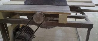
Machine based on the steering rack of a passenger car
A steering rack for a car and a drill are quite massive products, so the frame should also be massive and, preferably, with the ability to attach the machine to a workbench. All elements are welded, since connections with bolts and screws may not be sufficient.
The frame and support post are welded from channels or other suitable rolled products, about 5 mm thick. The steering rack is secured to a stand, which should be 70–80 mm longer than the rack, through the eyes of the steering column.
To make the machine more convenient to use, the drill control is placed in a separate unit.
Assembly procedure for tabletop drilling machines:
- preparation of all elements;
- attaching the stand to the frame (check verticality!);
- assembly of the movement mechanism;
- fastening the mechanism to the rack;
- fastening the drill (check verticality!).
All fastenings must be made as securely as possible. It is advisable to join one-piece steel structures by welding. When using any kind of guides, you need to make sure that there is no lateral play during movement.
Advice! To fix the part in which the hole is drilled, the machine can be equipped with a vice.
You can also find ready-made stands for drills on sale. When purchasing, you need to pay attention to the weight of the structure and the size of the working surface. Lightweight (up to 3 kg) and inexpensive (up to 1.5 thousand rubles) racks are suitable for making holes in a thin plywood sheet.
Drill device
Fantasy is an indispensable condition for any creative success, but in mechanical engineering it is useless without accurate calculations and comparison with solutions proven by experience. The history of machine tool construction goes back thousands of years - foot-operated bow lathes and drilling machines were used already at the end of the Stone Age. On the topic of this article, a proven sample is an industrial-style desktop vertical drilling machine. We will refer to it when choosing and deciding how best to make a drilling machine with our own hands: there are only a few examples of drilling machines in use that are over 100 years old, and they still maintain accuracy.
The structure of a desktop vertical drilling machine is shown in the figure:
Design of a desktop vertical drilling machine
Its main modules are a bed, a column, a console and a table for a part. The components of the main nodes are slightly highlighted in color, and their components are brighter in color. The simplest table (not counting a wooden block) is a vice. The rotary-sliding table allows, in addition to drilling, to perform some milling operations. The bed is usually tightly attached to a workbench or other reliable support.
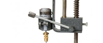
Screw clamp – clamp of the mini-drilling machine console
In operation, the console is installed in the required position in accordance with the size and configuration of the workpiece using the lifting and rotating mechanism of the slider, and is fixed. The spindle is fed into the working stroke by a separate feed mechanism. In amateur and industrial designs for home use, the lifting and turning mechanism is most often the operator’s hand, and the lock is a screw clamp of the slide, see fig. on right; According to TB, both are acceptable. But what must certainly be in the design of a drilling machine according to the requirements of the same safety regulations is a bumper device or just a bumper: if you throw the feed handle, the spindle or carriage along with it should automatically bounce up until it stops. In home drills, the chipper is most often a spring installed in a suitable place, see below.
Note: industrial production, sale and use at enterprises and workshops of individual entrepreneurs of drilling machines without a fender device are prohibited by PTB.
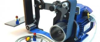
Drilling machine with washing machine motor
To make a homemade drilling machine that is ideal for a home workshop, you will need profile pipes and other available materials. First of all, it is necessary to make a base for the vertical stand of the machine - for this we weld a frame from a 60x60 mm rectangular profile.
Basic welding work
We weld a steel sheet 4–6 mm thick on top of the metal frame, which must first be cut to size so that it does not protrude beyond the edges of the profile. We clean the seams using a grinder. Next, we make a vertical stand - for this we cut a profile pipe with wall dimensions of 60x60 mm and a length of 65 cm.
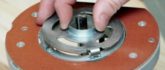
Then we weld the vertical post to the base. From a steel corner 25x25 mm you need to cut four pieces 8 cm long. Stepping back from the edges of the corners 2 cm, we drill holes - you need to cut threads in them. We put bearings on the bolts, tighten them with nuts and screw these parts into the holes in the corners.
We prepare four plates to the size of the structure, and then compress them with clamps and weld them together with the corners with bearings. Next, we weld a piece of profile pipe to the plate.
Drilling machine assembly steps
We fasten the profile pipe with the plate to the guide using bolts with hexagon heads. Before welding the spindle, you need to make a seat for it so that the joints have a small gap.
The mounting for the electric motor is very simple - anchor bolts with a ring are screwed to a 25x25 mm corner, and two bushings are welded to where the motor is directly attached. The pulley and shaft can be removed from the old grinder.
At the last stage, the lifting mechanism and handles are manufactured, which are attached to the washer by welding. All elements are painted and then assembled. The result is a very cool and inexpensive DIY drilling machine.
Rate this post
Source: https://sdelairukami.ru/sverlilnyj-stanok-s-dvigatelem-ot-stiralki/
Make or buy?
An electric drill is a ready-made drive, gear, spindle and chuck in a monoblock. Place it on the carriage of the machine and you can drill. In terms of accuracy, the solution, generally speaking, is not optimal (see below), but in many cases it is acceptable, but eliminates the need to order expensive turned parts of increased accuracy, see below. In view of this, frames for installing drills are now sold only on the street from trays; prices are affordable. When choosing one to make a drilling machine from a drill, be guided primarily by the operating mode of the equipment; The price also depends on it:
- Occasional drilling/milling for yourself with the accuracy of what you get - cast plastic bed or stamped steel. The feed mechanism is lever with a cranked lever (see below). Carriage sliding bearings (see below) are steel on steel or with nylon liners. Prices are $20-$30.
- Regular drilling for yourself or to order with ordinary machine-building precision. The materials processed are up to the hardness and toughness of ordinary structural steel. Everything is the same, but the sliding bearings are steel on steel (worse) or with bronze bushings, and the frame is cast iron or (more expensive) composite, also vibration-absorbing. Prices: $30-$40.
- Regular drilling and milling of any materials that can be tooled with periodic overloads of the tool and/or with increased accuracy - plain bearings are only bronze on steel, cast iron frame. The feed mechanism is rack and pinion (see below); vibration-absorbing console. Prices: $60-$180.
Note: as a rule, drill stands are optionally offered with a rotary-sliding table for the part, which allows for certain types of milling. Price within $20.
Choosing a bed
The stand for the drill (which sellers for some reason stubbornly call stands) must be chosen not according to - not “China”); Now the market is full of “German China”, not to mention products from post-Soviet states. The design needs to be checked.
First, samples with plastic non-nylon liners for sliding bearings are definitely rejected: runout and drill drift of more than 0.5 mm will appear already on the 10th – 20th “hole” and will further increase. The second is console play. We take it by the far end, swing it up and down and to the sides while holding the latch. There should be no noticeable “chatter” (the tactile sense of an untrained person feels a beat of 0.4-0.5 mm).
Next is an inspection of the structure, see Fig. below. For regular drilling, the one shown in pos. 1. The ideal option is at pos. 2: collet clamp of the drill, shifting the column to the side reduces the vibration of the console by an order of magnitude, and by turning it sideways by 45 degrees, you can mill the part by hand with the precision “as best you can” on a standard fixed table, removing a couple of table fasteners, because in this case, its manual displacement relative to the horizontal working axis of the console will be linear.
How to choose a bed (stand) for a drill
And here is a sample for pos. 3 do not take under any circumstances. Firstly, the collar of its column is low and its fastening is unreliable. Secondly, longitudinal grooves under the table facilitate manual milling “as it happens,” but, unlike diagonal ones, they do not dampen vibrations of the bed. Moreover, they will concentrate where shown by the arrows (the tide under the column is made too narrow) and from there they will go straight into the column and table.
Which is cheaper?
Bench Drill Press Spindle Drawings
Let’s say the price for the machine you like doesn’t suit you. Or a drill, if it’s a “crowbar” one, with an impact mechanism, that was used in work on building structures and the beating of the chuck is visible to the eye. Then the first thing we do is find out if there is a craftsman within reach who owns a lathe with high precision (no rougher than 0.02 mm). Which, by the way, is not a fact - a high-precision machine is very expensive and never pays off with the flow of regular orders. But let's say he was found. We take the drawing in Fig. on the right, we go to him and ask if he can turn it out of steel no worse than 30KhGSA, and how much he will charge for the work. “This” is the drawings of the tabletop drill spindle. The rest of its parts can be turned on a regular machine, or found in ruins at an iron market or in your trash. Most likely, it will turn out that it is cheaper to buy a bed + table, and if you estimate the costs for the rest, then perhaps a drill of increased accuracy will emerge. There are some of these on sale; they can be recognized by the absence of a striking mechanism and a collar specifically for installation in the frame: a turned steel cuff is put on it.
Materials and tools for making the machine
Before starting work, you need to think through the sequence of all technological operations in the manufacture of a homemade machine, plan the manufacturing technology, decide on future materials and tools that will be needed during the work process.
To make a machine with your own hands, you will need the following materials and components:
- Plywood 15 mm.
- Pine board, solid;
- Furniture drawer guides;
- Sleeve;
- Furniture footwear;
- Wing nut;
- Fastening: M6 bolt, self-tapping screws of various lengths.
To make a machine from a drill or screwdriver, you will need the following tool:
- Circular saw or sawing machine.
- Jigsaw.
- Angle grinder (angle grinder or simply “grinder”).
- Drill or screwdriver.
- Grinding machine.
- Various hand tools: hammer, screwdriver, clamps, wood core drill (or simply “crown”), square, marking pencil, etc.
If you do anyway
However, there may be cases when a homemade drilling machine will either be cheaper or completely free, or the best drill on the bed will not replace it. The fact is that, in addition to bending and vibration loads, torsional loads from the working tool (tool - drills, cutters) are also transmitted to the column. This is due to the difference in the lever arms from the axis of the column to the nearest and far edges of the tool; the torsional loads from a cutter gnawing the material with one edge are an order of magnitude greater than from a drill. Therefore, it is unrealistic to achieve a machining accuracy of more than 0.1 mm with a drill on a bed (see below for why), but let’s say a hole of 2.7 is needed for an M3 thread; under M2.5 – 2.2, and the processing error in this case turns out to be unacceptable. In general, making a drill with your own hands makes sense, despite the costs, if:
- You are a radio amateur and work with components with pin pitches of 2.5 and 1.25 mm (“millipedes” with a pitch of 0.625 mm are mounted only on a plane). Then you need a drilling machine for printed circuit boards with an accuracy of at least 0.05 mm;
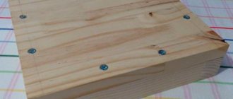
- You do other fine wood and metal work. For example, it is impossible to make a beautiful, elegant box or a reliable hiding place in the house using only hand drilling;
- You drill/mill from time to time for yourself and the accuracy will suit you, but the stash is full of all sorts of junk metal.
Note: in the latter case, you are lucky, suddenly there is an old children's bicycle lying around somewhere. Its frame tubes are of excellent steel, and the wheel hub is almost a finished spindle; The only option available to order is an adapter with a Morse taper for a tool chuck. Working thoughtfully and carefully, an old bicycle can be turned into a drill press with an accuracy of approx. 0.1 mm, or actually a free drill stand, see for example. video:
Video: DIY drill stand
Layout
But let’s say we need higher accuracy, and we need to mill the grooves without losing it. In this case, the layout of the machine becomes of paramount importance.
The best option is to locate the spindle and drive on opposite sides of the column, pos. 1 in Fig. The heavy motor in this scheme acts as a counterweight to earthquake-resistant buildings: it reflects vibration and torsional loads from the spindle in antiphase. In the region, the columns partially cancel each other out. The damping is maximum if the center of gravity of the carriage is exactly along the axis of the console, and the higher, the thinner the drill and the less pressure on it. That is, the accuracy of the machine in delicate work increases, and at the same time, it can withstand quite significant overloads without losing it.
Layout diagrams of homemade drilling machines
Note 4: it is possible to make a drill for precise work with a direct drive to the spindle and the location of it and the drive on one side of the carriage if there is a ready-made vibration-damping frame, for example. from an old microscope (under 2), etc. optical devices.
In mini machines for printed circuit boards and jewelry work, an unpleasant effect is observed: in order to obtain an accuracy above 0.05 mm, the column has to be made disproportionately thick, pos. 3. This is due to the fact that its ability to absorb vibrations and torsional loads is determined by the cross-sectional area, which decreases squarely as the size of the part decreases. For circuit boards for components with a pin pitch of 2.5 mm, as well as minor metalwork and carpentry work, an accuracy of 0.05 m is sufficient. In this case, the main influence on its deterioration is exerted by column bending loads. To fend them off, it is enough to use a double column made of a 10-14 mm bar made of ordinary structural steel, pos. 4. If the usual accuracy of 0.375 mm is sufficient, then by doubling the column, a drilling machine for occasional work can be made even from a drill and propylene water pipes, pos. 5. Its service life before loss of accuracy is small, but the material is cheap and does not require custom processing.
Innings
The design of the spindle feed mechanism (carriage in a drill machine) also plays an important role in drilling accuracy: jerks and/or uneven feed force at least increase drill runout. When drilling with a thin carbide drill, in this case, it is very likely that it will slip, break, and, as a result, irreparable damage to the labor-intensive workpiece.
In machines and stands for high-precision drills, a rack-and-pinion feed mechanism is used (on the left in the figure), ensuring its complete uniformity and, which is especially important for manual feed, exactly proportional impact of the tool stop in the hand. This requires a rack and a gear-tribe with a well-defined tooth profile - involute. Otherwise, the feed will be jerky even with absolutely smooth pressure on the handle. It is unrealistic to make a rack-and-pinion pair with identical involute teeth “on the knee”; Finding a suitable ready-made pair is unlikely, so rack-and-pinion feed mechanisms are extremely rare in homemade drills.
Types of tabletop drilling machine feed mechanisms
More often they make a simple single-lever feed mechanism, in the center in the figure, but this is far from optimal. At the beginning and at the end of the working stroke, when the smoothness of the feed and the accuracy of drilling are especially important, it does not transmit enough emphasis to the hand, and in the middle of the stroke it is excessive, which increases the likelihood of the tool getting stuck in viscous material. The feed mechanism with a cranked breaking lever on the right is free from these shortcomings; in addition, it additionally dampens console vibrations. The knee shoulder ratio is taken to be approx. 1:1.
Serving table
Drilling thin, fragile/ductile parts is more accurate, and the likelihood of the drill leaving and breaking is less if the spindle is fixed and the table with the part is fed upward towards it, therefore, in many drills for fine work, the table is equipped with a separate feed mechanism. Due to the inertia of thinking, it is often also made rack and pinion, see for example. Further. But, taking into account that the mass of the table in this case is much greater than that of the part, a table with a lever feed turns out to be no worse, but completely accessible for manufacturing at home. Its device is shown in the figure:
Table design with lever feed for a drilling machine
There is only one nuance: to prevent the clip from moving during assembly, it is tightly inserted into the through hole of the base and welded from below (from the bottom). You need to cook with an OMA-2 electrode or thinner with a direct current of 55-60 A using short, diametrically opposed clamps (“poke”). Table dimensions for printed circuit boards and jewelry work are 60-150 mm in diameter; thickness 6-12 mm. Table shank diameter 12-20 mm; length per feed stroke +(20-30) mm. It is advisable to machine the tube for the shank (wall thickness from 1.5 mm) or drill it and pass it with a reamer so that the shank moves smoothly in it without noticeable play. The short lever arm is made to be approx. equal to the diameter of the table; long - whatever you want.
Console
Let's look again at Fig. with factory frames. The designs of their consoles with half-frame carriages are similar; they are quite rational, but are designed for automated and robotic production: precision casting and then finishing on site on a CNC unit with laser measurement.
A diagram of an analogue console with an amateur-made half-frame is shown on the left in the figure:
Console design of a homemade drilling machine
The first thing that attracts attention is that you need to cut out 5 parts from a thick steel sheet, trimmed (processed with an end mill) so that the sides are even and parallel. Second, the end cuts of inserts filled with dark gray must also be smooth, clean, and parallel. Those. and here you can’t do without a milling machine. Finally, outside production conditions, it is unrealistic to perform a sliding mating between the slider and the guide carriage (shown by the arrow) with a backlash of less than 0.1 mm. Let's estimate the ratio of the lever arms - the transverse runout of the drill turns out to be more than 0.5 mm.
The design of the console of a drilling machine, which is not technologically advanced in mass production, but is adapted for production using artisanal methods, is shown on the right in Fig. (the feed mechanism and drive with bracket are not shown). Moreover, in it, the runout of the drill on inhomogeneities of the material causes the carriage on the column and the guide to skew in opposite directions, and the lateral movement of the tool does not exceed the amount of play in the sliding liners. Only one part is cut out of a thick plate - slider 4. Its precise processing is necessary only in the area of clamping the column and installing the guide, and 3 bronze bushings-liners will be precisely adjusted in place by any turner of average qualification, if you give him a column and a carriage guide (they can be machined with normal precision).
To prevent the entire assembly from welding, you need to cook it as before. case: electrode OMA-2 or thinner, direct current up to 60 A. The seams are also welded alternately with tacks: a “poke” on one, the same on the same distant one, located symmetrically. Then tack the seam closest to the first, the same on the diametrically opposite one, etc., etc., until all the seams are welded.
Note: the accuracy of a machine with the described console will be higher if it is assembled not by welding, but by screws and gluing with high-strength metal glue (cold welding). First, everything is assembled without glue, the clips are checked for parallelism and the fasteners are tightened. Then the screws are turned out one by one, glue drips into the socket and screwed back tightly. It’s a tedious task, but in this way it’s possible to get a homemade drill with a drill runout of less than 0.02 mm. Unless, of course, the spindle and chuck are centered just as well.
Errors in design
All efforts to make a drilling machine with your own hands will go down the drain if fundamental errors were made during its design. The most common of them are shown in the figure:
Typical mistakes when making a drilling machine
Pos. 1 – is this a console or what? This frame will not withstand the normal load from the tool stop for long. There is no need to talk about accuracy. Pos. 2, in addition: it is impossible to make the column of the drilling machine tubular. The pipe can withstand bending loads, but is powerless against torsional loads, and only increases vibrations.
Pos. 3 – the temptation is great to make a drill from an old photographic enlarger, especially since it is made with at least initial, but optical precision. But! The magnifier rod holder is not designed to support the tool. As a result, when drilling hardboard, the drill drift at a feed rate of 20 mm reaches 1.5 mm (!). And the bracket is made of silumin: this material does not absorb vibration, gets tired quickly, and the bracket breaks in less than the 200th hole, even when drilling printed circuit boards.
Pos. 4 – doubling the column in the transverse direction does not give anything. The resistance of the machine to loads will be no higher than on a single pin of the same diameter. Pos. 5, in addition: a rebound spring that is asymmetrical relative to the axis of the column does not dampen vibrations and torsional loads, but enhances them. Since this is the case, it was necessary to install 2 identical springs on both racks. It would be better to make a column, as shown here:
Video: do-it-yourself drilling machine from a drill
Pos. 6 – installation of the drive and spindle on one side of the column, and even asymmetrical, does not reduce, but increases vibrations, because they are transmitted to the column in phase, see above. Pos. 7 – where is the bump stop? Yes, it cannot be here, since the feed drive is screw. Using a screw, you can accurately adjust the slider (which is not here at all), which is generally not necessary on a home machine, but under no circumstances should you feed the carriage! This structure will almost throw fragments of drills and shavings, and the operator’s eyes will be in close proximity to the danger zone.
How to make a machine from a washing machine engine
Anyone may need a machine. In a professional workshop or in an ordinary utility room, such a device must be located. Let's try to make the necessary device with our own hands.
Washing machine machine
Parts for assembly
Work on the manufacture of a drilling machine using a washing machine engine will not require special design skills or talents - perseverance and ingenuity will be enough. However, you need to understand that its operation in the future will already imply knowledge of certain safety precautions, since a certain risk of injury will be present.
For manufacturing, you will need the engine itself, which will generate energy to operate the entire system, and a mechanism that includes all functional elements: drive, drill, frame, all kinds of additional electrical equipment, etc.
To correctly install the washing machine motor, in addition to the motor itself, you will need:
- V-belt;
- engine pulley;
- pulley on the door shaft;
To assemble the rest of the mechanism you need to stock up on the following parts:
- drill chuck;
- drill shaft;
- fasteners;
- bearings of several varieties: 8103 and 6003 2RS;
- staples, an angle of 50 mm and a square beam with dimensions of 30*60*30 cm made of steel;
- metal square sheet 40*40 cm.
In addition, you will need to build the turntable yourself - you will have to weld it yourself from three hairpins, soldering them to each other. You will also need a steering rack. Such a spare part, taken from a VAZ-2108, would be a good fit - fortunately, it’s easy to find them at a disassembly site, and they cost mere pennies. As a rule, a ready-made version is used as an electrical circuit - for example, TDA 1085.
Machine device
When assembling a structure, the main thing is to understand that its simplicity is the key to its reliability and the absence of unforeseen difficulties in the process. An example is the V8 steering rack, which is used as one of the main components. After all, what could be simpler than using the moving mechanism of a car for its main purpose, but in a different unit.
At the initial stage, actions are carried out in the following order:
- Creating a frame by soldering a metal sheet and a steel beam.
- The steering rack is screwed to the beam using bolts with brackets (example - in the photo below).
- The steel stud is cut into 5 pieces of equal size and welded into the shape of blades. As an analogue, you can purchase ready-made ones, the main thing is that the size is suitable.
The next stage is the manufacture of the basis of the mechanism, with the help of which it will move in place and be used for its intended purpose. How to do this:
- The corner must be cut so that the resulting parts can be used to assemble a rectangular frame to which all elements will be attached in the future.
- Bearings are put on the bolts used for fastening to give free movement to the future drilling mechanism.
- Now you need to screw the resulting frame to the movable steering rack - for this, the latter is equipped with another end of the corner with drilled holes for bolts.
- From the remaining two corner pieces, you will need to weld a square-shaped profile - a drill shaft with bearings will be placed in it, with a chuck and a pulley located on both sides, respectively. Next, you just need to screw the last part to the steering rack (example in the photo below) - and the base for the drilling machine is ready.
- A pulley is mounted on the motor shaft, and it is installed on a frame welded from corners, and then screwed from the side to the moving mechanism of the machine.
- A drive belt is stretched between the pulleys, and the motor is connected to the microcircuit board.
After this, having powered the machine with electricity, you can already test it in action. In this case, it is better to protect the microcircuit using a plastic case - to eliminate the risk of damage to the contacts and loss of power supply.
Of course, it’s easiest to start assembling if you already have at least some idea about something like this. The best memory, as we know, is visual, so the video below will help you delve into the process in more detail.
Conclusion
As is clear from the description above, you don’t need to be a genius to build such a structure.
Purchasing the parts necessary for it is unlikely to hit the wallet too hard, while the usefulness of the resulting mechanism in economic activity of any kind is very difficult to overestimate.
Of course, it is better to carry out the assembly in a specialized workshop, but in the absence of one, which most likely will be the case, you can equip an ordinary garage for these purposes - there will be plenty of space there.
The service life of a machine, i.e., its shelf life, is determined, first of all, by the frequency of operation, the materials that have to be drilled, and problems or lack thereof with power supply. As a rule, none of the above problems arise, so the mechanism lasts for many years.
Source: https://1stiralnaya.ru/sovety/stanok-iz-dvigatelya
Making a drill from a car steering rack
For many, this solution will not be obvious, but experts will immediately appreciate its simplicity and functionality. We make a drill based on the steering rack of a car. To do this, you only need the rack itself from an old decommissioned, disassembled car, or just a rack from a car that no longer exists.
You will also need fasteners and the drill itself. A steering rack drilling machine is an excellent solution for permanent work!
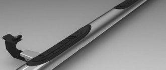
Making a ratchet from an old hand drill
The range of tool capabilities does not end there. You can also make a convenient ratchet wrench from an old and unnecessary hand drill. Moreover, it can be used as a regular wrench, that is, tightened by hand, or in tandem with a screwdriver.
To make the tool, you will need two bevel gears and a drill shaft, as well as steel tubes, plates and a welding machine. The process of making the tool is shown in detail in the video material. The result is a universal hand tool that is definitely stronger than modern ratchet wrenches.
As you can see, a hand drill is a very interesting tool from which you can make various homemade products, expanding your capabilities and also simplifying your work. If you come up with something else that can be done with a hand drill, be sure to share it, as it will help people use an outdated tool to do new things.
Common Mistakes
If mistakes are made during the manufacturing process of a home drilling machine, all the costs of money, time and other resources will be wasted. Typical errors are shown in the figure:
Each figure shows the following typical errors:
errors in the manufacturing process of a home drilling machine
- Low accuracy and weakness of the frame under the influence of standard load;
- The column should not be hollow inside, otherwise it will not withstand the bending load;
- The rod will not support the tool stop.
- There is no point in doubling the column transversely. This will not increase stability.
- The bump stop (in this case, the spring), due to its disproportionate size, does not dampen loads and vibrations, but rather enhances them.
- An asymmetrical arrangement of the drive and spindle on one side of the column will only increase vibrations.
- The main mistake is the lack of a bump stop as such. It must not be used as it is hazardous to health.
Many owners who independently engage in construction and construction have an electric drill. However, one such tool may not be enough for operations requiring high precision, right angle drilling or complex tasks. To achieve these goals, drilling machines are created - installations that can be made at home from scrap materials and household appliances. There is nothing complicated about how to make a drilling machine from a drill.
Additional materials (drawings):
how to make a drilling machine from a drill with your own hands drawings
how to make a drilling machine from a drill with your own hands drawings
how to make a drilling machine from a drill with your own hands drawings
Summary
Article Name Do-it-yourself drilling machine from a drill - detailed instructions, drawings
Description It is better to make or buy ➜— Do-it-yourself drilling machine ➜— Common mistakes ➜— Drawings ➜— Location of the main structural elements.
Author
Publisher Name
Wikipedia of construction tools
Publisher Logo
What materials are needed to create a mini drill with your own hands?
- Of course, an electric motor . The power supply is preferably no more than 12 volts: at least for safety reasons.
- Power supply , if possible with a voltage regulator (to change the number of shaft revolutions).
- Housing (in the most primitive designs you can do without it).
- And the second most important part (after the motor) is the drill chuck .
Everything except the electric motor can be made independently. Although, the cost of the remaining components is so meager that you can limit yourself to only assembling power tools from ready-made components.
Let's look at a few tried and tested options.