Without a compressor you can't go anywhere. Buying a new one in a store is expensive. And buying a productive one of at least 260 liters like the ZILovsky is even more expensive, but the weak one didn’t give up for nothing. You have to get out and follow the path that most people follow - build a homemade one.
The biggest difficulty facing the construction of a homemade compressor based on the ZIL is the cooling and lubrication system, which works in close conjunction with the lubrication and cooling system of the ZIL internal combustion engine. The whole root of evil is hidden in these two systems.
At first, something like this thought was spinning in my head: buy a power steering pump from some old bucket at a disassembly, weld a radiator from a profile pipe, or buy one and use the radiator to circulate power steering oil along the lubrication circuit and at the same time along the cooling circuit.
Do it yourself or buy a ready-made device
Today's market for pressure boosting and air injection devices is replete with variety. Screw, piston and other types of compressors are produced for different purposes. Those who have chosen a ready-made device should choose the type of mechanism with the required technical characteristics and at the optimal price.
Of the variety of products offered, of course, it is better to choose products from well-known brands. Their main disadvantage is their high cost. Large amounts of money will only pay off if you engage in professional car repairs.
If you purchase a cheap device from an unknown brand, you need to be prepared for unpleasant surprises. Inexpensive products are often made of low-quality material, the engine fails, and warranty repairs last for several months.
A unit made by hand from Zilovsky (ZIL 130) is considered by many craftsmen to be more reliable. According to numerous reviews, such a device has good performance, durability, and wear resistance.
In addition, a repair kit for the Zilov compressor can be purchased at any auto parts store. A self-made, high-quality device that works for a long time and works properly will delight its owner and become the envy of many car enthusiasts.
After studying the instructions for making a device with your own hands from a ZIL 130 compressor, you can come to a conclusion: buy a pig in a poke or make the device yourself.
Plunger repair
If a plunger breaks, repairing the compressor should begin by unscrewing the front crankcase. Next, unscrew the protective cover
After this, it is important to remove the two plates that are clamped with rings. If they do not loosen, you can knock them out a little with a hammer
The next step is to inspect the oil seal. As a rule, a large amount of dirt accumulates on it.
If the supercharger is working properly, then everything inside the block should be clean. In this case, the valves are inspected separately. To remove the plunger, it is recommended to use a large wrench. Doing this yourself is problematic due to the fact that you need to constantly hold the piston. In this case, it is more advisable to ask a friend for help.
You can effectively and quickly clean any part or structure surface for further repair or use using sandblasting. But this device requires a source of compressed air with the necessary pressure and performance. A self-made compressor for sandblasting will save you from purchasing expensive and not always sufficiently reliable equipment.
Step-by-step instructions for making a paint compressor from Zilovsky
To create a device that pumps air, compressors are used:
- ZIL 130;
- ZIL 157;
- MAZ;
- KamAZ;
- GAS;
- MTZ.
The KamAZ device has good performance, is durable and reliable, but requires serious modification, while GAZ and MTZ are ineffective. Therefore, many people choose a Zilov unit to make a device that pumps air with their own hands.
Let's look at an example of such an assembly. Let's take as a basis the ZIL 130 compressor, a 50-liter propane cylinder. For a 220-volt network, you need a 2-3 kilowatt motor; when using 3 phases, the power may be less. The frame is made of angle steel; bolts, screws, sealant, and clamps are required for fastening.
- First of all, we make a pallet. For this you need a metal sheet 5 mm thick. To avoid oil leaks at the junction of the sump with the compressor crankcase, a paronite gasket and sealant treatment are used.
- To prevent the device from jamming during operation due to poor lubrication, it is necessary to fine-tune the components. To do this, you need to remove the head, take out the connecting rods and drill them together with the liners. The depth of the holes should be 3 mm, diameter - 10 mm. This is enough to lubricate the bearings. During operation of the device, an oil mist is formed, which lubricates the cylinders.
- The next step is to make two threaded holes in the crankcase. We screw in the fitting for filling and draining oil here.
- The system must be connected to the painting area with a special tube. The air coming out of the device is very hot, so copper products are used for this purpose.
- If the compressor performance is not enough to operate the device’s spray gun, you can connect additional receivers. To control the pressure, a pressure gauge is installed on the receiver. If the pressure is insufficient and unstable, the paint layer on the car body will lie unevenly.
- An overload valve can be installed in the receiver, which will protect the device in case of excessive pressure increase.
- Many craftsmen also install a dehumidifier. For these purposes, a special dryer (alcohol) from a KamAZ vehicle is used, which is located between the compressor and the receiver. Alcohol and antifreeze are used as working fluids.
For a car enthusiast who has little experience in welding and plumbing, making an air injection device based on a ZIL 130 compressor with his own hands will not be difficult if you follow our recommendations.
A practical option
The design based on the compressor from MAZ, ZIL 130 - 157 has proven itself as a reliable, efficient device. The unit from these cars will require minimal do-it-yourself modifications. From MTZ, GAZ is ineffective, but from KamAZ it needs major improvements. The receiver is installed based on the needs for sandblasting - a 50 liter gas cylinder or a ready-made one from a KamAZ vehicle and a smaller one from a ZIL, which already have the necessary holes.
The approximate layout of a self-made device and the pneumatic connection diagram for the compressor are as follows. The receiver, in a horizontal position, is installed on supports with wheels. A compressor without a bottom cover is installed on a piece of channel 200–250 mm wide through a paronite gasket. At the opposite end of the channel, through milled grooves, an electric motor is mounted on feet. The grooves are necessary for tensioning the belt, which is selected with a small cross-section so that power losses on the drive are minimal. The channel is attached to the top of the receiver, the wiring from the compressor to the receiver is connected from above and from the end, a pressure control gauge is installed, an overload valve and an outlet fitting with a valve are mounted from the end.
The electric motor is selected depending on the needs. For a 220 V network, the minimum required power of a three-phase electric motor is 1.5 kW, speed – 1420 rpm. The required gear ratio between the motor shaft and the compressor pulley in this case is 1: 3. At higher powers, the ratio is reduced - productivity increases. For a 220 V power supply, 2.2 kW is optimal. By using 380V (3 phase), the power can be reduced.
The outer diameter of pulleys for automobile units is approximately 210 mm. In the case of using a 1.1 kW motor with an 80 mm pulley, the gear ratio is 210/80 = 2.6. The electric motor will operate at maximum power at a pressure of 8 atm. A capacity of 260 l/min (maximum) is obtained at 2500 rpm of the compressor shaft. By changing the ratio, you can reach 3200 rpm - the maximum speed of the unit on the ZIL 130.
Breather
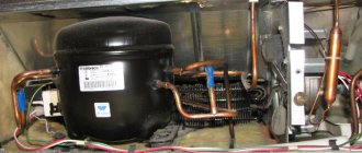
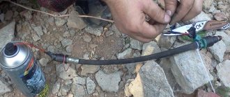
In the ZIL engine, the compressor crankcase is directly connected to the engine crankcase, and the engine crankcase, in turn, is connected to the atmosphere through a breather. In our case, the compressor crankcase cannot be connected to the atmosphere in any way and during compressor operation it squeezes out the crankshaft oil seals.
I solved the problem by installing a homemade breather. I drilled a hole in the place where, in my opinion, it would be the least likely to be bombarded with oil. I cut a thread in the hole and screwed a fitting into it, put a hose on the fitting and threw it over my head downwards. Although unpresentable, excess pressure began to be released and the seals are now in place.
Crankshaft device
The crankshaft in this case is connected to the crankcase.
The outlet channel is used with a small diameter. The cylinders on the ZIL-130 compressor are installed on the sides. It should also be noted that there are two linings on the bottom side of the modification. The shaft is fixed on the clamp. The fact that the guides of this compressor are installed on the left side deserves additional attention. When the shaft is shorted, experts recommend inspecting the entire supercharger. The crankcase is also checked, since it usually collects all the debris from recycled oil. To ensure proper operation of the system, the pressure inside the unit is tested. You also need to immediately clean all the channels from the crankcase. This can be done using a regular cleaning rod. The seat is pre-lubricated. If the shaft is deformed, it must be replaced immediately. Prices for ZIL-130 spare parts are quite reasonable. The tip of the part is welded on manually.
Compressor test
When testing a compressor on a bench, the compressor shaft rotation speed should be 1800...2000 min. The compressor must be supplied with I20A oil, GOST 20799-75
under pressure 0.25...0‚30 MPa (2.5...3.0 kgf/cm2), oil temperature 35...50 °C.
It is recommended to run the compressor at idle speed for five minutes. During the break-in process, you should make sure that there are no oil leaks, overheating of the bearings and that there is no knocking of the pistons, pins and exhaust valves.
At 800...2000 min of the compressor crankshaft and communication of the cylinder 3 with the environment through a calibrated hole with a diameter of 1.6 mm and a length of 3 mm, the pressure in the container after 50 should reach a value of at least 0.6 MPa (6 kgf/cm2).
The compressor is tested for oil throughput at 800...2000 min and an oil pressure of 0.25...0‚30 MPa (2.5...3.0 kgf/ohm2). In this case, the amount of oil flowing through the drain hole of the compressor crankcase cover (with the calibration hole open) should be no more than 220 g per minute.
The operation of the unloading system is checked by supplying compressed air under a pressure of no more than 0.5 MPa (5 kgf/cm2) into the channel of the unloading chamber, while the plungers 4 (see Fig. 8 - 11) must rise and fully open the inlet valves 8.
Test stand diagram
When the pressure is removed, the plungers must clearly return to their original position under the action of the return spring. Perform this operation at least three times.
Check the exhaust valves for leaks by connecting the compressor head to cylinder 3 (Fig. 8-13) with a capacity of 1 liter, as indicated in the diagram, at a pressure of 0.60...0‚65 MPa (6.0...6.5 kgf/cm2) . In this case, the pressure drop in the cylinder should not be more than 0.04 MPa (0.4 kgf/cm2) per minute.
Checking the tightness of connections is carried out with a soap solution at an air back pressure of 0.65 MPa (6.5 kgf/cm2).
Before installing a pressure regulator on a compressor, it must be checked, tested and adjusted to operate within the specified air pressure limits.
Plunger mechanism
The plunger mechanism of this compressor is used with a bearing row. Experts say that the part can withstand heavy loads at high speeds
However, it is important to note that the inlet valve needs frequent cleaning. In this case, the channel becomes clogged quite often
To check it, the crankcase is unscrewed. You will also have to remove the cover. An adjusting screw is used to adjust the plunger. When the cover comes out, you can install a large screw. In this case, it is necessary to select the appropriate protective ring. To solve problems with abrasion of the lining, special means are used to seal the block. Some experts recommend periodically cleaning the tubules.
Motorists may also encounter problems with the plunger base. It is a regular plate, which is fixed on a thread. If there is a lot of shaking, the connection breaks down quite quickly. As a result, the plate begins to wobble. To correct this situation, it is recommended to first remove the cover
After this, it is important to immediately clean the outlet. The screw unscrews very slowly
In this case, you need to monitor the position of the bearing row.
Installing the compressor on the engine
Install the washers, then manually install the compressor onto the engine, directing the slots of the cover-bracket to the cylinder head studs. Tighten the compressor mounting nuts by hand. Place the drive belt on the pulley, adjust the belt tension and tighten the nuts.
When installing the compressor, it is necessary to ensure a gap of at least 5 mm between the radiator outlet hose and the compressor air pipe. The specified clearance is achieved by turning the radiator outlet hose. The clearance is necessary to prevent chafing of the hose by the compressor pipe.
Replacing the sealing rings of the compressor unloader plungers on a car
Checking the condition of the sealing rings of the plungers of the unloading Device and replacing them can be done without removing the compressor head. In this case, the following order must be observed:
- Start the engine and increase the pressure in the pneumatic system until the pressure regulator operates.
2. Stop the engine
- Remove the rubber hose connecting the engine air filter to the compressor. If the tightness of the unloading device is broken in the air supply pipe to the compressor, a characteristic noise of the air being passed through is heard, and a slight drop in pressure is noted on the pressure gauge of the pneumatic system.
- Reduce the air pressure in the pneumatic system to the lower control limit, while the plungers must be lowered.
- Remove the air supply pipe, take out the spring and rocker arm. Then lift the rod socket and remove it together with the rod, then remove the plunger from the socket with a wire hook, inserting it into a hole with a diameter of 2.5 mm in the end of the plunger or supplying compressed air to the horizontal channel of the cylinder block unloader.
- Replace worn rubber O-rings on the plungers. Before installation, plungers with sealing rings should be lubricated with engine oil.
Device
Do-it-yourself sandblasting machine: a master class on how to make an effective device with your own hands
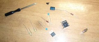
The compressor is a two-cylinder piston-type device. Its operating principle is to pump air through the movement of pistons. The compressor device consists of:
- wire housing with channels;
- oil seal;
- springs;
- seal.
The pistons are made of aluminum and equipped with pins that are secured with retaining rings. Through the intake valves, the air in the engine air filter enters the compressor cylinders. It is compressed by pistons and enters the pneumatic system. Then it passes through the discharge valves, which are located in the cylinder head.
Cooling system
The engine has a closed liquid cooling system. It consists of: radiator, thermostat, pump, temperature sensor, compressor and pipe. It works on the principle of forced circulation of cooling. If the fluid in the system overheats, it is necessary to open the radiator cap. When it is opened, a stream of hot water is ejected from the neck
Therefore this must be done carefully
Lubrication system
The lubrication system is combined. The lubricant comes from the lubrication unit of the motor system and cools with the help of coolant.
Lubrication system
A drill is a useful tool! We drill through holes in the connecting rod according to the principle: the more holes the better, the more holes the better!
We assemble the compressor into a heap, adapt some fitting to the drain from the pan, put a hose on the fitting and, in order to maintain the oil level at the proper level, connect the hose to some kind of tank. I adapted the tank from a construction hydraulic level.
What do we get as a result?
As a result, we get a device practically for free that is only suitable for inflating tires or for other work that is not demanding on air quality.
Such a compressor is absolutely not suitable for painting and also for pneumatic tools. The compressor turns out to be bad: it heats up after a few minutes and starts throwing condensate into the system. The oil also throws out with terrible force and you have to constantly top it up. In general, it’s still bullshit.
I have been using this compressor for several years now, and all these years I have understood that such things need to be done initially in a normal way with a normal lubrication system and normal cooling. In all these years he has never satisfied me in this form and never will. But if you don’t have money, you’ll have to put up with these disadvantages.
How to make a paint compressor based on ZIL 130 with your own hands
- Do it yourself or buy a ready-made device
- Step-by-step instructions for manufacturing equipment for supplying air from a Zilovsky unit
- Useful video
The best basis for creating a paint compressor with your own hands is ZIL 130, the compressor of which is structurally most suitable for this.
For body painting, the use of a compressor is important, as it improves the quality and strength of the applied layer and increases productivity. In addition, it can be used to inflate tires and supply air to pneumatic tools.
Due to the considerable cost of the compressor, purchasing a device for a “one-time” painting of your car is not practical, and not everyone can afford it. Home craftsmen can make such a device with their own hands.
Do it yourself or buy a ready-made device
Today's market for pressure boosting and air injection devices is replete with variety. Screw, piston and other types of compressors are produced for different purposes. Those who have chosen a ready-made device should choose the type of mechanism with the required technical characteristics and at the optimal price.
Of the variety of products offered, of course, it is better to choose products from well-known brands. Their main disadvantage is their high cost. Large amounts of money will only pay off if you engage in professional car repairs.
If you purchase a cheap device from an unknown brand, you need to be prepared for unpleasant surprises. Inexpensive products are often made of low-quality material, the engine fails, and warranty repairs last for several months.
A unit made by hand from Zilovsky (ZIL 130) is considered by many craftsmen to be more reliable. According to numerous reviews, such a device has good performance, durability, and wear resistance.
Interesting! In addition, a repair kit for the Zilov compressor can be purchased at any auto parts store.
A self-made, high-quality device that works for a long time and works properly will delight its owner and become the envy of many car enthusiasts.
After studying the instructions for making a device with your own hands from a ZIL 130 compressor, you can come to a conclusion: buy a pig in a poke or make the device yourself.
Recommendations from experts
- If a compressor is made from Zilovsky, the tools will need to be selected very carefully. You will need to have a drill, a welding machine, a set of wrenches and much more. Situations may also arise when some types of work are easier to do in the factory or using special machines.
- To create shock absorbers when fixing all units to a frame or supporting frame, it is best to use rubber gaskets or inserts. However, it is worth remembering that with intensive use they wear out quickly and you should always have spare ones.
- When purchasing a compressor, you must be very careful, since the appearance of the product does not indicate the condition of its internal components and assemblies. It is simply not possible to check the product on the spot, which means that such a purchase should only be made from trusted sellers.
- If the problem with overheating of the compressor is not solved, then it must be operated in a gentle mode. This way it will last much longer, although this may cause some inconvenience during operation. That is why the unit is selected for specific needs.
- You can install a pressure gauge with special contacts on the product, which are connected to the electrical engine starting circuit. This automates the operation of the device and will also reduce the likelihood of rapid overheating.
- The electrical circuit for connecting the compressor to the electrical circuit directly depends on the type of engine selected. At the same time, you should not come up with workarounds for starting the primary winding so as not to lose power. This will affect the operation of the product if there is residual pressure in the receiver, even with a check valve and a fairly powerful engine.
Step-by-step instructions for manufacturing equipment for supplying air from a Zilovsky unit
To create a device that pumps air, compressors are used:
- ZIL 130;
- ZIL 157;
- MAZ;
- KamAZ;
- GAS;
- MTZ.
The KamAZ device has good performance, is durable and reliable, but requires serious modification, while GAZ and MTZ are ineffective. Therefore, many people choose a Zilov unit to make a device that pumps air with their own hands.
Let's look at an example of such an assembly. Let's take as a basis the ZIL 130 compressor, a 50-liter propane cylinder.
The frame is made of angle steel; bolts, screws, sealant, and clamps are required for fastening.
- First of all, we make a pallet. For this you need a metal sheet 5 mm thick. To avoid oil leaks at the junction of the sump with the compressor crankcase, a paronite gasket and sealant treatment are used.
- To prevent the device from jamming during operation due to poor lubrication, it is necessary to fine-tune the components. To do this, you need to remove the head, take out the connecting rods and drill them together with the liners. The depth of the holes should be 3 mm, diameter - 10 mm. This is enough to lubricate the bearings. During operation of the device, an oil mist is formed, which lubricates the cylinders.
- The next step is to make two threaded holes in the crankcase. We screw in the fitting for filling and draining oil here.
- The system must be connected to the painting area with a special tube. The air coming out of the device is very hot, so copper products are used for this purpose.
- If the compressor performance is not enough to operate the device’s spray gun, you can connect additional receivers. To control the pressure, a pressure gauge is installed on the receiver. If the pressure is insufficient and unstable, the paint layer on the car body will lie unevenly.
- An overload valve can be installed in the receiver, which will protect the device in case of excessive pressure increase.
- Many craftsmen also install a dehumidifier. For these purposes, a special dryer (alcohol) from a KamAZ vehicle is used, which is located between the compressor and the receiver. Alcohol and antifreeze are used as working fluids.
Useful! For a car enthusiast who has little experience in welding and plumbing, making an air injection device based on a ZIL 130 compressor with his own hands will not be difficult if you follow our recommendations.
Unit repair
Separately, it is worth mentioning how such a unit is repaired if any breakdowns occur in it. Breakdowns may be indicated by noise or knocking that occurs during operation of the compressor, or by oil penetrating into the air cylinder being filled:
- The appearance of cracks or chips on the crankcase itself. To eliminate the damage, a complete replacement of the crankcase is required when the damage is located on the walls. Or they are welded in a situation where they are on the mounting flange and also have small dimensions.
- In order to check the tightness of the cylinder itself, it should be placed in a water bath, and then filled with air under high pressure. The appearance of bubbles will indicate the presence of damage. To eliminate this problem, the container is bored and then honed to the required size.
- When ball bearings become unusable, they are pressed and then replaced with new ones.
- If the crank pin wear exceeds 0.05 mm, a complete replacement of the crankshaft is required.
- In order to repair the upper head of the connecting rod, it is necessary to press in the repair sleeve, where a hole is made in advance. Its diameter should be 14.019 mm.
The permissible repair size of the piston depends on the number stamped on the bottom of the product. Usually this is +04 or +08.
Compressor circuit
Step-by-step instructions for making a paint compressor from Zilovsky
To create a device that pumps air, compressors are used:
- ZIL 130;
- ZIL 157;
- MAZ;
- KamAZ;
- GAS;
- MTZ.
The KamAZ device has good performance, is durable and reliable, but requires serious modification, while GAZ and MTZ are ineffective. Therefore, many people choose a Zilov unit to make a device that pumps air with their own hands.
Let's look at an example of such an assembly. Let's take as a basis the ZIL 130 compressor, a 50-liter propane cylinder. For a 220-volt network, you need a 2-3 kilowatt motor; when using 3 phases, the power may be less. The frame is made of angle steel; bolts, screws, sealant, and clamps are required for fastening.
First of all, we make a pallet. For this you need a metal sheet 5 mm thick. To avoid oil leaks at the junction of the sump with the compressor crankcase, a paronite gasket and sealant treatment are used. To prevent the device from jamming during operation due to poor lubrication, it is necessary to fine-tune the components. To do this, you need to remove the head, take out the connecting rods and drill them together with the liners. The depth of the holes should be 3 mm, diameter - 10 mm. This is enough to lubricate the bearings. During operation of the device, an oil mist is formed, which lubricates the cylinders. The next step is to make two threaded holes in the crankcase. We screw in the fitting for filling and draining oil here. The system must be connected to the painting area with a special tube. The air coming out of the device is very hot, so copper products are used for this purpose. If the compressor performance is not enough to operate the device’s spray gun, you can connect additional receivers. To control the pressure, a pressure gauge is installed on the receiver. If the pressure is insufficient and unstable, the paint layer on the car body will lie unevenly. An overload valve can be installed in the receiver, which will protect the device in case of excessive pressure increase. Many craftsmen also install a dehumidifier. For these purposes, a special dryer (alcohol) from a KamAZ vehicle is used, which is located between the compressor and the receiver. Alcohol and antifreeze are used as working fluids.
Receiver
They usually try to make a typical iron-based compressor from the ZIL 130 compact and mobile. Therefore, using large and voluminous receivers simply does not make sense. Also, you should not purchase these elements of the unit separately, since you can always create them yourself. You can use almost any metal container for this. In this case, it is best to use gas cylinders or old fire extinguishers.
It should be noted right away that further refinement of the receiver will be required. You will need to install a pressure gauge and pressure regulator on it. Usually a separate unit with a gearbox is purchased, which is installed at the entrance to the container. It is also very important to install a back pressure valve. It is adjusted to the optimal operating mode of the future product with a certain margin of 10-15%.
Here are its brief characteristics
- two-piston;
- piston diameter 60mm;
- volume 12 cm cube;
- weight – 14kg;
Here's what we need to make a compressor for painting a car:
- compressor from ZIL;
- empty propane tank;
- 2-3 kW motor;
- metal corner;
- hoses, clamps, sealant and all sorts of small things;
- at least familiarity with the basics of metalworking, welding and turning.
The compressor from the ZIL car does not have a bottom, so we make it from a steel sheet 5 mm thick. We seal the structure with 2 mm thick paronite and sealant on both sides to prevent oil leakage.
The most difficult stage in our proposal is the modification of the compressor lubrication system. To do this, you need to disassemble it, take out the connecting rods, but do not forget to mark where they stood. We drill the connecting rods together with the liner: three holes of 3 mm each and countersink them with a diameter of 10 mm. Everything is shown in the picture.
Zil 130
—
Repair
of brake mechanism parts
Zil
-
130
.
... Cracks on the cooling jacket of the compressor
... beyond
the repair dimensions
,
compressor
... https://interdalnoboy.com/pro-zil-130/remont-i-ekspluataciya/remont-detaley-mehanizmov-tormozov.html
We carry out this entire procedure so that our compressor does not seize: in our case, lubricant is not force-fed, as in a car, but is scattered throughout the crankcase and lubricates the crankshaft through these holes.
- Drain plug of any size;
- Oil drain fitting if the pressure is excessive;
- Plug for filling hole of any size;
- Adapter for connecting the air system and the painting area, 3/8 thread. The tube is made of copper, because the place where the compressor connects to the head gets very hot - the hoses will burst and the plastic will melt.
Compressor ZIL 130
, started about him and his drive (+
...
Nov 27, 2011 ...
Inserts for
ZIL
, as well as for KamAZ, are available in three
sizes
: standard and two
repair ones
03 and 06. The same goes for rings: standard 60.0
repair
60.4...https://www.chipmaker.ru/topic/72219/page__st__60
Drill a hole 3 10 mm below the center of the crankshaft.
We install fitting 2 into this hole; it is advisable to take the tube from the carburetor, since it is petrol and oil resistant. A couple more tips: we weld the propane cylinder only by filling it completely with water, to do this we unscrew the bronze valve; If there is not enough air volume for painting, install additional receivers.
Found a mistake? Select the text with the mouse and press Ctrl+Enter