What is better - homemade or purchased?
In total, there are several main differences between them:
- The design of the factory compressor contains an electric motor that transmits torque to the working chamber through a belt drive. As for the homemade compressor, it consists of a housing and the engine itself, without belts.
- The factory version already has automatic pressure relief systems, inlet and outlet filters, pressure meters, etc. installed. In a compressor from a refrigerator, you will have to install the control equipment yourself, taking into account all the features.
- Despite the fact that most factory compressors are equipped with automatic systems, some budget models do not have this feature. In other words, these units will have to be turned off independently, noting the time on the clock. Homemade compressors are mainly equipped with a protective relay that turns off the engine if there is a risk of overheating.
- Some factory models may not have any lubrication at all. Of course, they are small, but they lack various exhausts. This circumstance is very important, especially if the spray gun behaves rather capriciously, not tolerating various impurities. As for homemade compressors, there is plenty of oil.
- The main feature of a homemade compressor is that it works very quietly, especially if you put all the tubes on it correctly, maintaining a tight seal. As for factory compressors, they are noisier, so their use is only possible outside the home.
- The cost of manufacturing a homemade compressor is very low, because the main components are taken from old equipment, and the control equipment will cost a maximum of 1000 rubles.
- It is impossible to make any technical changes to the factory compressor. In other words, if the unit is not powerful enough, then it can only be used as a tire inflator, nothing more. Homemade options are good because you can add some parts to them, for example, a large receiver, thanks to which you can significantly increase the power of the device.
As practice shows, a homemade compressor for painting a car breaks down much less often than its foreign and domestic factory counterparts. On the Internet you can find many instructions on how to build compressors with your own hands. So let's discuss several options that can help in this matter.
Electric turbine for a car. Is it possible? Is it possible to do it yourself? Only the real truth
If we jump ahead a little on the topic, it turns out that now all turbocharged engines use mechanical air compressors; this approach has many advantages and many disadvantages. But recently, many companies began to think about electric turbines that will not use exhaust gases from the car, and also will not have mechanical connections and drives, and the air will be pumped by an electric motor that will be “powered” from the on-board system...
Not a bad idea! After all, you can avoid many of the disadvantages of mechanical systems, especially turbines that run on exhaust gases, such as:
2) Turbine cooling
3) Engine oil lubrication
5) Well, and of course a resource
If we draw the line, we can understand that mechanical systems are far from ideal. Of course, compressors that operate from drives will be more reliable. However, they also have disadvantages; this is the same drive that uses a regular belt for operation, which wears out over time.
In general, the developers thought and realized that mechanics can be replaced with electrics! Or is it not possible?
Schemes for making a homemade compressor
Here are several options for device assembly schemes - choose which one is best suited for your purposes:
Compressor assembly parts
- pressure switch;
- pressure gauge;
- gearbox with oil and water separator;
- oil/water separator filter;
- adapters;
- crosspiece;
- fitting and nut;
- coupling;
- nipple;
- a tube;
- car clamps;
- receiver;
- nuts, studs, washers;
- furniture wheels;
- automobile oil;
- toggle switch;
- plug and cord;
- fuel filter;
- plywood panels (chipboard);
- refrigerator compressor;
- oil and petrol resistant hose, screws, Epoxylin, sealant, paint, fum tape, rust remover and other small things.
I checked several different control valves in my versions. After several attempts, I ordered a RUCK14IAMSV check valve, it does not buzz and can be perfect for building a compressor from refrigeration units. You also need to buy a safety valve (MINI SVM14-12). Take a tank from a 16 kg powder fire extinguisher. The pressure in the tank is 9.5 bar, the shelf life is 2 months.
Important: pay attention to what kind of oil you pour in - synthetic oil does not combine very well with regular oil, so you don’t need to pour in just anything.
- An oil separator must be installed between the compressor and the tank.
- Oil should be added through the third solder tube.
- It is best to solder the connector and screw it in with a screw or metal plug.
- Install a dehydrator, it will also capture the oil.
Due to the sudden failure of the refrigerator, I became the owner of an efficient 110 W unit. Of course it can be converted into a compressor. There is a car airbrush, which was previously used with a 12-watt compressor, as well as with a high-power compressor. These devices are noisy and short-lived. So I had to make a homemade one.
A few words about Chinese electric turbines
Literally 2 years ago, the “auto Internet” simply exploded with electric turbines from China. A small “thingy” was offered, which was installed in the gap in the air intake hose, which supposedly pumped air with pressure into the engine, a promised increase in power by as much as 15%! The engine itself was an incomprehensible cooler, neither electricity consumption, nor speed, nor pumped air - there were no indicators. If you even disassemble it visually, it becomes clear that this is a cooler similar to advanced computer coolers, so what can it increase? NOTHING! So we just don’t buy - it’s a SCAM.
Now, of course, other electric turbines are starting to appear on the same Chinese sites, many are even made in the shape of a snail - ala a mechanical compressor. But again, there are no indicators of pressure, consumption, or air pumping. Think before you buy. Let's watch an educational video.
Compressor assembly instructions
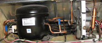
It is important to dismantle the compressor correctly to avoid damaging it. First, using wire cutters, cut through the tubes coming out of the engine leading to the radiator grille. Next, the wires from the relay are cut, but their length should remain approximately 20 cm. Before unscrewing the compressor, you need to make a mark on the relay cover.
Once the compressor blower circuit from the refrigerator is broken, the spindle will be exposed to the atmosphere, which will lead to a loss of its properties. If the factory oil in the supercharger is not replaced, its pistons will quickly wear out, causing the engine to fail. Therefore, it is recommended to first replace it with a semi-synthetic motor one. like from a car.
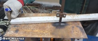
In addition to the outlet and inlet tubes, the compressor from a conventional refrigerator is equipped with a third tube with a sealed end. In order to use it in the future to paint a car, it is necessary to remove the clogged part. To do this, using a hacksaw for metal, you should make a neat cut around the tube, but without sawing all the way through, and then break off the cut piece. It is important that metal shavings do not get inside.
The remaining pipe must be flared and the old oil drained, then semi-synthetic oil must be poured into it in the same quantity. After which the pipe is sealed with a screw wrapped in fum tape.
The fire extinguisher housing is perfect for the receiver. It is important that it is cast, seamless and has a volume of 10 liters or more. Before using it, you need to inspect the inside of the fire extinguisher for corrosion. A flashlight is used for inspection. If corrosion is still present, it must be removed using a special liquid.
Semi-professional air blower
To create a semi-professional compressed air installation, you will need a larger number of components and tools. In particular, instead of a rubber bladder, it is advisable to use a propane cylinder. In addition to this you will need:
- Fittings for fastening metal hoses.
- Metal plates, the width of which should be 30-40 mm and the thickness 3-4 mm.
- Two wheels with a platform for attaching it to the receiver.
- Compressor.
- Hardware.
- Fittings for pressure adjustment.
- Welding machine – inverter.
- Screwdriver.
- Metal cutters.
- Grinder with abrasive wheels.
- Metal brush;
- Adjustable wrenches, pliers.
Working mechanism
To assemble a semi-professional air blower, you can use a compressor from a non-working refrigerator made in the USSR. These refrigerators are superior to their imported counterparts in that they are capable of producing higher air pressure.
Air container
Propane cylinders and old fire extinguishers can be used as containers for compressed air. This is due to the fact that these containers are able to withstand quite high pressure and have a large margin of safety.
Stages of assembly work
Making a compressor from a refrigerator means following a simple sequence of steps:
- Take pliers, a 12mm spanner, 2 screwdrivers - one for plus and one for minus. At the bottom of the rear panel, use pliers to cut through the tubes connecting the compressor to the cooling system. Unscrew the start relay, having previously marked the top and bottom sides on it. Disconnect the relay from the plug. We take all the fasteners with us.
- Checking functionality: reconnect the relay, provide air access to the compressor through the tubes, connect to the network. If everything is done correctly, the device works. Air will flow into one tube and out of the other. Label these tubes.
- Attach the compressor with self-tapping screws to a wooden board.
- We take an old fire extinguisher, 1 hose 600 mm long, 2 others - 100 mm, fuel filter, clamps, pressure gauge, sealant. We already have a drill, a screwdriver, and pliers.
- If there is no fire extinguisher, then we will make a plastic container. To do this, you need to take a container with a volume of more than 3 liters. Make 2 holes. Insert the inlet tube into 1 hole at a distance of 2 cm from the bottom of the container. We lower the outlet pipeline 10 cm deep. It is impossible to install a pressure gauge on a plastic tank.
- If there is an iron tank, then the tubes can be fixed by welding. We install a pressure gauge on the iron receiver. We fasten the receiver and compressor together.
- Place a filter on a 10 cm long hose and attach the free end of the tube to the inlet of the constructed apparatus. We use another hose to connect the receiver inlet to the compressor outlet. We fix the joining places with clamps. A diesel filter is attached to the last hose, and its free end is inserted into the outlet of the receiver. If necessary, equipment can be attached to the remaining end of the tube to make airbrushing and painting available.
Second version of step-by-step instructions:
- We drill a special hole for the adapter that needs to be secured. You can choose different methods, for example, the most affordable is cold welding (using Epoxylin).
- Carefully clean the bottom of the receiver from contaminants - plaque and rust. This is necessary so that Epoxylin adheres well to the surface for strong bonding. And, of course, so that the paint does not become dirty and does not form into lumps with debris. This can be achieved by sanding the bottom of the fire extinguisher to a metallic shine using rotating and circular movements using sandpaper.
- We secure the adapter by clamping it from the front side with a nut, and give the Epoxylin time to harden according to the instructions.
- Let's move on to the base for the compressor, for which you need to acquire three wooden boards or a piece of plywood measuring 30 by 30 cm. For the convenience of further moving our device, you can screw mobile furniture wheels to the base. We do not specifically describe the dimensions of the holes and other details, since this will all be purely individual, as it depends on the selected material, type of compressor, and so on.
- We drill holes for the compressor and studs and mount them. The studs are secured with nuts and washers. We put a car filter with a special paper core on the inhalation of the compressor. This will help prevent dust and other small contaminants from getting inside the compressor.
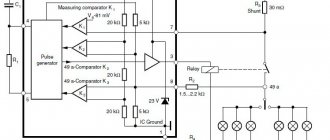
- Next we'll deal with the electrical work. To make our homemade compressor for painting a car convenient to use, we equip it with a pressure switch (for example, PM5 or RDM5), as well as a shutdown switch. The first device, a pressure switch, is necessary for us to turn off the compressor during the process of pumping air into the receiver, when the pressure reaches the permissible maximum, and vice versa, to turn it on when the pressure drops below the permissible minimum. You can set the values of the maximum and minimum pressures directly on the relay using springs, with the large spring responsible for the minimum pressure (and the corresponding activation of the compressor), and the small one for the difference between the maximum and minimum pressure values.
- Take a closer look and you will see 2 contacts on the relay, designed specifically for connecting it to the network. Since such relays were originally used in the water supply system, we will slightly change its purpose and connection features. Our task is to connect the first contact to the network, and the second to the compressor.
- We place the general shutdown switch on the gap between the pressure switch and the 220V network. This will help de-energize the entire installation so that you don’t have to constantly run around to turn it on and off.
- We paint the receiver and begin final assembly.
- Screw the nut with the fitting onto the oil-moisture separator filter.
- We take the hose and put one end of it on the fitting, and with the other we pull it onto the compressor tube and clamp it all with clamps. To do this, we take a reinforced, oil-resistant hose. Each threaded connection should be sealed with fum tape.
- We screw the filter to the bottom of the receiver and treat the silicone connection with sealant.
- We screw on the cast iron lid, but pre-treat its threaded connection with the same sealant. To improve sealing, you can place a rubber gasket under the lid.
- You need to screw a tube onto the lid, the thread of which should be a quarter of an inch, and screw the cross onto it.
Is it possible to make an electric version with your own hands?
Hypothetically, it is possible, and many people install this on their car. Personally, I also thought about installing it on my car, but the price stopped me.
You need to solve a number of points:
1) Definitely installing a powerful generator, which is already expensive for a foreign car.
2) A powerful and compact electric motor, preferably brushless, it produces high speeds with optimal energy consumption. Personally, I have seen these for compact models, but with a power of 0.5 kW and above they are also not cheap.
3) Impeller and housing. You also need to make it yourself or buy it for maximum air injection. Also not an easy task.
4) And of course, a stabilizer or inverters to power the electric motor.
The tasks are not simple, some foreign cars do not have powerful generators, so it is very difficult to do!
But many craftsmen install it on their cars in the garage; an increase in power can actually be achieved up to 20 - 30%.
Moreover, many people install an additional air consumption sensor in the pipe in front of the turbine; it “sees” the pumped volume and automatically regulates a larger fuel supply (supplies values to the ECU) to enrich the fuel mixture. So the firmware may not be needed.
To sum it up, it turns out that an electric turbine on a car is possible, I’ll even say that you can do it yourself, but not everything is so simple and often “the game is not worth the candle.” After all, you need to remake not only the car’s electrical system, but also the fuel supply system; you may need ECU firmware.
Did you like the article? Subscribe to the channel to stay up to date with the most interesting materials
Installation of device parts
For ease of storage and movement, it is best to arrange all compressor parts compactly on one base. We will use a wooden board as a base, on which we securely mount the engine - supercharger and fire extinguisher housing.
We fix the compressor motor using threaded rods threaded into pre-drilled holes and nuts with washers. We place the receiver vertically, using three sheets of plywood to secure it, in one of which we cut a hole for the cylinder.
We attach the other two using self-tapping screws to the supporting board and glue them to the sheet holding the receiver. Under the bottom of the receiver, at the base, we hollow out a recess of appropriate size. For maneuverability, we screw wheels made from furniture fittings to our base. Next we perform the following operations:
We protect our system from dust and coarse particles, for which we use a coarse fuel filter for gasoline engines as an air intake. For this purpose, we use a rubber hose that tightly presses the filter fitting and the inlet tube of the supercharger. There is low pressure at the compressor inlet and reinforcement of contact using automotive clamps is not required. Thus, we made an inlet filter for the compressor with our own hands.
An oil separator should be installed at the compressor outlet; it will not allow liquid particles to pass through. We use a diesel engine power system filter as this protection element. We connect it to the supercharger using an oil-resistant hose. Since the pressure at the outlet of the compressor is increased, here and everywhere else, to strengthen the contact, we use automotive clamps with fasteners tightened with a screw.
We connect the oil-moisture separating filter to the input of the gearbox. We need a reducer to decouple the pressure of the receiver and the outlet of the supercharger. We screw its high-pressure outlet into the water crosspiece on the left or right.
We screw a pressure gauge from the opposite entrance of the quad, using it we will control the pressure of compressed air in the cylinder. We screw the adjusting relay on top of the cross. We seal all connections with fum tape and sealant.
The relay will allow you to set a wide range of pressure levels in the receiver, promptly interrupting the supercharger power supply circuit. You can choose PM5 or RDM5 as the actuator. These devices will turn on the compressor if the compressed air pressure in the receiver drops below the set level, and turn off when the specified range is exceeded. The required pressure is adjusted on the relay using two springs. The large spring sets the minimum pressure level, and the small one regulates the upper limit, setting the compressor shutdown limit. RDM5 and PM5 were originally produced for use in the water supply network and are electrically passive, that is, they are ordinary switches with two contacts. We connect one contact to the zero of the 220 V network, and the second to the supercharger.
We connect the phase wire of the network through a toggle switch to the second network input of the compressor. The introduction of a toggle switch into the electrical circuit allows you to quickly disconnect the system from power without having to run to the outlet every time. We solder all electrical connections and carefully insulate them.
Compressor testing and adjustment
Now all that remains is to paint the entire compressor and move on to field testing.
After assembling the structure, you should check its functionality. We connect a spray gun or a tire inflation gun to the compressor output. After that, with the toggle switch off, plug in the plug into the network. We set the control relay to minimum pressure and then apply power to the supercharger. The pressure created in the receiver is controlled using a pressure gauge. After making sure that when a certain level is reached, the relay turns off the engine, we check the tightness of the air ducts and connections. This is easy to do with a soap solution.
After making sure that the compressed air does not leave the system, we bleed it from the receiver chamber. As soon as the pressure in the cylinder drops below the set mark, the relay should operate and start the compressor. If everything is functioning properly, you can try painting some unnecessary part. Preliminary work to prepare the surface for applying enamel is not required here - it is important for us to develop skills and determine what pressure will be required to paint the product. We experimentally determine the value in atmospheres at which the excess pressure is enough to paint the entire part in a uniform layer with a minimum number of blower activations.
Disadvantages of the electric option
Many of my readers think that making such a system is very simple, you need to take some kind of cooler and insert it into the air intake pipe and that’s happiness! Such “miracle coolers” are usually sold in Chinese online stores; we’ll talk about these types below.
However, guys, not everything is so simple here. In normal (idling) mode, a naturally aspirated 1.6-liter engine consumes approximately 300 - 400 liters of air per hour of operation. And at high speeds, say 4000 - 5000, we multiply this figure by 4 - 5, that is, 1200 - 1600 liters. Just imagine this volume! If you calculate the minute consumption 300/60 = 5 liters per minute, or 20 at high speeds.
Adjustment and testing
The main test of a homemade compressor is to determine the possibility of effectively regulating the pressure that is created in the assembled system. The easiest way to do this is to test paint a surface. In this case, the following is done sequentially:
- Set the relay to 4…5 atmospheres.
- Connect the compressor to the network.
- The stability of the parameter is monitored using a pressure gauge. If the relay is operational, then if the pressure is exceeded, it will turn off the compressor; otherwise, open the relief valve and immediately turn off the unit.
- Check the system for spontaneous bleeding of the energy carrier, for which you can use a regular soap solution.
- When the pressure drops to a level below the minimum permissible, the relay should automatically turn on the compressor.
- After painting any surface, it is necessary to check the quality of the paint applied to it - during an external inspection, no traces of moisture, foreign particles and dirt should be detected. If such defects do occur, you should additionally check the operation of the output filter - oil and water separator.
Conclusions and recommendations for maintenance
The operation of the assembled unit will be long and reliable if routine maintenance is carried out periodically. It comes down to replacing inlet filters, periodically purging all air ducts, and also changing the oil in the compressor.
It is undesirable to load the compressor by more than 75% of power. But it is quite difficult to understand where the line is that cannot be crossed, to predict what pressure the compressor will show. It depends on when the refrigerator was released and what brand it is. On older models this figure will be better. Then, for comfortable, high-quality work, you only need to replace the consumable filters.
Principle of structure
It should be noted that now some German manufacturers have such superchargers in their engines. And they are installed, as you understand, in the air intake system. Mercedes, BMW and AUDI were the first to use such superchargers.
The principle here is simple - a powerful “fan” is installed, which creates a pressure of approximately 0.5 atmospheres (and possibly more). Powered by the vehicle's electrical system, it pumps additional oxygen into the engine to increase power. With fuel supply settings, you can achieve a significant increase - about 20 - 30%.
The electric turbine should also be adjusted to certain speeds, for example, at idle it should work slower, and at high speeds, correspondingly faster. It turns out to be almost an ideal system! But what’s the catch, where are the downsides? And you know, they exist.