Flashing LEDs are often used in various signal circuits. Light emitting diodes (LEDs) of various colors have been on sale for quite a long time, which blink periodically when connected to a power source. No additional parts are needed to make them blink. A miniature integrated circuit that controls its operation is mounted inside such an LED. However, for a novice radio amateur it is much more interesting to make a flashing LED with your own hands, and at the same time study the principle of operation of an electronic circuit, in particular flashers, and master the skills of working with a soldering iron.
[contents]
Testing flashing RGB LEDs
A computer power supply is almost an ideal option for testing SMD0603 LEDs.
In this case, you just need to install a resistive divider. To do this, according to the diagram from the technical documentation, the resistance of pn junctions in the forward direction is assessed using a tester.
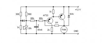
Direct measurement is not possible here. Instead, you should assemble the circuit shown in the figure. Here are the considerations we proceeded from, and what is shown in the picture:
- The microcircuit is given along with the numbers of the legs according to the technical data.
- Power is supplied to the cathode because the polarity of the voltage is negative. 3.3 V is just enough to open the pn junctions.
- A variable resistor does not need a very large value.
In our picture it is installed with a maximum limit of 680 Ohms. This is exactly the position he should be in initially.
Usually the on-pn junction resistance is not very high, but we need a significant margin so that the diodes do not burn out (we remember that their maximum forward voltage is 3 V).
Also taken into account is the fact that at low voltage the resistance of each LED will be about 700 Ohms. When connected in parallel, the total resistance is found according to the formula shown in the figure below
Substituting 700 there as all three input parameters, we get 233 Ohms. This will be the resistance of our LEDs at the moment when they are just starting to open (at least we think so).
The bottom line is that we need to control the mode with a tester (see figure above).
To do this, we constantly measure the voltage on the LED chip, while simultaneously reducing the resistance value until the potential difference rises to 2.5 V. Further increasing the voltage is simply dangerous, perhaps many will stop even at 2.2 V.
Then, from the proportion, we find the required resistance of the LED chip: (3.3 – 2.5)/2.5 = R AC / R total, where R AC is the resistance of the variable resistor at the moment when the voltage on the tester display reaches 2.5 V. R total = 3.125 R per.
The +3.3 V wire on the computer power supply has orange insulation, and we take the circuit ground from black.
Please note that this module does not need to be turned on without load. It would be ideal to connect a DVD drive or some other device to one of the connectors
You can also simply remove the side cover and remove the necessary contacts from there.
The connection of LEDs is illustrated by the diagram. Many will ask – what next? Have you measured the resistance for parallel connection of LEDs and stopped?
Let us explain: in working condition, if you need to turn on several LEDs, we will make a similar adjustment. As a result, the supply voltage on the chip should be 2.5 V.
Please note that the LEDs are flashing so readings may not be entirely accurate.
In this case, the maximum reading should not exceed 2.5 V. Well, and, of course, it will be clear that the circuit is working, because the LEDs will start blinking.
In order for only some of them to manifest themselves in this regard, it is necessary to remove food from unnecessary ones. It is also possible to assemble a debugging circuit with three variable resistors - one in a branch of each color.
Thus, we now know how to make a flashing LED backlight with our own hands.
And now many will ask whether it is possible to vary the response time.
We believe that containers should still be used inside. Perhaps these are even the own capacitances of the pn junctions of the LEDs.
But in any case, by connecting a variable capacitor in parallel with the circuit to the input, you can try to change something.
The value must be very small and measured in pF. There simply cannot be large capacities in such a small chip.
We also assume that a resistor connected in parallel to the microcircuit (see the dotted line in the diagram above) and placed on the ground will form a more accurate divider. In this case, stability will increase.
Then you need to take more significant values, but do not forget that this will significantly limit the current flowing through the LEDs. In fact, you need to think through this issue according to the existing situation.
We receive ultra-long waves on the phone using the dendrofecal method
Hello. Not long ago I created a post on Pikabu where I asked for advice on an amplifier circuit for ADV. If anyone is interested, here it is. Well, as usual, I received a bunch of different recommendations, ranging from “nothing will work out for you, do something else” and ending with advice to buy an SDR whistle and not waste your time. That is, they didn’t really advise anything on the topic.
Well, okay, in general, I would be surprised if someone specifically answered the question asked, so I decided to do everything myself.
First of all, guided by my meager knowledge, and expanding it along the way, if you can call it that, design, I put together a circuit on an operational amplifier, like this:
The scheme fully complies with the most stringent requirements of the design pattern called “I made it out of what I had.” I didn’t buy a single part for this device; everything was soldered from some old printers, radio tape recorders, power supplies and other things that were lying around in the corner of the room. This explains the choice of an operational amplifier, which I initially wanted to buy some more suitable one, but in the end I stuck on what I found, because, to be honest, I didn’t really believe that this Frankenstein would work. The nominal values (and most, so to speak, circuit design solutions) were selected according to the principle “it seems to work in LTSpice.”
Now is the time to tell you what, in my opinion, at least, is happening here.
First of all, I tried to determine the characteristics of the microphone input of the mobile phone, and by measuring with a multimeter I found out that the signal input of the mobile phone without load holds 2.5 V, and if you load it with a resistor, the voltage drops approximately as if there was a 2.3 kOhm resistor (R4). There should also be a capacitor there, but since I have absolutely no idea how to measure its parameters, I decided to just forget about its existence. I didn’t bother with a low-pass filter at the output, since I decided that it was still included in the circuitry of the mobile itself.
That's the whole device. By the way, the chip used has 2 op amps and I decided not to use the second one, and not knowing what to do with it, I decided to just short all 3 of its pins, hoping that this would reduce the noise.
Well, now it’s time for photos.
This is the antenna. Compared to everything else, it even looks good. I even polished the wood with sandpaper to prevent splinters.
And here is an example of the spectra that can be seen with this gadget:
I also have several recordings of signals, and I can talk about what kind of signals are here, but I think that this can be left for later if someone is interested. Actually, if this post gets at least a few dozen upvotes, then I’ll make a post about it.
Source
How to make an LED flasher with your own hands
There are many schemes that can be used to make an LED blink. Flashing devices can be made either from individual radio components or based on various microcircuits. First, we will look at the multivibrator flasher circuit using two transistors. The most common parts are suitable for its assembly. They can be purchased at a radio parts store or “obtained” from obsolete televisions, radios and other radio equipment. Also in many online stores you can buy kits of parts for assembling similar circuits of LED flashers.
The figure shows a multivibrator flasher circuit consisting of only nine parts. To assemble it you will need:
- two resistors of 6.8 – 15 kOhm;
- two resistors with a resistance of 470 - 680 Ohms;
- two low-power transistors with an npn structure, for example KT315 B;
- two electrolytic capacitors with a capacity of 47–100 μF
- one low-power LED of any color, for example red.
It is not necessary that paired parts, for example resistors R2 and R3, have the same value. A small spread in values has virtually no effect on the operation of the multivibrator. Also, this LED flasher circuit is not critical to the supply voltage. It works confidently in the voltage range from 3 to 12 volts.
The multivibrator flasher circuit works as follows. At the moment of supplying power to the circuit, one of the transistors will always be open a little more than the other. The reason could be, for example, a slightly higher current transfer coefficient. Let transistor T2 initially open more. Then the charging current of capacitor C1 will flow through its base and resistor R1. Transistor T2 will be in the open state and its collector current will flow through R4. There will be a low voltage on the positive plate of capacitor C2, connected to the collector T2, and it will not charge. As C1 charges, the base current T2 will decrease and the collector voltage will increase. At some point, this voltage will become such that the charging current of capacitor C2 will flow and transistor T3 will begin to open. C1 will begin to discharge through transistor T3 and resistor R2. The voltage drop across R2 will reliably close T2. At this time, current will flow through the open transistor T3 and resistor R1 and LED1 will light up. In the future, charge-discharge cycles of capacitors will be repeated alternately.
If you look at the oscillograms on the collectors of the transistors, they will look like rectangular pulses.
When the width (duration) of rectangular pulses is equal to the distance between them, then the signal is said to have a meander shape. By taking oscillograms from the collectors of both transistors at the same time, you can see that they are always in antiphase. The duration of the pulses and the time between their repetitions directly depend on the products R2C2 and R3C1. By changing the ratio of products, you can change the duration and frequency of LED flashes.
To assemble the blinking LED circuit, you will need a soldering iron, solder and flux. As a flux, you can use rosin or liquid soldering flux, sold in stores. Before assembling the structure, it is necessary to thoroughly clean and tin the terminals of the radio components. The terminals of the transistors and the LED must be connected in accordance with their purpose. It is also necessary to observe the polarity of connection of electrolytic capacitors. The markings and pin assignments of KT315 transistors are shown in the photo.
The easiest way to determine the cathode of an LED is by holding the device up to the light. The cathode is an electrode with a larger area. The negative terminal of the “electrolyte” is usually marked with a white stripe on the body of the device.
Depending on the tasks that the radio amateur sets for himself, the flasher circuit can be assembled “on a canopy” by connecting the terminals of the radio components to each other using pieces of thin wire. In this case, you may end up with a design similar to the one shown in the photo below.
Assembling a flasher “on the knee”
If you need to assemble a flasher for subsequent use, the installation can be done on a piece of hard cardboard or a printed circuit board can be made from PCB.
Do-it-yourself car special signal.
Any motorist knows that the use of special devices.
purpose (for example, special signals such as SGU, strobe lights, etc.) is illegal and if stopped by the police, you can be fined a tidy sum, plus confiscation of prohibited devices. Therefore, the article has been prepared for informational purposes - please pay attention to this fact. So, what is the difference between a strobe and a flasher? in theory, nothing, only the type of blinking of light-emitting diodes (or light bulbs). The flasher can be assembled in 5 minutes using a conventional multivibrator, but it will be a simple flasher, and not a strobe light, which are installed on government cars. services But for the viewer's information, a strobe is simply a device that produces bright flashes of light, so that a simple flasher can also be called a strobe.
How to assemble a strobe light, the operating principle of which is similar to the flashing lights that are on police cars? A simple multivibrator is not enough here, although our design in terms of complexity is not much different from a conventional multivibrator.
First we need a single-channel pulse generator, it can be anything, it can be based on a multivibrator or, even simpler, based on the legendary 555 timer
The timer is connected as a low-frequency generator of rectangular pulses; the frequency of these pulses can be adjusted with a variable resistor.
The output pulses from the microcircuit are sent to the input of the divider counter. And then the “reading” process begins. The counter outputs switch alternately, when one of the outputs is open, all others are closed. Device diagram.
The outputs of the counter microcircuit are matched by diodes. The three outputs are connected as one, this is done in order to get a triple flash sequence for each LED. Since it is planned to connect powerful LEDs, the output was amplified with an additional transistor (in the case of each output).
Thus, we can connect even quite powerful loads, for example, incandescent lamps (12 Volts), but taking into account the fact that the main power will be dissipated on transistors and the latter will overheat quite strongly, so select transistors with a current of 10 Amperes or more and install them on the heat sink.
The diodes are the most common - 1n4148 low-power silicon rectifier diodes. The circuit works simply - the timer generates low-frequency pulses that are sent to the counter input. Each pulse will sequentially open and close the outputs from the counter, thus producing blinks, and diode isolation is made in order to obtain several blinks of one LED. For example, one of the LEDs will blink three times, then go out, then the same thing happens with the second.
The second circuit works on exactly the same principle, only here the LEDs are connected to all outputs of the microcircuit. This way we get a creeping line effect.
LEDs are the most common (just not the assembly), but if desired, you can control high-power loads by adding output transistors as an amplifying element, exactly as was done in the first design; below is a running line diagram.
The PCB for the first circuit is available for download here. Good luck!
Source
Simple circuits of flashing lights based on flashing LEDs for DIY assembly
It is recommended to start discovering the world of radio electronics, full of mysteries, without specialized education, by assembling simple electronic circuits. The level of satisfaction will be higher if the positive result is accompanied by a pleasant visual effect. The ideal option is circuits with one or two flashing LEDs in the load. Below is information that will help in implementing the simplest DIY schemes.
Ready-made flashing LEDs and circuits using them
Among the variety of ready-made flashing LEDs, the most common are products in a 5 mm housing. In addition to ready-made single-color flashing LEDs, there are two-terminal versions with two or three crystals of different colors. They have a built-in generator in the same housing with the crystals, which operates at a certain frequency. It issues single alternating pulses to each crystal according to a given program.
The flickering speed (frequency) depends on the set program. When two crystals glow simultaneously, the flashing LED produces an intermediate color. The second most popular are flashing light-emitting diodes controlled by current (potential level). That is, to make a LED of this type blink, you need to change the power supply at the corresponding pins.
For example, the emission color of a two-color red-green LED with two terminals depends on the direction of current flow.
It’s quite easy to make a flasher based on a ready-made flashing LED. To do this, you will need a CR2032 or CR2025 battery and a 150–240 Ohm resistor, which should be soldered to any pin. Observing the polarity of the LED, the contacts are connected to the battery. The LED flasher is ready, you can enjoy the visual effect. If you use a Krona battery, based on Ohm's law, you should select a resistor of higher resistance.
Conventional LEDs and flasher systems based on them
A novice radio amateur can assemble a flasher using a simple one-color light-emitting diode, having a minimum set of radio elements. To do this, we will consider several practical schemes, characterized by a minimum set of radio components used, simplicity, durability and reliability.
The first circuit consists of a low-power transistor Q1 (KT315, KT3102 or a similar imported analogue), a 16V polar capacitor C1 with a capacity of 470 μF, a resistor R1 of 820-1000 ohms and an LED L1 like AL307. The entire circuit is powered by a 12V voltage source.
The above circuit works on the principle of avalanche breakdown, so the base of the transistor remains “hanging in the air”, and a positive potential is applied to the emitter. When turned on, the capacitor is charged to approximately 10V, after which the transistor opens for a moment and releases the accumulated energy to the load, which manifests itself in the form of LED blinking. The disadvantage of the circuit is the need for a 12V voltage source.
The second circuit is assembled on the principle of a transistor multivibrator and is considered more reliable. To implement it you will need:
- two KT3102 transistors (or their equivalent);
- two 16V polar capacitors with a capacity of 10 µF;
- two resistors (R1 and R4) of 300 Ohms each to limit the load current;
- two resistors (R2 and R3) of 27 kOhm each to set the base current of the transistor;
- two LEDs of any color.
Simple LED flasher
There are simpler LED flasher circuits. One of these is shown in the next photo.
Circuit of the simplest flasher
If you look closely at this LED flasher, you can see that the transistor in the flasher circuit is turned on “wrongly”. First, the emitter and collector are connected incorrectly. Secondly, the base “hangs in the air.” However, the LED flasher circuit is quite working. The fact is that in it KT315 works as a dinistor. When the threshold value of the reverse voltage is reached, a breakdown of the semiconductor structures occurs and the transistor opens. The voltage across the transistor increases as the capacitor charges. After the transistor opens, the capacitor discharges to the LED. Since the LED flasher circuit uses a non-standard transistor connection, it may require the selection of a resistor or capacitor during setup.
After you make a simple flashing light with your own hands, you can move on to more complex flashing devices, for example, creating color music using LEDs.
Calculation of the limiting resistor
Looking at the current-voltage characteristic of the LED, it becomes clear how important it is not to make a mistake when calculating the limiting resistor
- U – supply voltage, V;
- ULED – forward voltage drop across the LED (nameplate value), V;
- I – rated current (certificate value), A.
The result obtained should be rounded up to the nearest value from the E24 series, and then calculate the power that the resistor will have to dissipate:
R – resistance of the resistor accepted for installation, Ohm.
More detailed information about calculations with practical examples can be found in the article on calculating a resistor for an LED. And those who do not want to dive into the nuances can quickly calculate the resistor parameters using an online calculator.
Necessary materials and radio components
To assemble an LED flasher with your own hands, powered by a 12 V power source, you will need the following:
- soldering iron;
- rosin;
- solder;
- 1 kOhm resistor;
- capacitor with a capacity of 470-1000 μF at 16 V;
- transistor KT315 or its more modern analogue;
- classic LED;
- simple wire;
- 12V power supply;
- matchbox (optional).
The last component acts as a housing, although the circuit can be assembled without it. Alternatively, a circuit board can be used. The mounted mounting described below is recommended for beginner radio amateurs. This assembly method allows you to quickly navigate the circuit and do everything right the first time.
Ready flashing LEDs
Flashing LEDs from various manufacturers are essentially functionally complete circuits, ready for use in various fields. In terms of external parameters, they are not much different from standard ice devices. However, their design includes a generator-type circuit and its accompanying elements.
Among the main advantages of ready-made flashing LEDs are:
- Compact, robust housing, all components in one housing.
- Large range of supply voltage.
- Multi-color design, wide variety of shade switching rhythms.
- Economical.
Usage patterns
The simplest version of the circuit of LED-based flashers produced today, which can be manufactured by radio amateurs on their own, includes:
- Low power transistor.
- Polar type capacitor 16 volts and 470 microfarads.
- Resistor.
- Ice element.
When the charge accumulates, an avalanche-like breakdown occurs with the opening of the transistor module and the glow of the diode. This type of device is often used in Christmas tree garland. The disadvantage of the circuit is the need to use a special power source.
How to make a garland of LEDs
To make a garland that periodically blinks with a given rhythm, you will need the following components and a set of tools:
- LEDs 20 mAh.
- Wiring with a cross-sectional area of 0.5-0.25 mm2.
- 6 volt transformer.
- 100 ohm resistor.
- Soldering station with a small section tip, solder, rosin.
- Knife with a sharp blade.
- Silicone based sealant.
- Felt pen.
Assembly algorithm:
- Determine exactly the spaces between the flashing elements.
- Prepare the wire and mark the LED marks with a felt-tip pen.
- At the marks, make cuts of the insulation with a sharp knife.
- Next, apply rosin and solder to the bare areas.
- Solder the diode electrodes to these places.
- Apply silicone sealant to exposed areas to provide electrical insulation.
Upon completion, connect the power supply and a regular resistor. The device is connected to the network and checked for functionality.
Advice! When making garlands, it must be taken into account that the exclusively sequential nature of the connection of LEDs in the circuit will provide their characteristic blinking effect.
Making your own flashing LED
Many devices are complemented by flashing LEDs, providing the necessary signals or simple illumination.
Features of LEDs
Before making an original flashing LED, you need to know some things about these devices.
The light emitted depends on a number of indicators; The efficiency may vary. Moreover, the weakest ones are blue; As for semiconductor elements, the efficiency of light-emitting diodes (LEDs) is quite low. In most cases it does not exceed 45 percent; Along with their low efficiency, LEDs are distinguished by their excellent efficiency in converting electricity into light energy; For every watt of electricity there are a number of photons that are approximately 6-7 times higher than an incandescent coil under similar consumer conditions; Such capabilities of LEDs explain the popularity of creating flashing lamps based on LEDs; LEDs require a low enough voltage for the circuit to work; To achieve the flashing effect, passive and key elements should be selected accordingly
Then the circuit will be able to produce blinking of the required shape - duty cycle, repetition rate or amplitude.
To create a flashing device with your own hands, you can use the Arduino platform. Arduino is a hardware computing platform. What’s most interesting is that Arduino is intended for amateur use and allows you to create all kinds of circuits.
Supply voltages for LEDs
To create a red, blue, yellow or any other LED or a full-fledged LED strip, doing this by connecting to a 220 Volt network is not the best solution.
In practice, similar circuits exist via a 220-volt power supply, but it is extremely difficult to achieve the blinking effect on your own.
To save on electricity bills, our readers recommend the Electricity Saving Box. Monthly payments will be 30-50% less than they were before using the saver. It removes the reactive component from the network, resulting in a reduction in load and, as a consequence, current consumption. Electrical appliances consume less electricity and costs are reduced.
loading…
It is much more correct when the circuit uses a more suitable supply voltage.
- 5 Volts. You can find this voltage in phone chargers and in many modern gadgets. The output current here is small, but usually not required. An additional 5 Volts can be found on the computer power supply buses. In this situation you will not be current limited. The power wire will be red and the ground wire will be black.
- 7-9 Volts. This voltage is most often found on walkie-talkies. Each company produces its own radios with its own nuances, so it is problematic to give specific recommendations. But since walkie-talkies often fall into disrepair, there is no problem getting a free charger.
- 12 Volt. 12 Volts is the standard voltage indicator for the microelectronics segment. 12 Volts are found everywhere. They are necessarily present in the same computer units. Here the insulation is the blue wire, not the red wire. 12 Volt is considered the optimal solution, so we recommend that you stick with it.
- 3.3 V. Many may say that this rating is too low, and therefore will not be particularly popular. This is partly a fair statement. But the exception is the situation where the SMD0603 RGB LED comes into play. Just keep in mind that if the forward voltage drops more than 3 V, problems may arise.
Making RGB blink
This circuit is the most interesting because it allows the use of the specified SMD LEDs.
- To connect SMD 0603, the ideal voltage source is not a battery, but a power supply from your computer. At the very least, you can test the circuit with it;
- You will need to install a resistor divider;
- To do this yourself, you will need a diagram and technical documentation. They will allow you to estimate the resistance of pn junctions in the forward direction using a tester;
- Direct measurement is not allowed here;
- Instead, a diagram is assembled.
Operating principle
An LED with flashing light emission is a standard LED crystal, the electrical power circuit of which includes a capacitance and a resistor that determine the operating mode. Externally, it is no different from ordinary analogues. In this case, the mechanism of its operation at the level of processes occurring in the electrical circuit comes down to the following:
- When current is applied to resistor R, charge and voltage accumulate in capacitor C.
- When its potential reaches 12 volts, a breakdown is formed at the pn boundary in the transistor. This increases conductivity, which initiates the production of light flux by the ice crystal.
- When the voltage drops, the transistor becomes off again and the process begins again.
All modules of such a circuit operate at the same frequency.
What is needed for production
You can buy a ready-made LED, which will start blinking when the supply voltage is applied. In such a device, in addition to the usual pn junction, there is a built-in electronic circuit made according to the following principle:
The basis of the device is a master oscillator. It produces pulses with a relatively high frequency - several kilohertz or tens of kilohertz. The operating frequency is determined by the parameters of the RC chain. Capacitance and resistance are constructive - they are the elements of the LED device. In this way, it is not possible to obtain a larger capacity without significantly increasing the dimensions of the device. Therefore, the RC product is small, and operation at high frequencies is a necessary measure. At a frequency of several kilohertz, the human eye does not distinguish the blinking of the LED, and perceives it as a constant glow, so an additional element is introduced - a frequency divider. By sequential division it reduces the frequency to several hertz (depending on the supply voltage). In terms of weight and size, such a solution is more advantageous than using a capacitor with a large capacity. The lowest supply voltage for a finished flashing LED is about 3.5 volts.
Design and principle of operation
The flasher consists of the following elements:
- power supply;
- resistance;
- capacitor;
- transistor;
- Light-emitting diode.
The scheme works on a very simple principle. In the first phase of the cycle, the transistor is “closed”, that is, it does not pass current from the power source. Accordingly, the LED does not light up. The capacitor is located in the circuit before the closed transistor, therefore it accumulates electrical energy. This happens until the voltage at its terminals reaches a value sufficient to ensure the so-called avalanche breakdown. In the second phase of the cycle, the energy accumulated in the capacitor “breaks through” the transistor, and current passes through the LED. It flashes for a short time and then goes out again as the transistor turns off again. Then the flasher operates in cyclic mode and all processes are repeated.
Schematic diagram
If the only place of possible power supply is the electrical network, then you can connect the flashing LED according to the very well-proven circuit shown in the figure. Excess voltage drops across resistors R1-R3. There are three resistors of 75 kOhm, and not one of 220 kOhm, because it is advisable to make the line longer to ensure that breakdown is avoided. Diode VD1 serves as a rectifier. Capacitor C1 is storage. Now the most interesting thing is that the circuit contains a zener diode VD1. In principle, if the HL1 LED were not blinking, there would be no need for this zener diode, as well as for resistor R4.
But NI is a flashing LED. Therefore, at those moments in time when it goes out, its resistance increases greatly and, accordingly, the voltage dropping across it also increases. If there is no zener diode VD1, the forward voltage on the NI at the moment of its extinguishing will reach 300V and maybe even more. Which will lead to its failure. There is also a zener diode here that will limit the voltage on the LED at those moments when it is turned off.
The stabilization voltage of the zener diode does not necessarily have to be 12V. The zener diode can be of any voltage that the LED can normally withstand in the off state. But not lower than its direct voltage in the burning state. That is, somewhere from 3V to 30V. Almost any zener diode for any voltage within these limits. Accordingly, capacitor C1 must be at a voltage not lower than the voltage of the zener diode.
Resistor R4 is needed in order to limit the discharge current of the capacitor through the LED at the moment of its ignition. In principle, you can do without it, but there is a high probability that the LED will not last long. So R4 is here just in case. R4 is especially relevant when using a zener diode for voltage at the upper limit (up to 30V). Because the higher this voltage, the greater the current surge will be at the moment the LED lights up.
LED operating principle
Before connecting the LED, you need to know a minimum of theory. In the region of the pn junction, due to the existence of hole and electronic conductivity, a zone is formed with energy levels that are non-standard for the thickness of the main crystal.
When charge carriers recombine, energy is released, and if its value is equal to a quantum of light, then the junction of the two materials begins to radiate. The hue depends on certain quantities, and the relationship is as follows:
E = hc / λ, where h = 6.6 x 10⁻³⁴ is Planck’s constant, c = 3 x 10⁸ is the speed of light, and the Greek letter lambda denotes wavelength (m)
From this statement it follows that a diode can be created where the difference in energy levels is E.
This will be what you are looking for. This is how LEDs are made. And depending on the difference in levels, the color can be blue, red, green, etc.
Moreover, not all LEDs have the same efficiency. The weakest are the blue ones, which historically were one of the last to appear.The efficiency of LEDs is relatively low (for semiconductor technology) and rarely reaches even 45%.
But with all this, the specific conversion of electrical energy into useful light energy is simply amazing.
Each watt of energy can produce 6-7 times more photons than an incandescent filament under the same consumption conditions. This explains why LEDs have a strong position in lighting technology today.
It is for this same reason that creating a flasher based on these semiconductor elements is incomparably simpler. Relatively low voltages are enough for the circuit to start working.
Everything else comes down to choosing the right key and passive elements to create a sawtooth or pulse voltage of the desired shape:
Amplitude. Duty factor. Repetition frequency.
How to do it? Obviously, connecting an LED to a 220V network will not be the best idea.
There are similar circuits, but making them blink is quite difficult, because the element base for this has not yet been created.
Typically LEDs operate from much lower supply voltages. Of these, the most accessible are:
+5 V voltage is present in chargers for telephone batteries, as well as iPads and other gadgets.
True, the output current in this case is small, but in most cases this is not necessary. In addition, +5 V can be found on one of the power supply buses of a personal computer.
In this case, there will be no problems with current limitation. The wire in this case is red, and look for the ground on black.
Voltage from +7 to +9 V is often found on chargers of hand-held radio stations, commonly called walkie-talkies.
There are a great many companies, and each has its own standards
In our opinion, the LED connection circuit will work best from +12 V.
This is a standard voltage in microelectronics and can be found in many places. The computer unit also contains a voltage of -12 V. The core insulation is blue, and the wire itself is left for compatibility with older drives.
In our case, it may be needed if the elemental base for supplying +12 V is not at hand. Then it will be enough to find complementary transistors and turn them on instead of the original ones. The ratings of the passive elements remain the same. The LED itself is also turned on by the reverse side.
The -3.3 V rating at first glance seems unclaimed.
But if you are lucky enough to get SMD0603 RGB LEDs on Aliexpress for 4 rubles apiece, then you won’t have to move mountains.
However! The voltage drop in the forward direction should not exceed 3 V (reverse switching is not needed, but in case of incorrect polarity the maximum voltage is 5).
Now that the design of the LED is completely clear to us, and the combustion conditions are known, let’s begin to implement our idea. Namely, let's make the element blink.
Resizing a diagram
The first step to doing this is to look at the physical dimensions of all the components in the circuit and imagine how they can fit into a small space. In Fig. Figure 6 shows an example of a 3D view of a compact arrangement of components. Check this layout carefully, identifying all the connection paths, and you will see that everything is done according to the diagram. The problem is that if the components are soldered in the manner shown, they will not be held in place tightly enough. All connecting wires can be easily bent and therefore there is no very simple way to mount the circuit.
Rice. 6. This arrangement of components completely repeats their connection in the diagram image, and at the same time they are placed in a very small volume.
The answer is to place all the components on some kind of base, which is one of those elements that electronics people prefer to use, perhaps because it makes the mounting look more solid than a "breadboard". The perforated board is exactly what we need. In Fig. Figure 7 shows components transferred to a piece of such a board measuring only 25x10 mm.
Rice. 7. Perforated board can be used for mounting and layout of components. To create a working circuit, the pins of the components under the board are soldered to each other. In the figure in the middle, the dotted lines show the location of the element pins on the back side of the board. The picture below shows the reverse side of the board after flipping it from left to right. Small circles indicate where solder connections should be made
In the central version of the board image, dashed lines show how the components will be connected to each other. Most of the circuit component pins that exit the underside of the perforated board are long enough to make these connections.
Finally, the bottom image shows the perforated board after flipping it over from left to right (note that I used darker colors to show the back of the board). The small circles in this image show where solder connections should be made.
The LED should be easily removable as you may want to make the LED sit on some.
distance from the board. The power supply should also be easy to disconnect. Fortunately, we have the opportunity to buy miniature connectors that are installed directly into the perforated board. You can contact one of the major online retailers to purchase these connectors. Some, while others are called "single-row multi-pin strip of sockets or pins for mounting on a board." Look at the previous one and check the list of necessary component purchases to perform the experiments in this chapter.
This is a fairly compact arrangement of circuit elements, which requires careful work performed using a soldering iron. Since the piece of perforated board is so small that it will be difficult to hold, I suggest that you use a mini vise to hold the board in place, but still be able to rotate it easily.
When doing these types of projects, I like to mount the board (with a vise attached) onto a soft piece of polyurethane sponge - this is the type of caulk commonly used as padding for upholstered chairs. The sponge protects components from damage when the board is upside down and also helps prevent the board from moving in unpredictable ways.
How to wipe the lamp?
If you still cannot avoid fingerprints on the glass, do not despair. Rubbing with an alcohol-containing solution can save the situation. Best suited:
- alcohol;
- cologne;
- perfume;
- nail polish remover;
- acetone;
- vodka.
Undesirable consequences can result not only from incorrectly changing the device, but also from careless maintenance. A situation often arises when dirt or dust has accumulated on the lamp. Such contact can also harm the product. Therefore, it is recommended to wipe it regularly
But this also needs to be done correctly and carefully.
Any lighting device has its own service life
It can be designed for six months or several years, but if you do not pay attention to the wishes of the manufacturers and are negligent in taking precautions, you should not complain about the poor quality of lighting or rapid breakdown
Normal LED flashes
Flashing LED circuit
The circuit shown in the figure uses avalanche breakdown of the transistor to operate. KT315B, used as a key, has a maximum reverse voltage between the collector and base of 20 volts. There is little danger in such inclusion. For the KT315Zh modification, the parameter is 15 volts, much closer to the selected supply voltage of +12 volts. A transistor should not be used.
Avalanche breakdown abnormal pn transition mode. Due to the excess of the reverse voltage between the collector and the base, atoms are ionized by impacts of accelerated charge carriers. A mass of free charged particles is formed, carried away by the field. Eyewitnesses claim: for the breakdown of the KT315 transistor, a reverse voltage applied between the collector and emitter with an amplitude of 8-9 V is required.
A few words about the operation of the circuit. At the initial moment of time, the capacitor begins to charge. Connected to +12 volts, the rest of the circuit is broken - the transistor switch is closed. Gradually, the potential difference increases and reaches the avalanche breakdown voltage of the transistor. The capacitor voltage drops sharply, two open pn junctions are connected in parallel:
- The transistor is in breakdown mode.
- The LED is open due to direct switching.
In total, the voltage will be about 1 volt, the capacitor begins to discharge through the open pn junctions, only the voltage drops below 7-8 volts, and your luck runs out. The transistor switch is closed, the process is repeated again. The circuit is inherent in hysteresis. The transistor opens at a higher voltage than it closes. Due to the inertia of processes. We see how the LED works.
The values of the resistor and capacitance determine the oscillation period. The capacitor can be taken much smaller by connecting a small resistance between the transistor collector and the LED. For example, 50 Ohm. The discharge constant will increase sharply, and it will be easier to check the LED visually (the burning time will increase). It is clear that the current should not be too large; the maximum values are taken from reference books. It is not recommended to connect LED lamps due to the low thermal stability of the system and the presence of abnormal transistor mode. We hope the review turned out to be interesting, the pictures are intelligible, and the explanations are clear.
The blinking light signal is widely used - from a special mode of operation of flashlights to the indication of complex equipment. It is increasingly based on a flashing LED, as a reliable and durable alternative to any other types of light sources.
Let's consider what its principle of operation is, what ready-made solutions for such a device are available on the market today, how to make an ice element operating in normal mode begin to work in a flickering rhythm, what is the general scope of their application, as well as how to do it yourself using them make garlands and running lights.
Main conclusions
A flashing LED is a standard ice element, equipped with a resistor and capacitor for a specific rhythmic glow, operating on the following principle:
- The incoming current stores charge on the resistor.
- Upon reaching the specified potential, a breakdown occurs in the pn junction of the transistor - current flows and the LED flashes.
- As the charge decreases, the transistor turns off and the process repeats.
The circuit of a common flashing homemade LED may include one or a pair of transistors. When assembling them yourself, you need to prepare in advance all the necessary components and tools required during the work. The scope of application of flickering ice lamps is huge - from toys and garlands to alarms, indications and remote control systems.
Application area
LEDs operating in a flashing rhythm are used in various fields:
- In the entertainment field, in toys, for decoration, as garlands.
- As an indication in household and industrial devices.
- Light signaling devices.
- In advertising elements, signs.
- Information boards.
Important! LEDs, which emit light in a blinking rhythm, are used not only in the visible range of the spectrum, but also in the infrared and ultraviolet segments. Their area of purpose is automation and remote control systems for various equipment - heating, ventilation, household appliances.