How 3D shooting works
You may be interested in: How to control your TV from your phone: recommendations
Photogrammetry uses a series of ordinary two-dimensional photographs taken from all angles around an object. If a point on an object can be seen in at least three photographs, its location can be triangulated and measured in three dimensions. By identifying and calculating the location of thousands or even millions of points, the software can create an extremely accurate reproduction.
Unlike a hardware scanner, this process has no size or resolution limitations. If you can photograph an object, you can scan it:
- The limiting factor in photogrammetry is the quality of the photographs and therefore the skill of the photographer.
- Photos must be clearly visible and clearly focused.
- They should also be placed around the object so that every part of them is covered.
Without a 3D scanner, you can only make 3D images of large objects. Small items cannot be scanned. To understand this in more detail, let’s look at the concept of photogrammetry.
Shooting conditions
What can you easily scan? Such an object should be stable, not too shiny, not too big (you will have to walk around it and take photos from all possible angles), not too small, not containing too many tiny details.
It is best to place the object on a raised platform, this could be a chair or a box. This will make it easier to take pictures. The main thing here is to achieve good lighting. If the photo shoot is taking place outside, it is better to wait for a cloudy day. If shooting indoors, you need to use as many light sources as possible. The light itself must be diffused.
To do this, the lamps need to be directed at the ceiling, special screens or umbrellas. Ideally, you should achieve maximum illumination with a minimum amount of shadow. The built-in flash won't help much in this case. When using it, shadows will appear in the photo. The solution may be to use external flashes, again provided that they create even, diffused light.
To scan, you will have to take several dozen photos, walking around the object in a circle.
What is photogrammetry and how does it affect the display of objects?
You may be interested in: Hair dryer for curling: review of the best models, characteristics, reviews
Photogrammetry is the science of obtaining measurements from photographs, especially to reconstruct the exact positions of points on a surface. It can also be used to reconstruct the motion trajectories of designated control points on any moving object, its components and in the immediate vicinity of the environment.
In short, it provides the ability to create a 3D mesh from multiple photos by comparing similarities between images and triangulating them in 3D space.
Photogrammetry has been around for a while, but it wasn't until Autodesk jumped into its Memento beta program that things started to work consistently. Memento was renamed ReMake when it left the beta phase. Sounds like magic, right? Well, it's not magic, it's reality. Now anyone can do 3D scanning without spending hundreds on a scanner. Even affordable open source 3D scanners require quite a bit of knowledge to get them to work properly. With photogrammetry, anyone can get what they want.
Scanning with a smartphone
The Scann3D application has a simple and intuitive interface.
Smartphone applications, in particular Scann3D, can also create 3D models. It is available to everyone on Google Play. As in the case of a camera, the user is asked to take several dozen pictures using a smartphone, walking around the object that needs to be captured. In the training video, a tree trunk is photographed on the street. The program processes the images and produces a model.
The advantage of the program is the intuitive operation of the application. Having opened it, the user sees three options: create a new model, view existing ones and continue. Once the option to create a new model has been selected, the camera starts. Next, you should click pictures, slowly walking around the object in a circle. The user can then view the resulting photos and remove unnecessary or blurry ones. By tapping on the checkbox, the smartphone owner starts the image processing process, after which a model is created.
Turntable - the second stage of creating a scanner
All you need to create your own 3D scanner is your smartphone, the included headphones and a player. Here's how it works: You turn the crank, and for every full rotation of the turntable, the phone's camera is triggered by the volume of the headphones 50 times.
You may be interested in:Audiophile headphones: rating, review of the best models
Just! Transfer your photos to your computer, then use Autodesk ReMake to work its magic. Surprisingly, it not only creates a mesh well, but also provides tools for adjusting the mesh, repairing holes, alignment, preparing for 3D printing, or serving as a system mold as a 3D resource for games or renderings!
Well, given that Apple removed the headphone jack for the iPhone 7 and above, an updated version of the scanner creation will be used. It is based on the principle of trigger operation for a Bluetooth camera. This will replace the need for a headphone jack.
- High-quality photogrammetric scanning requires high-quality photographs of the subject from all angles.
- The simplest approach for scanning small things is to rotate the object as you take the photo.
- To do this, the scanner uses a stepper motor controlled by an Arduino board.
- The stepper rotates the object a fixed amount, and then the infrared LED goes out in a fiendishly clever series of blinks that mimic a camera's wireless remote control.
An LCD screen with a set of buttons allows the user to control the Arduino. Using the buttons, the user can select the number of pictures to be taken per revolution. A high-quality DIY 3D scanner can operate in automatic mode, where it takes a photo, advances the stepper motor, and repeats until it completes a full rotation.
There is also a manual mode where each button press takes a photo, moves the stepper and waits. This is useful for scanning parts. The 3D scanner focuses on the frame that frames the image.
Before creating a scanner
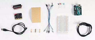
There are many cameras that you can use. Of course, to know how to make a 3D scanner from a phone with your own hands, you need to calculate what you will need for this. If you plan to use the Pi Scan to control cameras, then you should use the Canon PowerShot ELPH 160. But if you are using some other setup, then here are some general recommendations for choosing cameras:
- How many megapixels do you need? Measure the items you intend to scan. Aim for the largest average size (don't go for the biggest outliers). For example, most textbooks are 22.86 x 27.94 cm. Now multiply this size by the PPI (pixels per centimeter) you intend to capture. 300 is a safe minimum, although you can't go wrong with more. So in our example - 9 × 300 = 2700. 11 × 300 = 3300. We need an image that is at least 2700 × 3300 = 8,910,000 pixels, or about 9 megapixels.
- What kind of control do you need? If you're just scanning a single book, or scanning an item just for its informational content (as opposed to trying to capture the actual appearance), you don't need very good pictures. If the lighting or camera settings change from shot to shot, you'll still get a quality result.
- Shutter Speed - White Balance ISO Aperture.
- Flash on/off Any custom image processing (sharpening, color enhancement, etc.).
- Focus (ideally the ability to lock focus).
- Impact compensation.
- Magnifying the Image - Most DSLRs allow for all of this type of control; For compact cameras, only Canon Powershot cameras that support CHDK. They allow you to control all these parameters.
A lot depends on the budget. Scanners are sold at the same price as cameras. If you want to do everything yourself, then your budget is limited. Pay attention to the affordable segment of the optics and spare parts market.
- The first challenge encountered when creating a 3D laser scanner is finding a rotating platform. Moreover, it needs to be controlled only using MatLab. Instead of spending a lot of money or time, you can buy a 28BYJ-48-5V stepper motor with ULN2003 drive test module board.
- Next, glue the platform to the stepper motor shaft and place it in the groove inside the holder. The platform should be level with the marble, but keep in mind that the cheaper it is, the more inconsistent the diameters are, which can make things not level.
- If you have a method for producing precise rotation that can be controlled in Mat Lab, set up the camera at any distance and height, and the laser line to the left or right of the camera and the turntable. The laser angle needs to be optimal to cover most of the turntable, but nothing needs to be exact, we'll handle model scale differences in code.
- The most important part to get it working properly is calibrating the camera. Using MatLab's computer vision toolkit, the exact focal length and optical center of a camera can be obtained to within 0.14 pixels.
Please note that changing the camera resolution will change the calibration process values. The main values we are looking for are the focal length, measured in pixel units, and the pixel coordinates of the optical center of the image plane.
Most cheap compact cameras do not have a software interface. They can only be controlled by manual or mechanical triggering. But a team of volunteers has developed software that allows Canon compact cameras to be controlled and configured remotely. This software is called CHDK.
- The CHDK is downloaded onto an SD card, which is then inserted into the camera.
- When the camera starts, CHDK starts automatically.
- Since CHDK never makes permanent changes to the camera, you can always simply remove the dedicated CHDK SD card for normal camera operation.
CHDK is an important prerequisite for the software controllers listed below. The controllers run on a PC or Raspberry Pi and communicate with the CHDK software running on the cameras via USB. With other types of cheap cameras, the only control option is some kind of mechanical or manual trigger through installer programs, as shown above.
Additional software
When photogrammetry software detects a feature in a photo, it tries to find that feature in other images and records the location in all the photos that appear.
- If the object is part of a rotating object, we get good data.
- If the detected feature is in the background and doesn't move while the rest of the object is being scanned, it can cause a disruption in the space-time continuum, at least as far as your software is concerned.
- One is to move the camera around the subject so that the background remains in sync with the movement. This is good for large objects, but it is much more difficult to automate the process.
- A simpler solution is to leave the background without features. This is easier to do for small objects. Add to that the right lighting and you're well on your way to featureless backgrounds.
There are two solutions:
Another tip is to overexpose your images with a stop or two. This allows you to capture more detail in a subject's shadow while simultaneously isolating the background so any remaining background objects disappear into a brilliant white.
- "Arduino". It has pins that are not covered by the LCD screen, making it easy to connect.
- SainSmart 1602 LCD Shield, which has a display and several buttons to control the scanner.
- Stepper motor driver (Easy Driver).
A NEMA 17 stepper motor will rotate the scanned object. With a larger stepper motor (with appropriate driver and power supply), this high-quality DIY 3D scanner could scale up the scanning. A 950 nm IR LED powers the camera. Some popular models of hand-held 3D scanners are based on this principle. You can repeat the construction process with your own hands. We offer several options to choose from.
The most interesting videos on Youtube
The film was in rolls, so flatbed scanners were immediately eliminated due to the need to cut the film.
High-quality scanning at that time cost from $0.6 to $1 per frame, and specialists who confused DPI with DD did not inspire confidence.
Specialized film scanners turned out to be not just expensive, but very expensive, especially if they are equipped with a film transport mechanism.
Industrial film adapters also did not have a transportation mechanism, much less a light source.
It turned out that, having spent, for example, 120 - 150 dollars on an Olympus adapter, something else would have to be attached and screwed to it. In addition, the ready-made adapter might not be in demand when switching to a DSLR camera.
Then I decided to make a film adapter myself, and take a ready-made film transport mechanism as a basis and screw everything else to it.
Through a newspaper of free advertisements, I found several slide projectors at prices ranging from about 3 to 15 dollars and began to choose the most suitable option.
I settled on the Ekran slide projector because it had a very convenient film transport mechanism, which can be used not only for cropping, but also to increase resolution by stitching the resulting image from scans of individual areas (similar to how real scanners do this). In addition, the kit included a very convenient mechanism for backlash-free fastening of the slides.
As a result, I got a frame, a film transport mechanism and a slide loading mechanism.
Now all that remains is to add the camera mount and light source. During the manufacturing and testing process, the design was redone several times, after which this was the result.
Spinscan by Tony Buser: The Basis of All Scanners
You may be interested: Where to put the tablet in the dishwasher: instructions
In 2011, 3D printing genius Tony Buser released Spinscan. This is a homemade open source 3D scanner based on a laser and a digital camera. MakerBot later used ideas from Spinscan to create the closed-source Digitizer scanner.
“Atlas” is a developed project that requires improvements
A 3D scanner describing how it works from Murobo is currently seeking funding on Kickstarter. Like Spinscan, Digitizer and Cyclop, Atlas uses laser line modules and a webcam to scan an object on a rotating platform. Atlas replaces the Arduino Raspberry Pi to integrate control and capture into the device. Like Cyclop, the creator of Atlas promises that it will be an open source project. The $129 sets are sold out, but some remain at $149 and $209.
In 2022, the company aims to release a smartphone-based 3D scanner that will not only display background visibility, but also design the focus when capturing an image. In America, DIY innovations are amazing. If you don't know how to make a 3D scanner, use the unfinished version of Atlas. The functionality is quite clear, and developers only need to flash the device and ensure the functionality of those functions that they want to see as a result.
Regular camera
You can use digital SLR cameras for shooting. They allow you to take high-quality universal photos. Moreover, scanning does not require the purchase of professional models of devices. So, the Nikon D5000 with a 12.3 megapixel matrix resolution will also cope with the task. Newer models will offer higher-quality, high-resolution photos, but then you will have to sacrifice image processing time. In addition, most digital cameras have the option of saving images in RAW format without compression; this mode will be needed for more detailed scanning of the selected object.
In principle, even point-and-shoot cameras and smartphone cameras are suitable for scanning a model. Many of them provide the ability to shoot in manual mode, so if a person understands the basics of shooting, less advanced devices can be used.
CowTech Ciclop: new multifunctional device model
The price goes up to $160 (depending on whether you 3D print parts or not). The company is based in the USA. The resolution of finished images reaches 0.5 mm. Maximum scanning volume: 200 × 200 × 205 mm. BQ formed the basis of a DIY 3D scanner kit for a 3D printer. With your own hands, you can modify the model version to create images in four-dimensional space.
CowTech Engineering leveraged funds led by BQ, bringing unique value to the updated model. New opportunities:
- environmental review,
- background capture,
- display lenses in an inverted style.
True to the open source movement, Cowtech has launched a Kickstarter campaign to raise money to put CowTech's version of the original into production. The team set a lofty goal of raising $10,000, but were met with surprise and delight when the community was able to raise $183,000. The CowTech Ciclop DIY 3D scanner kit from a camera and phone was born.
Sketch for Arduino
// FabScan - https://hci.rwth-aachen.de/fabscan // // Created by Francis Engelmann on 7/1/11.
// Copyright 2011 Media Computing Group, RWTH Aachen University. All rights reserved. // // Chngelog: // R. Bohne 01/29/2013: changed pin mapping to Watterott FabScan Arduino Shield // R. Bohne 12/30/2013: added pin definitions for stepper 4 —> this firmware supports the new FabScan Shield V1.1 , minor syntax changes. Steppers are now disabled at startup. // R. Bohne 03/12/2014: renamed the pins 14..19 to A0..A5 (better abstraction for people who use Arduino MEGA, etc.) #define LIGHT_PIN A3 #define LASER_PIN A4 #define MS_PIN A5 //Stepper 1 as labeled on Shield, Turntable #define ENABLE_PIN_0 2 #define STEP_PIN_0 3 #define DIR_PIN_0 4 //Stepper 2, Laser Stepper #define ENABLE_PIN_1 5 #define STEP_PIN_1 6 #define DIR_PIN_1 7 //Stepper 3, currently unused #define ENABLE_PIN_2 11 #define STEP_PIN_2 12 #define DIR_PIN_2 13 //Stepper 4, currently unused #define ENABLE_PIN_3 A0 #define STEP_PIN_3 A1 #define DIR_PIN_3 A2 #define TURN_LASER_OFF 200 #define TURN_LASER_ON 201 #define PERFORM_STEP 202 #define SET_D IRECTION_CW 203 #define SET_DIRECTION_CCW 204 #define TURN_STEPPER_ON 205 # define TURN_STEPPER_OFF 206 #define TURN_LIGHT_ON 207 #define TURN_LIGHT_OFF 208 #define ROTATE_LASER 209 #define FABSCAN_PING 210 #define FABSCAN_PONG 211 #define SELECT_STEPPER 212 #define LASER_STEPPER 11 #define TURNTABLE_ST EPPER 10 //the protocol: we send one byte to define the action what to do. //If the action is unary (like turnung off the light) we only need one byte so we are fine. //If we want to tell the stepper to turn, a second byte is used to specify the number of steps. //These second bytes are defined here below. #define ACTION_BYTE 1 //normal byte, first of new action #define LIGHT_INTENSITY 2 #define TURN_TABLE_STEPS 3 #define LASER1_STEPS 4 #define LASER2_STEPS 5 #define LASER_ROTATION 6 #define STEPPER_ID 7 int incomingByte = 0; int byteType = 1; int currStepper; //current motor: turn a single step void step() { if(currStepper == TURNTABLE_STEPPER){ digitalWrite(STEP_PIN_0, LOW); }else if(currStepper == LASER_STEPPER){ digitalWrite(STEP_PIN_1, LOW); } delay(3); if(currStepper == TURNTABLE_STEPPER){ digitalWrite(STEP_PIN_0, HIGH); }else if(currStepper == LASER_STEPPER){ digitalWrite(STEP_PIN_1, HIGH); } delay(3); } //step the current motor for times void step(int count) { for(int i=0; i 0){ incomingByte = Serial.read(); switch(byteType){ case ACTION_BYTE: switch(incomingByte){ //this switch always handles the first byte //Laser case TURN_LASER_OFF: digitalWrite(LASER_PIN, LOW); // turn the LASER off break; case TURN_LASER_ON: digitalWrite(LASER_PIN, HIGH); // turn the LASER on break; case ROTATE_LASER: //unused byteType = LASER_ROTATION; break; //TurnTable case PERFORM_STEP: byteType = TURN_TABLE_STEPS; break; case SET_DIRECTION_CW: if(currStepper == TURNTABLE_STEPPER){ digitalWrite(DIR_PIN_0, HIGH); }else if(currStepper == LASER_STEPPER){ digitalWrite(DIR_PIN_1, HIGH); } break; case SET_DIRECTION_CCW: if(currStepper == TURNTABLE_STEPPER){ digitalWrite(DIR_PIN_0, LOW); }else if(currStepper == LASER_STEPPER){ digitalWrite(DIR_PIN_1, LOW); } break; case TURN_STEPPER_ON: if(currStepper == TURNTABLE_STEPPER){ digitalWrite(ENABLE_PIN_0, LOW); }else if(currStepper == LASER_STEPPER){ digitalWrite(ENABLE_PIN_1, LOW); } break; case TURN_STEPPER_OFF: if(currStepper == TURNTABLE_STEPPER){ digitalWrite(ENABLE_PIN_0, HIGH); }else if(currStepper == LASER_STEPPER){ digitalWrite(ENABLE_PIN_1, HIGH); } break; case TURN_LIGHT_ON: byteType = LIGHT_INTENSITY; break; case TURN_LIGHT_OFF: digitalWrite(LIGHT_PIN, LOW); break; case FABSCAN_PING: delay(1); Serial.write(FABSCAN_PONG); break; case SELECT_STEPPER: byteType = STEPPER_ID; break; } break; case LIGHT_INTENSITY: //after this point we take care of the second byte if one is sent analogWrite(LIGHT_PIN, incomingByte); byteType = ACTION_BYTE; //reset byteType break; case TURN_TABLE_STEPS: step(incomingByte); byteType = ACTION_BYTE; break; case STEPPER_ID: Serial.write(incomingByte); currStepper = incomingByte; byteType = ACTION_BYTE; break; } Download the Codebender plugin and click the “Run on Arduino” button to flash your Arduino.
All! You've uploaded the sketch to your Arduino directly from the browser!
If you have not used the shield, click the Edit button and:
- Add lines
- Replace the step() function:
#include
const int stepsPerRevolution = 200; // change this parameter to adjust the number of steps per rotation of your stepper motor shaft
Stepper myStepper(stepsPerRevolution, 10, 11,8,9);
void step() {
myStepper.setSpeed(1);
myStepper.step(1);
}
So what's the difference between the CowTech version and the BQ DIY version?
CowTech Ciclop still uses Horus 3D software as it is a fantastic shop for 3D scanning objects. The differences, however, are the slightly different design that the team spent several days developing so that the parts can be 3D printed on any FDM 3D printer.
These same blanks can be used to develop your own devices. The company's 3D scanners and printers only have a small build volume, so CowTech has developed parts that can be printed on any printer with a build volume of 115 x 110 x 65 mm, which is found in almost all 3D printers.
Ciclop from CowTech:
- There are adjustable laser holders.
- CowTech DIY uses laser cutting of acrylic.
BQ Ciclop:
- Models use threaded rods.
- There is no laser cutting of acrylic.
There's nothing wrong with this and the scanners still look pretty similar, but CowTech only intended to improve on the existing design rather than reform it. CowTech sells a scan-ready Ciclop for $159 on its website. Overall this is a great cheap DIY 3D scanner that is very effective for laser triangulation 3D scanning.
Rotary machines and tables for creating scanners
This is because it is based on photogrammetry rather than laser triangulation and is compatible with your smartphone! You can download the 3D printable file to sync devices.
You can make a 3D scanner with your own hands from available materials. You just need to trust the creators of DIY 3D. A simple device that instantly turns your iPhone or Android into a 3D scanner by connecting it to this player. Then, using headphones and a phone camera, it takes more than 50 photos of the object that will be scanned as the turntable rotates.
Once you've taken these images, you can load them into a program like Autodesk ReCap to turn the photos into a full-fledged 3D file.
Overall this is a fantastic creative project and a great DIY 3D scanner for those on a budget.
Microsoft Kinect 3D scanner
It costs even less at just $99 (but is no longer on sale, although the Kinect V2 is still available with Xbox One). Kinect slogan" and surprise your friends.
While Microsoft has responded to demand by creating its own 3D Scan app for the Kinect scanner, there are a number of third-party options that may be preferable. These include:
- Skanect, made by Occupital, which also sells the structure sensor.
- ReconstructMe. It provides a set of tools that allow you to perform 3D scanning for less than $100.
You may be interested in: How to measure the diagonal of a TV: basic methods
The results are not fantastic, but for the price they are quite acceptable. It has been shown to be inferior to traditional protogrammetry options in terms of quality, especially in small details such as small models such as shark teeth. However, for 3D scanner beginners, this is a fantastic entry-level product, especially since you may already have one for the Xbox 360.
Restrictions
Obviously, using the photogrammetry method it is possible to obtain a high-quality 3D model of not every object. The following items cannot be scanned with a digital camera:
- transparent objects;
- objects that have a highly reflective surface, such as mirror or chrome plated;
- very small objects;
- objects whose surface has a large number of small parts, protrusions and recesses, or objects of very complex shape.
Models of monochromatic objects with a very smooth and even surface turn out extremely poorly, because in this case the program will have nothing to “attach” to when calculating a three-dimensional figure. In addition, the subject, of course, must be positioned completely motionless in front of the camera lens. It will not be possible to scan a moving object with high quality.