A simple voltmeter circuit includes a measuring block and a set of resistors. This is a minimal kit, suitable only for making preliminary measurements. With such a tester you can measure the voltage in the outlet or the charge level of the battery. Devices that provide high-class measurements require a more complex circuit diagram. Making a homemade digital voltmeter is quite possible for those who can hold a soldering iron in their hands and know the graphical representation of radio elements.
Voltmeter
What types are there?
Devices of this kind are devices that perform direct readings when determining the voltage value. The main requirement for such devices is considered to be high internal resistance. When connected in parallel to the area where the voltage value needs to be tested, it should not have any effect on it.
If we classify devices that measure voltage, we can highlight the following points:
- feature (principle) of work;
- purpose of application;
- structure and methods of use.
Devices are divided into two types: electromechanical and electronic. The first is a structure that includes an electromechanical mechanism and a device that displays the result. The latter are divided into analog and digital devices.
Attention! The name “electromechanical” means that all these structures: electromagnetic, magnetoelectric and others, produce a deflection of the electrical measuring system under the influence of electricity.
Electromechanical voltmeter of electromagnetic system
Analog devices include an amplifier in addition to a set of shunts. This is a unit that allows you to increase the lower measurement interval and increase Rin, as well as measure DC and AC voltage.
A digital voltmeter displays data in digital format. The circuit allows the voltage to be converted into an electrical code using an analog-to-digital device.
Testers by purpose allow you to perform the following options:
- DC potential difference measurement;
- determining the magnitude of AC voltage;
- impulse voltage measurements;
- phase-sensitive measuring devices;
- universal devices;
- devices of selective (selective) action.
The structure, structure and methods of use allow the use of voltmeters for stationary placement, panel placement and for measurements in the field (portable).
Lovat device
The specified ammeter (digital) is made on the basis of a two-digit counter. The current conductivity of the model is only 2.2 microns. However, it is important to note the high sensitivity of the comparator. The display system is simple and the device is very comfortable to use. The resistors in this ammeter (digital) are of the switched type.
It is also important to note that they can withstand heavy loads. The shunt resistance in this case does not exceed 3 ohms. The current conversion process occurs quite quickly. A sharp drop in voltage can only be associated with a violation of the temperature regime of the device. The permissible humidity of the specified ammeter is as much as 70%. In turn, the maximum resolution is 10 mA.
Microprocessor based voltmeter
How to connect a voltmeter
The operation of such devices is based on the functioning of a built-in microprocessor. The system provides service options that not only provide various testing modes, but also determine the characteristics of the signals under test. The operating memory contains a program that controls the operation of the voltmeter.
Important! Voltmeters are the most suitable instruments for carrying out the entire range of diagnostics that a microprocessor can provide.
Microprocessor voltmeters have the following advantages:
- increased measurement accuracy class;
- simplicity and ease of device control;
- admissibility of working with measured values in the context of mathematical functions;
- internal software self-monitoring of calibration and diagnostics of measurement accuracy;
- maintaining statistics of results.
Block diagram of a voltmeter with a digital processor
An AC millivoltmeter, assembled with your own hands on a microprocessor, will consist of the following components:
- input device: amplifier, filters, attenuator (attenuation unit);
- ADC – analogue to digital signal converter;
- digital result display device;
- device control node.
Often the input unit includes an AC to DC voltage measuring converter.
Information. Digital voltmeters on a microprocessor are testers that have wide measurement limits, manual or automatic selection of the measured range. They can measure not only the voltage of both types of current, but also determine the resistance of resistive elements.
Step-by-step instruction
So
,action one
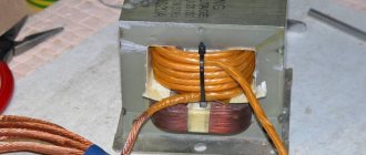
– an SMD resistor with a resistance of 130 kOhm is removed from the circuit, standing at the input of the positive power wire, between the diode and the 20 kOhm trimming resistor.
We connect the resistor to the voltmeter-ammeter Second
. On the free contact, on the side of the trimmer, a wire of the desired length is soldered (for testing, 150 mm is convenient and preferably red) Solder the SMD resistor Third
. A second wire (for example, blue) is soldered to the track connecting the 12 kOhm resistor and the capacitor from the “ground” side.
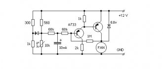
Schematic diagram of a voltmeter
What does a voltmeter measure and how to use it
In order to make an electronic millivoltmeter using an ADC, you can take a microcircuit such as CA3162. A tester assembled according to this circuit allows you to measure voltage in the range from 0 – 100 V. The CA3162E microassembly is an ADC with Uin. Max. = 999 mV. There is also a logical circuit that produces the result in the form of 3 alternating binary-decimal 4-bit codes.
Attention! In this assembly there is a function for polling the circuit capacity during dynamic display. For this purpose, the common terminals of the anodes are used.
Voltmeter circuit for ADC CA31162
Connecting the device
Figure 3 shows a diagram of connecting meters in a laboratory source.
Rice. 3. Connection diagram of meters in a laboratory source.
Fig.4. Homemade automobile voltmeter on microcircuits.
Details
To assemble a voltmeter, the following components are required:
- microcircuits CA31162 and KR514ID2;
- transistors KT361 – 3 pcs.;
- constant resistors with a power of 0.125 W, nominal: 1 kOhm - 4 pcs.; 470 Ohm – 7 pcs.; 470 kOhm – 1 pc.; 4.7 kOhm – 1 pc.; 820 kOhm – 1 pc.;
- variable resistors: 5.1 kOhm (adjustment of the “limit” mode) and 47 kOhm (adjustment of the “zero setting”)
- capacitors: 0.22 mF – 2 pcs.; 6800 pF; electrolytic at 100 mF * 150 V;
- AL324B indicators – 3 pcs.
Parts can be taken used, with leads of sufficient length for successful installation. Key transistors are selected with the same transition resistances or with similar values.
AC Modifications
You can make an AC ammeter (digital) yourself. Microcontrollers in the models are used with rectifiers. To increase the measurement accuracy, broadband filters are used. The shunt resistance in this case should not be less than 2 ohms. The sensitivity of resistors must be 3 microns. Stabilizers are most often installed of the expansion type. It is also important to note that you will need a triode for assembly. It must be soldered directly to the comparator. The permissible error of devices of this type fluctuates around 0.2%.
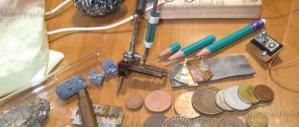
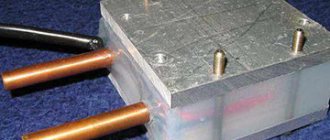
Preparing the board
The parts are mounted on a homemade board made of foil PCB. To secure the elements, holes are drilled in the board. You can make a board on which you can assemble a digital voltmeter yourself. The prepared elements are first placed on a piece of thick cardboard. The leads need to be pierced through the cardboard. After this, the connecting conductors are drawn according to the diagram. Next, the drawing is transferred to the textolite. The connecting tracks are covered with varnish or enamel, after which the board is etched in a solution and washed thoroughly.
The solution is prepared from the following components:
- 100 ml hydrogen peroxide (3%);
- 30 g (1 tbsp) citric acid;
- 5 g (tsp) table salt.
For your information. If necessary, you can add water and heat the solution, this will help the process go faster. This proportion is calculated for a volume of solution that allows processing textolite with an area of 10 cm2.
Connecting the screen
Let's split the connection into two stages. First we connect the right group of pins, then the left one.
Let's go from right to left: connect legs 1, 2, 3, 4, 5 and 6.
Pins 1 ( GND
) and 2 (
UCC
) are responsible for powering the module electronics. Let's connect them to the plus and minus on the breadboard.
Leg 3 ( Uo
) is responsible for contrast control. The easiest way is to simply connect it to the common minus, so the contrast will be maximum.
Legs 4 ( Ao
), 5 (
R/W
) and 6 (
E
) are used to control the screen operating modes. Let's connect the middle one to minus, and the rest to pins 13 and 12 on the Arduino. It sounds confusing, but the connection diagram will help you figure it out.
Unfortunately, it’s not possible to check the screen yet; in order to display at least one point, you will have to connect four more legs. On my module this is the left group of contacts, they are numbered 14 to 11.
These contacts are responsible for transmitting characters that will be displayed on the screen. Study your module carefully and connect them in this order: - 14 ( DB7
) screen pin to pin 8 of the Arduino board, - 13 (
DB6
) pin to pin 9, - 12 (
DB5
) pin to pin 10, - 11 (
DB4
) pin to pin 11 (finally the numbers matched!).
Assembly and configuration
The board is placed in a suitable-sized case and secured with screws. It is also necessary to provide space for the battery and installation of a charging socket. The front panel displays the terminals for connecting measuring probes and the working axes of variable resistors. An indicator for displaying results is also installed outside the housing.
A homemade voltmeter on the CA31162 does not need any special settings. Resistor R4 on the device calibrates “zero” at a similar value of Uin. Resistor R5 calibrates the measurement limits using a previously known value of Uin.
The homemade design of digital voltmeters, made with high-quality components, is not inferior to factory products. Similar circuits can be assembled using ADCs such as KR572PV2, KR572PV5. Instead of a decoder based on TTL logic specified in the diagram, it is permissible to use parts based on CMOS (MOS) logic, having previously coordinated such an assembly with the ADC chip.
Setting up
In general, it is quite simple. Let's start with a voltmeter. First, we connect terminals 10 and 11 of D1 to each other, and by adjusting R4 we set the readings to zero. Then, remove the jumper that closes terminals 11-10 and connect a standard device, for example, a multimeter, to the “load” terminals.
By adjusting the voltage at the source output, resistor R5 adjusts the calibration of the device so that its readings coincide with the readings of the multimeter. Next, we set up the ammeter. First, without connecting the load, by adjusting resistor R5 we set its readings to zero. Now you will need a constant resistor with a resistance of 20 O and a power of at least 5W.
We set the voltage on the power supply to 10V and connect this resistor as a load. We adjust R5 so that the ammeter shows 0.50 A.
You can also perform calibration using a standard ammeter, but I found it more convenient to use a resistor, although of course the quality of calibration is greatly influenced by the error in the resistance of the resistor.
Using the same scheme, you can make a car voltmeter. The circuit of such a device is shown in Figure 4. The circuit differs from that shown in Figure 1 only in the input and power supply circuit. This device is now powered by the measured voltage, that is, it measures the voltage supplied to it as a supply.
The voltage from the vehicle's on-board network through the divider R1-R2-R3 is supplied to the input of the D1 microcircuit. The parameters of this divider are the same as in the circuit in Figure 1, that is, for measurements within 0.99.9V.
But in a car the voltage is rarely more than 18V (more than 14.5V is already a malfunction). And it rarely drops below 6V, unless it drops to zero when completely turned off. Therefore, the device actually operates in the range of 7.16V. The 5V power supply is generated from the same source, using stabilizer A1.
Measurement errors
The measurement error of a voltmeter is directly related to In this case, the pickup voltage at the output should be taken into account. Most often, general interference changes the resistance parameters. As a result, this figure may decrease significantly. Today, there are three proven ways to combat various types of interference in voltmeters. The first technique is to use shielded wires
In this case, it is very important to isolate the input of the electrical circuit from the equipment
The second way is to have an integrating element.
As a result, the interference period can be significantly reduced. Finally, the last trick is considered to be the installation of special filters on voltmeters. Their main task is to increase the resistance in the electrical circuit. As a result, the amplitude of the noise at the output after the block is significantly reduced. It should also be noted that many transducer systems can significantly increase measurement speed. However, as performance increases, the accuracy of data logging decreases. As a result, such converters can cause a lot of noise in the electrical circuit. No tags for this post.
Features of the device
How to make an electronic LED voltmeter-thermometer on a microcontroller for a car from a calculator with your own hands? How to connect a voltmeter with an ammeter in a car to the cigarette lighter? First, let's look at the main features of automotive voltmeters.
The main purpose of the device is to measure the voltage parameter in the automotive network. Analogue and tube devices are equipped with a scale with a pointer indicator, but it is better to install a digital gadget in the car. In such devices, all parameters are displayed. Switch devices are gradually fading into the background; today they are obsolete (video published by the China channel in SHOPe).
Varieties
Voltmeters can be either standard or combined:
- The key feature of standard voltmeters is their fairly small dimensions, which makes it possible to install the device absolutely anywhere in the car’s interior. In practice, such devices are most often connected to the cigarette lighter. With this connection, the voltmeter will be able to record the voltage in the network both when the power unit is running and when it is switched off. In the first case, the operating parameter should be 13.5-14.5 volts, in the second about 12.5 V.
- Combined devices. Such devices can also be equipped with tachometers, ammeters and even thermometers. Combined voltmeters are considered more functional devices, so they are more in demand on the market.
Voltmeter and ammeter for the power supply from the M830B multimeter
Voltmeter and ammeter for power supply from multimeter
The idea of remaking a multimeter to monitor voltage and current arose during the manufacture of the power supply. To indicate voltage, it was supposed to use a dial indicator. I already took it apart and drew a new scale, but I thought about it and decided that a digital indicator would look much better. Once in the magazine “Radio” there was an article on redesigning a computer power supply and there an ADC chip KR572PV2A was used to control the output voltage and current, and LED digital indicators were used to display information. Since the cost of the microcircuit, indicators and parts is comparable to the price of a multimeter, it was decided to remake the multimeter to monitor the voltage and current in the power supply.
The main purpose of the modification was to reduce the size of the board with the indicator, i.e. I just had to cut off part of the board. For the conversion, the simplest and cheapest Chinese multimeter M830B was purchased. The M830B multimeter circuit diagram can be downloaded from our file archive. The voltage measurement limit of our design will be 200 V, and the current limit will be 10 A. To select the “Voltage” - “Current” measurement mode, switch S1 with two groups of contacts is used. The diagram shows the position of the switch in voltage measurement mode.
First you need to disassemble the multimeter and remove the board. You can see the view of the board from the parts side in the photo.
Our design will be placed on two boards. One board with an indicator, another board with parts of the input part of the multimeter and an additional 9-volt stabilizer. The diagram of the second board is shown in the picture. Soldered resistors from the multimeter board are used as divider resistors. Their designations in the diagram correspond to the designations on the board of the M830B multimeter.
The diagram also provides additional explanations. The letters in the circles correspond to the connection points of one board to another. To power the structure, a low-power voltage stabilizer is used, which is connected to a separate winding of the transformer.
Let's actually get started.
Solder R1 8, R9, R6, R5. We save the cuts and edges R 6 and R5 for the input part of our structure.
We cut off the upper contact R10 from the circuit and cut out part of the track (marked with crosses in the photo). Solder R10.
Solder R12 and R11.
R12 and R11 are connected in series. And solder one end to the top contact of R10, and the other to the track cut off from R10. Unsolder R20 and solder it in place of R9.
We desolder R16 and drill new holes for it (see photo)
Turn the board over with the indicator facing you.
Contact R9 (now R20) closest to the indicator is cut off from the circuit (marked with a cross). We connect the contacts R9 (now R20) and R19 farthest from the indicator together (on the indicator side), indicated in the photo by a red jumper.
We connect the upper contact R10 (there are now R11 and R12) to the lower contact R13, indicated in the photo with a red jumper.
We delete some of the tracks marked with crosses. And we solder a jumper to the contact R9 closest to the indicator (now there is R20), instead of the remote track.
We remove the tracks marked with a cross and prepare the contact patches for wiring to the second board, indicated by arrows in the photo.
Solder the jumper.
We solder the contact wires from the second board, observing the correspondence of the letters (aA, bB, etc.)
In this photo, the design is built into the power supply for which it was created. When the load is connected, by pressing the “Voltage-Current” button, the value of the flowing current is displayed on the indicator.
Types of MI by purpose
In accordance with their intended purpose, MI is divided into the following types:
- Soil models designed for underground surveys in the upper layers of soil. Devices in this category are the most common among metal detectors and treasure hunters who can assemble a metal detector with their own hands at home. The simplest homemade product has low accuracy and does not always distinguish between different types of metals. Professional instruments can detect small grains of gold, ignoring other metals.
- Depth models designed to detect targets at a depth of up to 6 meters. However, they can only “see” large objects with an area of over 400 square meters. see. Deep devices are in demand by engineering services as route finders, by geologists as specialized georadars for searching for native gold, etc.
- Underwater metal detecting devices operating underwater. They are subject to increased requirements for the tightness of the search system. The operating conditions of underwater MI in sea and fresh water differ significantly. Underwater detectors use only sound indication.
Note! Underwater MI can be used on the surface in the mode of a conventional ground metal detector. Searchers only need to adjust the length of the rod and the position of the stop to make it more convenient to use the device
- Special metal detectors:
- security devices for detecting metal products in luggage, clothing or on a person’s body during inspection;
- industrial metal detectors as part of conveyor lines, signaling the presence of metals in products;
- military devices, collectively called mine detectors;
- detectors tuned exclusively to gold objects.
In Fig. Below is a hand-held security metal detector.
Security metal detector