The capabilities of a semi-automatic welding machine are significantly higher than those of a machine designed for manual arc welding. A semi-automatic machine can weld much thinner metal.
The use of a special welding wire allows you to work with non-ferrous metals, and the use of shielding gas provides a weld of higher quality. Considering these circumstances, the desire to add such a device to your home workshop is understandable.
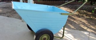
We make a cart with our own hands according to the drawings
Practice has shown that the optimal material for making a do-it-yourself welding trolley is a profile pipe with a cross-section of 20x40 mm and 20x20 mm.
When used indoors on a flat floor, cast wheels are suitable; for outdoor use when moving on the ground, it is better to use pneumatic ones. The design can have certain variations, and we will look at two examples that can be modified in your own way. The cart shown in the photo has two pairs of wheels of different diameters, two shelves for tools and a welding machine, and two places for 10-12 liter cylinders. The bases of the shelves are made of thick plywood.
The drawing does not show all dimensions in centimeters, but those indicated are quite sufficient for a homemade design. The large diameter rear wheels are mounted on M16 bolts welded to the frame. The front wheels are rotating furniture supports. Let's look at assembling the cart step by step:
- First you need to prepare the parts in accordance with the drawings. The frame is assembled from 20x40 pipes; 20x20 pipes are welded to the perimeter platforms as support for plywood sheets and cylinders. All metal must be cleaned before painting.
- First of all, we cook two flat figures of the sides of the cart.
- We weld M16 bolts to the rear of the cart along the axis of the cylinders.
- We install the sidewalls vertically and cook all the horizontal elements. Under sheets of plywood and cylinders we cook tubes with a cross section of 20x20 mm.
- We weld a piece of pipe with a cross-section of 20x40 mm to the rear crossbar of the upper platform for fixing the cylinders. We insert a nut and bolt into it and weld it to the inner walls of the pipe.
- We turn the frame over and cook the front supports from below. We clean the welding areas.
- We wrap the wheel supports and bolts in polyethylene, degrease and paint the metal. We hammer plastic plugs into the ends of the pipes. We install the rear wheels and plywood platforms.
- We place equipment and tools. We install the cylinders in the sockets and fix them with a cross member made of a 20x40 mm pipe and a bolt that is wrapped in a nut welded to the frame.
Probably for safety reasons, it is more correct to install the front supports with clamps. They are a little more expensive than usual, but the cart will not roll away on uneven surfaces. You can learn more about the assembly process using the following video.
Implementation of the electrical part
For this you will need:
- two automotive relays;
- diode;
- PWM regulator for the engine;
- capacitor with transistor;
- idle solenoid valve - for supplying gas to the burner. Any VAZ model will do, for example from a V8;
- wires.
The wire and gas supply control circuit is quite simple and is implemented as follows:
- when you press the button on the burner, relay No. 1 and relay No. 2 are activated;
- relay No. 1 turns on the gas supply valve;
- relay No. 2 works in tandem with a capacitor and turns on the wire feed with a delay;
- wire pulling is done with an additional button, bypassing the gas supply relay;
- To remove self-induction from the solenoid valve, a diode is connected to it.
- It is necessary to provide for connecting the burner to the power cable from the inverter. To do this, next to the Euro connector, you can install a quick-release connector and connect it to the burner.
The semi-automatic device has the following operating sequence:
- The gas supply is turned on.
- The wire feed starts with a slight delay.
This sequence is necessary so that the wire immediately enters the protective environment. If you make a semi-automatic machine without delay, the wire will stick. To implement it, you will need a capacitor and a transistor through which the motor control relay is connected. Operating principle:
- voltage is applied to the capacitor;
- it is charging;
- current is supplied to the transistor;
- the relay turns on.
The capacitance of the capacitor must be selected so that the delay is approximately 0.5 seconds - this is enough to fill the weld pool.
After assembly, the mechanism must be tested, and the manufacturing process can be seen on video.
Mechanical control circuit
To achieve good quality seam when welding, it is necessary to ensure wire feed at a certain and constant speed. Since the motor from the windshield wiper is responsible for the feed speed of the equipment, a device is needed that can change the speed of rotation of its armature. For this, a ready-made solution is suitable, which can also be purchased in China, and it is called
Below is a diagram from which it becomes clear how the speed controller is connected to the engine. The controller regulator with a digital display is located on the front panel of the case.
Next, you need to install a relay that controls the gas valve
. It will also control the engine start. All these elements must be activated when the start button located on the burner handle is pressed. In this case, the gas supply to the welding site should be ahead (by about 2-3 seconds) of the start of wire feeding. Otherwise, the arc will ignite in the environment of atmospheric air, and not in the environment of the protective gas, as a result of which the electrode wire will melt.
A delay relay for a homemade semi-automatic machine can be assembled based on an 815 transistor and a capacitor
. To get a pause of 2 seconds, a capacitor of 200-2500 uF will be enough.
Advice! Since the power comes from a computer power supply, which produces a voltage of 12 V, instead of making the module yourself, you can use a car relay.
It is placed in any place where it will not interfere with the operation of the moving units, and is connected to the circuit according to the diagram. You can use an air valve from GAZ 24 or buy a special one designed for semi-automatic machines. The valve is responsible for the automatic supply of protective gas to the burner. It turns on after pressing the start button located on the semi-automatic burner. The presence of this element significantly saves gas consumption.
But as already noted, the current-voltage characteristics (CV) of the inverter are not suitable for full-fledged operation of a semiautomatic device. Therefore, in order for a semi-automatic attachment to work in tandem with an inverter, minor changes need to be made to its electrical circuit.
How to adjust the feed mechanism?
Schemes of homemade welding machines imply the presence of a special welding wire feeding mechanism for semi-automatic machines. If there is no blank for this element, you can assemble it yourself according to the drawings.
To do this, you will need to take two bearings, the size of which must correspond to standard size 6202, you will also need an electric motor from car wipers, and the smaller its size, the better.
When selecting a welding machine and its compliance with the semi-automatic welding circuit, it is necessary to carefully check that it rotates strictly in one direction. In addition, you will need to take a roller with a diameter of exactly 25 mm. It is placed over the threads on the electric motor shaft. All non-standard structural elements are produced independently - this will make it much easier in the future to repair semi-automatic welding machines with your own hands.
The feed mechanism includes two plates on which bearings are mounted. Between them there is a roller with an electric motor connected to it. The plates are compressed by a spring; the same element of the homemade feed mechanism circuit allows the bearings to be pressed against the roller. The mechanism is assembled on a special textolite plate, its thickness is about 5 mm. This is done in such a way that the welding wire comes out of the mechanism in the area of the connector.
This connector, in turn, will connect to the welding sleeve mounted on the front of the housing. A coil with wound wire is connected to the same plate. In order for the reel to hold well on the feed mechanism, a special shaft is made under it, which is attached perpendicular to the textolite plate. A thread should be cut from the edge of the shaft so that the coil fits onto it as tightly as possible.
The schematic diagram of a semi-automatic welding machine, manufactured independently, is practical, reliable and economical. It is worth noting that the design will probably not look very attractive, but in terms of its operational characteristics it will be practically no different from professional industrial equipment.
All elements located in the feed mechanism are designed for a standard reel. However, this design has one serious drawback - welding work will be carried out without gas.
Feeder
The electrode wire must be fed continuously and evenly - then the welding will be of high quality. The feed speed must be adjusted. There are three options for making the device:
- Buy a fully assembled mechanism. Expensive, but fast.
- Buy feed reels only.
- Do it all yourself.
If the third option is chosen, you will need:
- two bearings, guide roller, tension spring;
- motor for feeding wire - a motor from windshield wipers will do;
- metal plate for fastening the mechanism.
One pressure bearing - it should be adjustable, the second serves as a support for the roller. Manufacturing principle:
- holes are made on the plate for the motor shaft and for mounting bearings;
- the motor is fixed behind the plate;
- a guide roller is put on the shaft;
- bearings are fixed at the top and bottom;
It is best to place the bearings on metal strips - one edge is bolted to the main plate, and a spring with an adjusting bolt is connected to the other.
The completed mechanism is placed in the housing so that the rollers are located in line with the burner connector, i.e., so that the wire does not break. A rigid tube must be installed in front of the rollers to align the wire.
Refinement of the inverter
A semi-automatic welding inverter can be made if its transformer is slightly modernized. For these purposes, the inverter is chosen so that it can supply a current for welding of at least 150 A. The device cannot be used in its finished form due to the discrepancy between the current-voltage characteristics and the conditions for welding with electrode wire in a shielding gas.
Functional diagram of an inverter semiautomatic device
To obtain the required output parameters, it is enough to wrap the transformer with a strip of copper with thermal paper insulation. You won't be able to use a thick wire because it gets very hot. The secondary winding should have three layers of sheet metal, insulated with fluoroplastic tape. The ends are connected to each other by soldering in order to increase current conductivity.
The unit will become very hot during operation. Especially in the radiator area, where you need to install a temperature sensor to ensure that the device automatically turns off in case of overheating.
After turning on the semi-automatic device, the indicator should show a current of 120 A, which will confirm the correctness of the modification and connection. It happens that eights appear on the scoreboard. This happens when the voltage in the welding circuit is low.
Semi-automatic Sanych
Craftsman Sanych offers a semi-automatic welding circuit that is simple and accessible even for beginners.
The proposed design is characterized by a soft hiss of the arc, while crackling and clicking noises are observed in magazine devices. The hard mode is obtained there due to the output characteristics of the transformer 18–25 V.
The transformer consists of four cores from the TS-270 connected together. The result is almost 2 thousand watts. This power is sufficient with reserve. The primary winding (180+25+25+25+25) is made of wire with a cross-section of 1.2 mm. For the secondary (35+35 turns) an 8 mm² bus is used. The number of turns of the secondary winding is determined last, so it is better to make a couple of turns in each arm with a reserve. The excess can be rewinded.
Welding device diagram:
The rectifier circuit is full-wave. To switch the current there is a paired bib. Two diodes in a small radiator. It is recommended to take capacitors of at least 30 thousand microfarads.
The power part is switched on by any of the powerful contactors, for example models KM-50D-V or KP-50D-V. With the passport data 27 V and at 15 V they work stably. The contactor allows you to obtain high switching power at the lowest current of 300–400 mA.
Read also: Homemade reversible plow for a mini tractor
The TS-40 supply transformer is rewound to give an output voltage of 15 V.
For the broaching mechanism, a roller with a diameter of 25–28 mm is used. On the guide you need to make a groove 0.5 mm wide by 1 mm deep. It is secured to the motor shaft with a nut. The output of the regulator is 6 V, and this is enough for optimal supply. If the lower limit is exceeded, a stabilizer with a lower operating voltage is selected.
The handle holder is machined from textolite sheets 10 mm thick. The seats are made with a drill using drills and an end mill.
The protection hose is held in place on both sides by spacer sleeves. For reliability, there are grooves on the mating parts.
The body will require a 1 m thick sheet of iron with a double flange along the edge. The cooling fan is installed on the rear wall, just opposite the power transformer. The semi-automatic welding machine moves on wheels.
The assembled semiautomatic device is connected to the network for testing. It should not overheat and clearly respond to current adjustment. The transformer insulation is also checked. In case of problems, additional coating is applied. You also need to check the feeding mechanism: how evenly and quickly it feeds the wire. The device has worked faithfully for more than 10 years.
The capabilities of a semi-automatic welding machine are significantly higher than those of a machine designed for manual arc welding. A semi-automatic machine can weld much thinner metal.
The use of a special welding wire allows you to work with non-ferrous metals, and the use of shielding gas provides a weld of higher quality. Considering these circumstances, the desire to add such a device to your home workshop is understandable.
Repair or modification of the electrode wire feed speed device
The advertised quality of welding machines usually significantly pumps up the wire feed regulator, so it often requires repair.
Failure of this element causes serious disruptions in the further operation of welding machines; at best, this is a loss of time and the need to replace the welding wire.
Video:
Since the wire gets stuck when leaving the device nozzle, you need to remove the nozzle and clean the contact area.
A failing wire feed control also indicates when the electrode wire is fed too quickly in large chunks or too slowly.
The control regulator may also stop working due to a mechanical failure.
The circuit that the wire feed control regulator has includes a pressure roller that has a wire pressure level regulator, and also a wire feed roller - it has 2 recesses for electrode wire with a diameter of up to 1 mm.
A solenoid is placed behind the regulator - it is used to control the gas supply.
Since the regulator is heavy in design, and is often mounted on the panel of the device with only a few bolts, we can say that the supply regulator is in the air. Video:
For this reason, the design of the semi-automatic device may become distorted, resulting in the need for repair.
You can get rid of this drawback if you repair the semi-automatic device and make a stable stand for the regulator.
Semiautomatic from inverter
There are several ways to make a working semi-automatic device from an inverter. We will list the most interesting, in our opinion. You can implement them at home with basic knowledge of electrical engineering.
Method No. 1
To make an inverter semi-automatic welding machine with your own hands, you will need a “donor”. Without it, it’s simply not possible to make a semi-automatic machine. As a “donor”, take not the weakest inverter for MMA welding. It must be operational and perform normal welding operations without any problems.
You need to change the current-voltage characteristics of the inverter you have chosen so that it can operate in semi-automatic welding mode. You can use a PWM controller for this. However, this option is very labor-intensive and is not suitable for those who are not strong in electrical engineering.
Therefore, in order to assemble a semi-automatic welding machine from an inverter with your own hands, we recommend making a choke. A choke from a fluorescent lamp is suitable for this. And after the throttle you need to take the feedback voltage. Watch the video below, which explains the essence of this method in detail. There is also a clear diagram in the video.
Method No. 2
The second method is extremely simple and is suitable for those who have a certain inverter welding. The fact is that there are inverters on sale that can switch to a mode with a rigid change in the current-voltage characteristic. If you are the owner of just such an inverter, then you can only be happy for yourself. To turn such a device into a semi-automatic machine, you just need to purchase an external feed mechanism.
The mechanism must include all the necessary cables and connectors. You just need to easily connect the welding wire feeder to the welding inverter and you can start welding. We can assume that in this case the feed mechanism works as an attachment to the inverter for semi-automatic welding. Watch the video below, where the author talks about his inverter, to which he connected the feeder.
Method No. 3
The last method of converting from a welding inverter into a semi-automatic machine with your own hands will require some knowledge and skills. In this case, you will also need a donor inverter. Please note that not every device will work. You need an inverter with ZX-7 layout. It must have a shunt at the output, and there must be a current transformer at the “primary”. It’s even better if the device doesn’t have any additional functions like hot start or arc force.
You also need to change the current-voltage characteristics, and also set the current rise setting. Further actions directly depend on the circuit of your inverter. So don’t be lazy to find topics on various forums dedicated to converting an inverter into a semi-automatic machine. Watch the video below with a test of such a homemade device.
Preparation
Manufacturing a semi-automatic welding machine at home begins with planning the work. There are two options for making MIG welding from an inverter:
- Completely make a semi-automatic welding machine with your own hands.
- Only remake the inverter - buy a ready-made feeding mechanism.
In the first case, the cost of parts for the feeding device will be about 1000 rubles, excluding labor, of course. If a factory semi-automatic machine includes everything in one case, then a homemade one will consist of two parts:
- Welding inverter.
- Box with feeding mechanism and wire reel.
First, you need to decide on the body for the second part of the semi-automatic device. It is desirable that it be light and roomy. The feeding mechanism must be kept clean, otherwise the wire will feed jerkily; in addition, the reels must be changed periodically and the mechanism adjusted. Therefore, the drawer should be easy to close and open.
The ideal option is to use the old system unit:
- neat appearance - it doesn’t really matter, but it’s much nicer when the insides of the homemade product don’t stick out and the semi-automatic machine made from an MMA inverter looks good;
- light, closes;
- the body is thin - it’s easy to make the necessary cutouts;
- The gas valve and wire feed drive operate on 12 Volts. Therefore, a power supply from a computer will do, and it is already built into the case.
Now you need to estimate the size and location of future parts in the body. You can cut out approximate layouts from cardboard and check their relative position. After this, you can begin work.
The best option for electrode wire is a 5 kg coil. Its outer diameter is 200 mm, inner diameter is 50 mm. For the axis of rotation, you can use a PVC sewer pipe. Its outer diameter is 50 mm.
Burner
A homemade semi-automatic machine must be equipped with a burner. You can do it yourself, but it’s better to buy a ready-made kit, which includes:
- Burner with a set of tips of different diameters.
- Supply hose.
- Euro connector.
A normal burner can be purchased for 2-3 thousand rubles. Moreover, the device is homemade, so you don’t have to chase expensive brands.
What to look for when choosing a kit:
- what welding current is the torch designed for;
- the length and rigidity of the hose - the main task of the hose is to ensure free flow of wire to the torch. If it is soft, any bend will slow down the movement;
- springs near the connector and burner - they prevent the hose from breaking.
Assembly of a rectifier based on a diode bridge
Diode bridge circuit
Making a homemade semi-automatic device powered by a household AC network requires the installation of a diode bridge. Equipping a single-phase transformer with a secondary voltage rectification device graphically looks like a symmetrical transfer of the lower sinusoids relative to the abscissa axis to the upper quadrants of the coordinate system.
After the rectifying device, the voltage ripple reaches 100 Hz. Twice during a period, an uncontrolled voltage drop from maximum to zero is not capable of maintaining stable combustion and ignition of the welding arc. This flaw is eliminated by a filter, a device designed to smooth out surges in voltage ripple.
Making a homemade semi-automatic machine at home
Assembling a semi-automatic welding machine with your own hands based on an inverter is the preferred option. The welding device is suitable for creating permanent connections from ferrous metals and corrosive steels.
The power source will become the main consumable item. An inverter is an electrical device for converting voltage downward, changing the current value to the level of a welding arc. In fact, this is a voltage generator with a smoothed sinusoid.
Required device components:
- A current source consisting of a high-frequency transformer and a rectifier.
- Electronic module for regulation and process control.
- Wire feed mechanism and reel.
- Inert gas cylinder and hose.
- Burner.
Self-production will not save the craftsman from purchasing ready-made elements. It is difficult to balance the processes of energy conversion and the feed rate of filler material from disparate random components. The wire feed is rigidly tied to the current strength. The arc activity determines the amperage.
Power transformer
The modernized 1-kilowatt OSM-1 was tested and showed effective operation. The reel frame is reinforced with a 2 mm thick textolite gasket. A rectangular window 87x51.5 mm is milled into the cheeks.
The wire for the primary winding is selected with reinforced insulation, preferably fiberglass, Ø1.8 mm. As an option, use enameled wire PEV, PETV. Winding is carried out with uniform tension.
Impregnate the coil with enamel wire with varnish by long (6–10 hours) soaking.
The packing density guarantees the placement of 224 turns (164+15x4) with insulation laid on each layer. You can use thermal paper the old fashioned way, but thin fiberglass is more reliable.
An aluminum or copper busbar in glass insulation is used for the secondary winding. Consumption is within 8 m. A 30 mm mounting end is produced, 19 turns are laid, a closed loop is formed for an M6 screw, and another 19 turns are added.
If you plan to use the welding device on large parts with increasing current strength, add 3 turns to each secondary arm.
Testing the transformer assembly. The no-load current rating is 0.5 A, the voltage on the secondary winding is optimally within the range of 19–26 V. The first part of the semi-automatic device has been manufactured.
Semiautomatic from inverter
We will get a semi-automatic welding inverter after modifications. The transformer is wrapped in 2 layers of copper busbar with the rows insulated with thermal paper, fiberglass or fluoroplastic tape.
On the secondary winding we add 3 layers of unalloyed steel tape in reliable insulation. Both parts of the winding are soldered together. The current conductivity of the winding increases.
We will receive a professional welding device after modernization. The current-voltage characteristic of the inverter is unstable and floats. We achieve a constant voltage output.
Fixed resistors are installed in front of the welding current control shunt. We obtain stable output voltage. The inconvenience of complicating arc adjustment is eliminated by a variable resistor at the output of the shunt.
Setting the arc voltage control is a privilege of professional semi-automatic welding machines. The welder gets a choice when switching the toggle switch to strict current or voltage control mode.
Throttle
A 0.4 kW OSM-0.4 transformer is suitable for winding the inductor. We take an enamel wire Ø1.5–1.8 mm, wind 2 layers with an insulation gasket. 24 turns of aluminum or copper busbar are laid on top with the ends released for installation. The core is assembled with a gap of 1 mm. Accuracy and reliability will be ensured by a textolite gasket.
Required Components
To make a semi-automatic garage welding machine with your own hands, you will need the following:
- Burner attachment for inverter.
- Wire feed mechanism.
- Durable internal welding wire hose.
- Bobbin with wire.
- Sealed gas supply hose.
- Inverter control unit.
The easiest way is to place the inverter and mechanical control unit in a separate box, for which they use blocks from an old computer. The presence of power in the system unit can significantly simplify the manufacture of equipment.
The roller mechanism for the wire can be made from a motor from a car windshield wiper. For such a motor, a mechanism frame is designed, which is cut out of metal elements and welded or bolted together.
You can make a burner and hose yourself from a gun using polyurethane foam and silicone. You can also purchase ready-made kits, which will ensure the safety of working with a semi-automatic device and simplify its manufacture.
When making a wire feed mechanism, all used components must be placed opposite each other, which will subsequently ensure uniform feeding of flexible electrodes. The rollers should be centered relative to the fitting in one connector, in the future this will allow you to smoothly change the wire feed speed. A diagram of the wire feed speed regulator for a semi-automatic welding machine can be easily found on the Internet.
All metal elements used should be secured to a sheet of plywood, thick plastic or textolite. Since electricity is supplied to the metal elements used, the grounding of each node should be checked. This will eliminate the possibility of short circuits, which can lead to serious equipment breakdowns.
How does a standard semi-automatic machine work?
The principle of its operation is a simple and understandable algorithm. That you don’t have to be a specialist or a great scientist to understand it.
First, the torch is directed into the welding area by the worker, at the same time the welding wire is fed into the torch, and along with it, the shielding gas is supplied. This happens in semi-automatic mode, which makes the process quite comfortable.
As a result, between the parts that need to be fused and the welding mechanism there is a mixture of gases in which a discharge is created, which in turn provokes the melting of the metal. Then mixing with the molten wire occurs and a seam can be formed.
This principle is quite clear and does not require special skills to perform; you only need a wire and a gas cylinder. We have already found out why the wire is needed, and the gas is needed to protect the welding zone from possible oxidation.
Principle of operation
The included gas torch for the semi-automatic machine is an actuator for producing a welding seam in a shielding gas environment.
Gas burner for semi-automatic machine
- The torch is placed to the base metal at the arc formation distance.
- Before the arc starts, shielding gas is supplied to the welding zone for a few seconds.
- Voltage is supplied to the current-carrying tip, and accordingly to the electrode wire.
- In the welding arc, the electrode wire melts and drops with the gas flow into the weld pool.
- When the torch moves along the elements being connected, a weld seam is formed.
- The protective gas environment ensures a high-quality and clean seam.
During welding work, torch elements are exposed to high temperatures. Particularly affected are the gas nozzle, the current carrying tip and the electrode holder, also called the diffuser and gas divider.
Burner device for semi-automatic machine
- burner base;
- insulating ring;
- electrode holder;
- current carrying tip;
- gas nozzle.
Failure of, for example, the current-carrying tip prevents the supply of welding wire to fill the pool.
Assembly of a rectifier based on a diode bridge
Diode bridge circuit
The manufacture of a homemade semi-automatic device powered by a household AC network requires the installation of a diode bridge. Equipping a single-phase transformer with a secondary voltage rectification device graphically looks like a symmetrical transfer of the lower sinusoids relative to the abscissa axis to the upper quadrants of the coordinate system.
After the rectifying device, the voltage ripple reaches 100 Hz. Twice during a period, an uncontrolled voltage drop from maximum to zero is not capable of maintaining stable combustion and ignition of the welding arc. This flaw is eliminated by a filter, a device designed to smooth out surges in voltage ripple.
From a welding transformer
If you have an old welding transformer at your disposal, it can serve as the basis for assembling a semi-automatic machine with your own hands.
If the old device has a rectifier and successfully cooks with direct current, nothing else needs to be done in this part. If it is just a transformer for AC welding, it should be modified.
Diode bridge
In order to obtain a source of direct current for welding, the transformer must be equipped with a diode bridge and a filter. The diode assembly rectifies the secondary voltage, the filter smoothes out ripples, maintaining stable arc burning.
The rectified voltage of a single-phase transformer has the form of a sinusoid, the lower half-waves of which are reflected symmetrically to the abscissa axis and moved to the upper quadrants of the coordinate system.
Essentially, this is a voltage pulsating at a frequency of 100 hertz, reaching zero twice per period. Using such a voltage for welding as a constant voltage leads to an unstable arc. To eliminate this phenomenon, a filter is required to smooth out voltage dips.
Filter
The filter consists of a choke connected in series to the welding circuit and a capacitor connected in parallel. This combination of inductance and capacitance is called an L-shaped filter, because in the diagram, the elements connected in this way form the letter L.
The capacitor for the future semiautomatic device needs an electrolytic, polar, capacity of 10,000 microfarads, the more the better. The capacitor voltage must be at least 100 volts to have a good margin. You can solder several capacitors in parallel, and the capacitance is summed up.
Throttle
To wind the inductor with your own hands, you need to find an old transformer of suitable dimensions. A power transformer from old tube color TVs with a power of at least 250 watts is well suited for this purpose.
The transformer has two coils on an oval closed core consisting of two halves. The transformer is disassembled, the coils are removed, and the old wire is removed from them.
For winding, a suitable flat copper busbar is selected. On each coil, instead of the removed wire, two layers of turns of a copper bus are wound by hand. The coil should have 15 - 20 turns.
After this, the steel core is assembled, the coils are put in place, and a 1.5 mm thick textolite gasket is inserted between the halves of the core. The coils are connected in series.
Broach
You can build a wire drawing mechanism for a semi-automatic machine with your own hands, using small bearings and an electric motor from car wipers.
But it is better to buy a ready-made one; it is sold as a spare part for semi-automatic welding machines. You will also have to buy a torch and a hose through which wire and gas will be supplied.
Setting up an inverter used for semi-automatic welding
If you decide to make a semi-automatic welding machine with your own hands using an inverter, you must first turn off the power to this equipment. To prevent such a device from overheating, its rectifiers (input and output) and power switches should be placed on radiators.
Power diodes on additional radiators
After all of the above procedures have been completed, you can connect the power part of the device to its control unit and connect it to the electrical network. When the network connection indicator lights up, an oscilloscope should be connected to the inverter outputs. Using this device, you need to find electrical pulses with a frequency of 40–50 kHz. The time between the formation of such pulses should be 1.5 μs, which is regulated by changing the voltage value supplied to the device input.
Oscillogram of welding voltage and current: on the left with reverse polarity, on the right with direct polarity
It is also necessary to check that the pulses reflected on the oscilloscope screen are rectangular in shape, and their front is no more than 500 ns. If all the checked parameters correspond to the required values, then you can connect the inverter to the electrical network. The current coming from the output of the semi-automatic device must have a force of at least 120 A. If the current value is less, this may mean that voltage is supplied to the equipment wires, the value of which does not exceed 100 V. If such a situation occurs, you must do the following: test the equipment by changing the current (in this case, it is necessary to constantly monitor the voltage on the capacitor). In addition, the temperature inside the device should be constantly monitored.
After the semi-automatic machine has been tested, it is necessary to test it under load. To make such a check, a rheostat is connected to the welding wires, the resistance of which is at least 0.5 Ohm. Such a rheostat must withstand a current of 60 A. The strength of the current that in such a situation flows to the welding torch is controlled using an ammeter. If the current strength when using a load rheostat does not meet the required parameters, then the resistance value of this device is selected empirically.
Housing assembly
At the next stage, you can begin assembling the installation body. To do this, you can use iron, the thickness of which is 1.5 mm; the corners must be connected by welding. It is recommended to use stainless steel as the base of the mechanism.
The role of the motor can be the model that is used in the windshield wiper of a VAZ-2101 car. It is necessary to get rid of the limit switch, which works to return to the extreme position. The bobbin holder uses a spring to obtain braking force; for this, you can use absolutely any one that is available. The braking effect will be more impressive if it is influenced by the compressed spring, for this you have to tighten the nut.
In order to make a semi-automatic machine with your own hands, you need to prepare the following materials and tools:
- enamel wire;
- wire;
- single-phase machine;
- transformer;
- welding torch;
- iron;
- textolite
Making such an installation will be a feasible task for a craftsman who has familiarized himself with the recommendations presented above in advance. This machine will be much more profitable in terms of cost compared to the model that was produced at the factory, and its quality will not be lower.
In its simplest form, a choke is a coil of thick copper wire wound around a magnetic core, which is connected to the output circuit of the welding machine in series with the electrode. A choke for a semi-automatic device is necessary to smooth out current ripples that occur during short-term changes in the input voltage and instantaneous short circuits on the electrode. When performing semi-automatic welding without this device, there is a high probability of weld defects occurring, since with such deviations in electrical parameters, the wire continues to feed at a constant speed.
Any home craftsman can make a choke for a semi-automatic machine. Its calculation is carried out in a very large scale (mainly in terms of wire cross-section), and the parameters of a homemade choke are selected by adjusting the core gap during trial activation of the semi-automatic device in different modes. However, it is still advisable to have at least a general understanding of the basic electrical principles underlying the operation of this device, as well as the design features of its manufacture.
The operation of the choke of a semi-automatic welding machine is based on the so-called “first law of switching”, according to which the current in the inductor cannot change instantly. In a very simplified form, we can say that the inductor acts as a kind of energy storage device, but unlike a capacitor, it accumulates not voltage, but current. When passing through the coil, the flow of electrons generates a magnetic field, the magnitude of which depends not only on the current strength, but also on the parameters of the core. By adjusting the gap between its elements, you can control the magnitude of the magnetic flux and thus regulate the inductive reactance of the inductor.
The inductance value of the inductor directly affects the rate at which the current increases during a short circuit. Moreover, it directly depends on the semi-automatic welding mode and the wire diameter. When using thin wire, a faster rise in current is required and, accordingly, less inductance than when using thick wire. For example, when the wire diameter is reduced by one and a half to two times, the inductance decreases by 2.5–3 times.
Tools and materials
To make a semi-automatic welding unit from an inverter (AC-to-DC converter) with your own hands, you need to prepare the required components and equipment.
- Inverter with an output current of 150 A.
- Filler material (additive) supply device.
- Gas burner gun.
- A supply hose, which will become a guide channel for the filler material going to the area to be welded.
- Hose for supplying protective gas mixtures to the welded area.
- Reel (reel) with filler material (wire).
- Electronics unit for monitoring the activities of a semi-automatic welding unit. Here the electric current strength, voltage and operating speed are adjusted.
- Scheme of a semi-automatic welding device.
Types and classification
Based on their intended purpose, devices are divided into professional and household.
The first include:
- Burners for work related to metal processing: soldering, forging, welding.
- Devices for general construction, road work, roofing, wood burning, and removal of old paint.
- Technological equipment for various purposes. For example, drying chambers, food industry tools.
For household purposes, this includes a gas stove, nozzles for home stoves, heating boilers, and gas convectors.
Household devices include home workshop devices . This is where you most often find do-it-yourself burners, not only manufactured, but initially designed to perform specific tasks.
They are arranged according to two main schemes:
- injection or injection,
- with complete preliminary mixing of the working mixture, or ejection.
In the first type, air (or oxygen) is captured by the supplied gas stream. In the latter, the gas-air mixture is obtained in a preliminary chamber.
Throttle
As a core you will need a TCA 270-1 tube TV transformer. We remove the coils. To create an inductive gap to the base of the horseshoe-shaped elements, we glue textolite spacers 1.5 mm thick.
Throttle
The inductor is wound onto the freed coils. Instead of the removed wire, a copper busbar is laid in 2 layers on thermal paper. The number of turns must be the same, optimally 15–20. We impregnate it with bakelite varnish. We assemble the metal core. We install the coils.
At the bottom is the input after the diode bridge and the output to the ground cable, at the top is the series connection of the elements. It happens that after starting the smoothing device, the current strength decreases. The solution is an equal reduction in the number of turns on the coils.
Manufacturing of semi-automatic devices
First, let’s find out what a semi-automatic machine consists of, or rather, its main components. He has a power block and a serving block. The first is the power part, and the second is the feed mechanism. Also, during the welding process, the semi-automatic machine uses one of its parts - filler wire.
It is needed as an electrode, its function is to conduct current in the direction of the formation of the seam and allows this formation to occur. It must be fed into the welding zone; usually for this purpose there is, as mentioned above, a feeding mechanism, but this can also be done manually.
Considering that the semi-automatic machine has only two blocks, that is, the feeder is in a separate state, then the power one too. The latter works as a current source. The power unit also operates on the basis of an inverter.
Among the other elements that make up a homemade tool, we need a torch, a nozzle, and a hose or welding sleeve and some other parts that work with gas. The entire unit may consist of two parts that are not connected to each other.
Therefore, it can hardly be called compact or very convenient to use. This makes a homemade semi-automatic machine worse than the purchased version.
Recommendations
The principle of operation of the device is what you should understand before making the device. You can consider it using the example of a burner for roofing work. How does the burner work?
- The device is connected to the reducers of oxygen and propane cylinders by a system of supply hoses.
- Reducers are placed on the cylinders to create working welding pressure.
- A diagram for gas and oxygen is assembled, the tightness of the connections is checked, the nodes are secured, after which the gas can be opened with valves.
- The gas pressure is set to the operating value and the valve opens.
- The fuel is supplied through hoses to the propane appliance.
- The injector carries out the mixing process to form a gas-air environment.
- A working flame with a temperature reading above 2000 degrees comes out of the device.
Making a burner is one thing, using it correctly is another. A simple burner can cause an explosion or fire.
When performing any welding work, you must wear personal protective equipment: gloves and goggles, special shoes. You can work with propane cylinders only in a well-ventilated area, and at sub-zero temperatures, any actions with the burner are excluded.
What you should absolutely not do:
- work near open fire;
- keep the cylinder tilted;
- place vessels under the sun;
- carry out work without a gearbox;
- Warm up the gearbox over an open fire.
If you can clearly smell the gas, work with the burner should be stopped by closing the valve on the cylinder. Homemade burners, depending on the purpose of use, can be different: burners with a VK-74 valve, devices converted from an acetylene gas cutter and mini gas burners. It is realistic, profitable, and useful to build every homemade device. Only initially you need to decide on the type of structure and its parameters. The gas burner is also used in private households and for commercial purposes. In plumbing, a metal workpiece is heated with a torch, which ultimately comes out quite hardened.
How to make a gas burner, see below.
Important parameters when choosing a semi-automatic welding machine
Having learned the types of devices and the capabilities of working with gases, let’s move on to the key parameters. To understand which semi-automatic welding machine is better to buy for a garage or home workshop, it is worth understanding four characteristics that affect welding capabilities.
Wire diameter and welding current
When choosing a semi-automatic welding machine, you need to start from the thickness of the metal being welded. For car body parts or repairing electrical equipment housings, a low current strength and a small wire diameter are needed to avoid burn-throughs. If you choose a low-power device, it will not melt the sides, but will only put molten metal on top, which will not have a holding force. With a powerful semi-automatic machine, but a small wire diameter, the wire will melt before it reaches the parts being connected.
Here is an approximate table for selecting a semi-automatic welding mode:
| Metal thickness, mm | Wire diameter, mm | Current strength, A |
| 0.5-1.0 | 0.6 | 10 – 30 |
| 1.2-2.0 | 0.8 | 45 – 100 |
| 2.5-4.0 | 1.0-1.2 | 120 – 200 |
| 5.0-8.0 | 1.6 | 150 – 350 |
| 9.0-20.0 | 1.6 | 300 – 500 |
Therefore, if the priority is welding containers and sheet steel with a thickness of up to 2 mm, then the simplest model with a current of 150 A and a coil of wire with a diameter of 0.8 mm is sufficient. But welding a channel with such a semi-automatic machine will no longer work. If in the future you will be welding metals of different thicknesses, then it is better to choose a model with a large range and the ability to install wire of different diameters.
Supply voltage
It is important to take into account the network parameters when choosing a semi-automatic device. Household 220 V models can be connected to a powerful carrying case and cooked in the yard or garage
But they are limited to a current limit of 250 A. To weld at a higher current, a three-phase input will be required. If the garage has such a connection option, then it is worth ordering a 380 V semi-automatic device, which will expand its capabilities. A combined type, capable of switching and operating from both 220 and 380 V, is justified only in the case of field activities, when it is often necessary to change the workplace, and future network parameters are unknown.
But for a private home and cottage, it is also worth considering the possibility of cooking at a reduced voltage. When the current drops from 220 to 190 V and below, some devices simply “do not pull”, the arc barely burns, and the metal in the weld pool looks like plasticine instead of liquid
Then you need to pay attention to models with an input voltage range of 140-230 or 170-230 V
Power consumption
Power consumption affects performance and the load it places on the network. For domestic needs, it is better to choose semi-automatic devices with a power of 3-4 kW. This will help prevent the socket from burning due to overheating, the machine will not knock out, and the indicator will be enough to weld sheet metal or a corner up to 3 mm thick.
If the garage has a small production facility for the production of doors and gates, then a more powerful machine and wiring are needed. Then you can choose a 5-6 kW unit, which expands your welding capabilities. For private workshops, equipment from 7 kW is used.
Considering the power indicator, it is worth remembering that its operating value is slightly lower than the consumed one. Initially, you need to provide a reserve of 20%, but if there are frequent network drawdowns in the house, then this reserve should be even larger.
Housing selection, coil alignment and installation
Before you begin to independently assemble a semi-automatic welding machine, you should decide on a suitable housing option. As an alternative, you can consider a box having the required dimensions, made of sheet metal or plastic. The selected housing will serve as the place where the transformers will be installed, after which it is necessary to connect their primary and secondary bobbins
.
several dozen through holes should be provided in the body of the semi-automatic device you created yourself.
. You can purchase welding cable holders in a specialized store. It is impossible to create a homemade semi-automatic welding machine without a gas cylinder: it can also be purchased in a store or borrowed from an old fire extinguisher. When the investor is connected to the network, the microcontroller will immediately start working and configure the optimal characteristics for welding. If there is a voltage on the cable other than 100 V, we can conclude that the device is faulty. In this case, you will need to diagnose and eliminate the cause.
Self-production of semi-automatic welding machine
Before making a homemade semi-automatic machine, you need to prepare the following equipment:
- To generate an operating current of 150A, you will need a welding inverter, which can be made from a transformer from a microwave oven.
- A burner, which is responsible for dosing shielding gas at the welding site.
- The feed mechanism is responsible for the continuous flow of welding wire to the welding site.
- To control the unit, it is necessary to equip an electrical unit with which the current strength is regulated.
- Using a feed hose, the welding wire is supplied to the working surfaces.
- A gas hose will be needed to supply shielding gas to the connection area.
- Spool of filler wire.
Some components are very difficult to make yourself (burner, cylinder, hoses), so it is advisable to purchase them in a retail chain.
Semi-automatic wire feeding diagram
A transformer is quite suitable for these purposes. It is the simplest and most reliable method of powering an electric motor. The most optimal feed rate control circuit is a thyristor one. Below you can see the electrical circuit with which the feed motor is controlled.
Feeder PCB
This circuit does not have a smoothing capacitor; this is how the thyristor is controlled. The diode bridge can be anything, the main thing is that the current exceeds 10A. We use BTB16 with a flat case as a thyristor; it can be replaced with KU202 (any letter). The transformer, which contains a semi-automatic do-it-yourself welding machine, must have a power exceeding 100W.
What is needed to convert an inverter into a semi-automatic machine?
To convert an inverter into a functional semi-automatic welding machine, you must find the following equipment and additional components:
- an inverter machine capable of generating a welding current of 150 A;
- a mechanism that will be responsible for feeding the welding wire;
- the main working element is the burner;
- a hose through which the welding wire will be fed;
- hose for supplying shielding gas to the welding area;
- a coil of welding wire (such a coil will need to undergo some modifications);
- an electronic unit that controls the operation of your homemade semi-automatic machine.
Electrical circuit of a homemade semi-automatic machine
Special attention should be devoted to redesigning the feeder, through which welding wire is supplied to the welding zone, moving along a flexible hose. In order for the weld to be high-quality, reliable and accurate, the wire feed speed through the flexible hose must correspond to the speed of its melting
Since when welding using a semi-automatic machine, wire of different materials and different diameters can be used, its feed speed must be adjusted. It is precisely this function – regulation of the welding wire feed speed – that the feed mechanism of a semi-automatic device should perform.
Appearance of a homemade semi-automatic welder
The most common wire diameters used in semi-automatic welding are 0.8; 1; 1.2 and 1.6 mm. Before welding, the wire is wound onto special reels, which are attachments of semi-automatic devices, fixed to them using simple structural elements. During the welding process, the wire is fed automatically, which significantly reduces the time spent on such a technological operation, simplifies it and makes it more efficient.
The main element of the electronic circuit of the semi-automatic control unit is a microcontroller, which is responsible for regulating and stabilizing the welding current. The parameters of the operating current and the possibility of their regulation depend on this element of the electronic circuit of the semi-automatic welding machine.
Burner design
There are many manufacturers of welding equipment, but the torch design is the same for everyone. They differ in materials, sizes, critical temperature and power, and mechanisms for supplying a protective medium (gas, flux).
Considering the design of the burner, it is worth noting that the main elements are:
- nozzle;
- holder;
- tip;
- insulating sleeve;
- base with handle.
Burner tips and nozzles are made from different materials and therefore have different service life. Copper is widely used, but the duration of work also depends on its quality. To increase service life, the nozzles are made of tungsten. But at the same time the price increases. The average operating time of such tips and nozzles is 200 hours.
Due to the frequent change of consumables, these elements are made quick-changeable so that the welder can replace them with his own hands in a short time.
The handle is made of heat-resistant insulating material that protects the welder from electric current. There is a button on the handle that turns on the supply of protective gas before igniting the arc.
The handle is connected to the welding machine through a supply hose, which contains the following:
- power cable;
- twisted wire feed channel;
- channel for supplying protective materials;
- cooling circuit;
- connector for connecting to the device and feed mechanisms.
The standardized hose length starts from 2.5 m and reaches 7 m. The length depends on the location and type of work performed. To reach the weld at a height without lifting the apparatus, the sleeve must be of maximum length.
But it is worth remembering that the excess, folded on the floor in rings, when voltage passes through them, works like inductive coils and gets very hot. As a result, a short circuit may occur.