MATERIAL SELECTION
PRODUCTION SEQUENCE
PROPELLER BALANCING
FINISHING AND PAINTING OF THE SCREW
Snowmobiles, airboats, all kinds of hovercraft, ekranoplanes, microplanes and microgyroplanes, various fan installations and other machines cannot operate without a propeller. Therefore, every technical enthusiast who plans to build one of the listed machines should learn how to make good propellers.
And since in amateur conditions it is easiest to make them from wood, we will only talk about wooden propellers. However, it should be taken into account that using wood (if it turns out to be a country house) you can make completely similar screws from fiberglass (by molding into a matrix) or metal (by casting).
Due to their availability, the most widespread are two-blade propellers made from a whole piece of wood (Fig. 1) . Three and four blade propellers are more difficult to manufacture.
How to make a propeller for a motorboat
The first and second parts of a series of articles by V.V. Weinberg, entitled “A propeller for your boat,” were published in collections No. 97 and No. 98.
Devices for making a model of a screw and controlling its shape. None of the modern methods of manufacturing propellers can do without a step slide. It is assembled on a base - a step plate, which is a steel disk 10-15 mm thick (Fig. 1) with a diameter of about 500 mm (according to the maximum diameter of the propellers). Stepping squares are installed on the plate, bent along cylindrical surfaces of given radii. The working surface of the plate is trimmed on a lathe, and circular grooves 3 mm deep and 1-2 mm wide (according to the thickness of the material from which the pitch squares are made) are machined every 10 mm along the radius. A shaft with cones centering the propeller hub is installed in the center of the plate, strictly perpendicular to its surface.
When manufacturing propellers of small diameter, pitch squares are installed in each groove, i.e. with a gap of 10 mm. In this case, it is quite difficult to check the tightness of the blade to the pitch squares and measure the profile concavity arrows in its sections, so we recommend a collapsible design of the pitch plate (Fig. 2). It is assembled from disks with a diameter of 60, 80, 100 mm, etc. (in accordance with the section radii specified in the propeller drawing), cut from a flat plywood sheet 10 mm thick. Holes are drilled in the disks strictly in the center so that they can be tightly seated on the centering shaft. Bandages are made from a metal strip 8-10 mm wide for each disk, which are tightened with an M4 screw, and the corresponding pitch squares are attached.
Pitch angles are formed when the helical surface of the blade intersects with a cylinder coaxial with the axis of the propeller and having a radius of a given section. If the surface of the cylinder is turned onto a plane, you get a right triangle, one leg of which is equal to the pitch of the screw in a given section, and the second is equal to the circumference of the base of the cylinder (Fig. 3). An acute angle located opposite the leg equal to the pitch of the helix is called the pitch angle. The tangent of this angle is equal to the ratio of the legs:
Since only part of the helical surface in the area where the blade is located is required for the manufacture of a propeller, the dimensions of the pitch square can be reduced. To do this, it is necessary to determine the height of the square in the area of the generatrix (middle) line of the blade. This can be done using a drawing of the longitudinal section of the propeller, which shows the dimensions of the blade, the propeller hub and shows the inclination of the generatrix. In the drawing, a line is drawn from the rear end of the hub, perpendicular to the axis of the screw and depicting the base plane of the surface of the step plate. If a prefabricated slab is used, such lines are drawn for each disk. In this case, the gap between the blade dimension line and the step plate should be at least 8-10 mm. The height of the pitch square - dimension A in the drawing - is measured from the base plane to the generatrix of the blade (see Fig. 3). This size should be increased either by the depth of the groove on the step slab, or by the width of the strip required to secure the square with a bandage during the prefabricated structure of the slab.
The size of legs B for constructing pitch angles for each radius is determined by the formula
where Hr is the blade pitch at a given radius and is taken from the pitch distribution graph along the blade.
On the hypotenuse of the pitch square, the position of the blade cross-section is marked: the center line mark, as well as the points of the incoming and outgoing edges. The width of the blade and the position of the section relative to the center line are taken from the drawing of the straightened contour. For the convenience of blade manufacturing, the length of the pitch square should be increased on each side by 10-15 mm. Deviations when marking pitch squares should not exceed ±0.3 mm, and the marks are applied with a sharp scriber.
When marking pitch squares of root sections that have a biconvex profile, it is necessary to remove a strip of metal from the working edge of the square (hypotenuse) with a width equal to the convexity arrow of the discharge side of the profile. This will ensure that the blade blank, which has not yet been profiled, will adhere to the pitch square.
Depending on the propeller manufacturing technology, it is necessary to make a set of squares either for one blade or for all. To ensure symmetry of the finished propeller for a radius close to r=0.6R, it is necessary to make pitch squares for all blades.
When installing pitch squares for all blades of a high-disk-ratio propeller, squares of the same radius may overlap each other. In this case, in the larger vertical leg of these squares it is necessary to make a local cut into which the smaller leg of the next step square fits (Fig. 4).
After marking, cutting, final processing and testing, the squares are bent along cylindrical surfaces of given radii, taking into account the direction of rotation of the propeller.
To install angles on a step plate, draw the center line of the blade - a straight line passing through the center of the plate, and on a prefabricated plate made of individual disks - center lines on each disk.
MATERIAL SELECTION
What wood is best to make a screw from? This question is often asked by readers. We answer: the choice of wood primarily depends on the purpose and size of the screw.
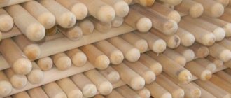
Screws intended for engines of higher power (about 15-30 hp) can also be made from monolithic hardwood bars, but the requirements for the quality of wood in this case are increased. When choosing a workpiece, you should pay attention to the location of the growth rings in the thickness of the block (it is clearly visible at the end, Fig. 2-A ), giving preference to bars with horizontal or inclined layers, cut from that part of the trunk that is closer to the bark. Naturally, the workpiece should not have knots, crooked layers or other defects.
Rice. 2. Propeller blanks
If it was not possible to find a monolithic bar of suitable quality, you will have to glue the workpiece together from several thinner boards, each 12-15 mm thick. This method of manufacturing propellers was widespread at the dawn of the development of aviation, and it can be called “classical”. For reasons of strength, it is recommended to use planks made of wood of different species (for example, birch and mahogany, birch and red beech, birch and ash), having mutually intersecting layers (Fig. 2-B) . Screws made from glued blanks have a very beautiful appearance after final processing.
Some experienced specialists glue blanks from multilayer aircraft plywood of the BS-1 brand, 10-12 mm thick, and assemble a package of the required size from it. However, we cannot recommend this method to a wide range of amateurs: veneer layers located across the screw, during processing, can form difficult-to-remove irregularities and deteriorate the quality of the product. The ends of propeller blades made of plywood are very fragile. In addition, in a high-speed propeller, a very large centrifugal force acts at the root of the blades, reaching in some cases up to a ton or more, and in plywood the transverse layers do not resist breaking. Therefore, plywood can be used only after calculating the root section area of the blade (1 cm2 of plywood can withstand about 100 kg of tearing, and 1 cm2 of pine - 320 kg). The screws have to be thickened, and this worsens the aerodynamic quality.
In some cases, the attack edge of the propeller is covered with a strip of thin brass, the so-called fitting. It is attached to the edge with small screws, the heads of which, after cleaning, are soldered with tin to prevent self-loosening.
Theoretical drawing of a homemade propeller for outboard motors “Vikhr” and “Vikhr-M”
enlarge, 607 KB Propeller characteristics: rotation - right;
diameter - 240; step at r = 0.7D (Hcp) - 240 and 264; number of blades - 3; disc ratio θ=0.51; step ratio at 0.71D (Hcp/D) - 1.0 and 1.1; motor power - 20-25 hp. With.; propeller speed 2600-3000 rpm; material - aluminum alloy. 1 — incoming edge of the blade; 2 — emerging edge of the blade; 3 - line of greatest thickness of the blade; 4 — contour of the lateral projection of the blade; 5 — section of the blade along the line of greatest thickness; 6 — profile of the straightened root of the blade; 7 - blade axis. Tests of a set of propellers for the Whirlwind, the results of which were described in the article Lost Forces, somewhat later continued on the production motorboat Crimea. The program for these tests was drawn up in such a way that it was possible to plot the dependence of the boat’s speed on its load and propeller pitch (the Whirlwind had propellers with a pitch of 240, 264 and 300 mm). The results obtained (the graphs constructed from them are presented in this article) confirm all the previously drawn conclusions. I would like to additionally note only the following: thanks to the work done with adjusting the propeller, during these tests it was possible to set a kind of record: “Crimea” went on planing with a specific load of up to 35 kg/l. s., while in the vast majority of cases for factory-built pleasure and tourist motorboats this figure does not reach 30 kg/l. With.
BALANCING
The manufactured propeller must be carefully balanced, that is, brought to a state where the weight of its blades is exactly the same. Otherwise, when the screw rotates, shaking occurs, which can lead to the destruction of vital components of the entire machine.
Figure 5 shows a simple device for balancing screws. It allows you to perform balancing with an accuracy of 1 g - this is practically enough for amateur conditions.
Rice. 5. The simplest device for checking propeller balancing
Practice has shown that even with very careful manufacturing of the propeller, the weight of the blades is not the same. This happens for various reasons: sometimes due to different specific gravity of the butt and upper parts of the block from which the screw is made, or different densities of layers, local nodularity, etc.
How to be in this case? It is impossible to adjust the weight of the blades by cutting off a certain amount of wood from a heavier one. It is necessary to make the lighter blade heavier by riveting pieces of lead into it (Fig. 6). Balancing can be considered complete when the propeller remains motionless in any position of the blades relative to the balancing device.
Rice. 6. Balancing the propeller by riveting pieces of lead into a lighter blade
Screw runout is no less dangerous. A scheme for checking a propeller for runout is shown in Figure 7. When rotating on an axis, each blade should pass at the same distance from the control plane or angle.
Rice. 7. Scheme for checking the screw for runout
Prop Balance
The already made screw needs to be balanced. That is, to ensure that the weight of the blades matches. Otherwise, when the screw rotates, shaking will occur, leading to serious consequences - all the most important components of your device will be destroyed.
But in practice, it is not uncommon for skilled craftsmen who do not wonder how to make a propeller to find that the weight of the blades varies. And this is even if all the manufacturing nuances are observed! There are many explanations for this: different specific gravity of the various components of the bar from which the screw is made, different layer densities and many other reasons.
Instructions
So, how to make a propeller with your own hands? The process of creating a propeller looks like this:
- First you need to work on the templates, namely: 1 template for the top, 1 for the sides and 12 templates for the blade in profile.
- Plane the screw blank according to the dimensions on all four sides and draw the axis lines and contours of the side view template.
- Remove excess wood. First you do this with a hatchet, and then with a plane and rasp.
- Now place the blade template on the workpiece and secure it with a nail in the center of the sleeve for a while, then trace it with a pencil.
- Rotate the template 180° and trace the second blade. Excess wood can be removed using a fine-tooth saw. This work should be done carefully and not in a hurry.
- Remove the wood without haste, making small and short cuts.
- The screw must be brought to readiness using a plane and rasp and checked in the slipway.
- In order to make a slipway, you need to look for a board that is the same length as the screw size, and also allows its thickness to make transverse cuts of 2 cm in order to install templates. To make the central rod of the slipway you will need solid wood. And its diameter should be the same as the diameter of the hole in the screw hub. The rod should be glued to the surface of the slipway at an angle of 90°.
- Put the propeller on and see how much wood needs to be cut to get the blades to fit the profile templates.
- Once the bottom surface of the screw begins to match the templates, you can begin finishing the top surface. This operation is very important, since the quality of the resulting screw is based on it.
For beginners, it is not uncommon for the blades to not match in size. For example, one turned out thinner than the other. But to make the correct propeller, you will have to achieve equal size by reducing the thickness of the other blade. Otherwise the propeller will not have balance. Small mistakes can be easily corrected. For example, stick small pieces of fiberglass or smear with small sawdust mixed with epoxy resin.
TECHNOLOGY FOR MANUFACTURING WOODEN PROPELLERS
Snowmobiles, airboats, all kinds of hovercraft, ekranoplanes, microplanes and microgyroplanes, various fan installations and other machines cannot operate without a propeller. Therefore, every technical enthusiast who plans to build one of the listed machines should learn how to make good propellers.
And since in amateur conditions it is easiest to make them from wood, we will only talk about wooden propellers. However, it should be taken into account that using wood (if it turns out to be a country house) you can make completely similar screws from fiberglass (by molding into a matrix) or metal (by casting).
Due to their availability, the most widespread are two-blade propellers made from a whole piece of wood (Fig. 1) . Three and four blade propellers are more difficult to manufacture.