Spring is a great time to test various types of flying robots, or, as is generally accepted, unmanned aerial vehicles. On the lawns you can see novice helicopter pilots and owners of multicopters of all types. Our modified Red October quadcopter is also preparing for flights. And a few days ago, another ornithopter of Stepan Glushkov made its first successful flight. This type of drone is very rare both in our country and throughout the world, so every launch of such a robot is a very significant event for our community. Unlike the previous ORNI-UR-1 ornithopter, which was driven by a rubber motor, the new ORNI-UM-1 is equipped with a 7 mm DC motor, a LiPo battery and a radio control system. The new ornithopter can fly for about 10 minutes on a single battery, is resistant to falls from a height and does not require special control skills.. We see how to assemble such an unusual robot in the author’s video tutorial. At the end of the masterclass you can watch field tests of the ornithopter, this is really very unusual!
In the next masterclass, Stepan will show how to assemble the ORNI-UR-1 ornithopter using a cheap rubber motor! VKontakte Facebook Twitter Google+ 0
DIY ornithopter
Ornithopters have been of interest since ancient times, because this is how birds fly.
There are even drawings of an ornithopter made by Leonardo DeVinci.
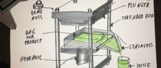
To make a homemade ornithopter flywheel with your own hands, you will need the following consumables:
In the picture below you can see drawings for making an ornithopter with your own hands.
For manufacturing, it is better to use linden or balsa; you can use carbon tubes or, as our Chinese comrades do, plastic rods. However, you can plan out the silt of any tree - birch, linden, etc.
The connection of the frame slats is made using a tongue-and-groove type and is wrapped with threads impregnated with glue.
The leading edges of the wings are also tied to the levers with threads, but before that a hole is made in them through which the lever spike is passed.
The bearing of the rubber motor shaft and levers can be made from wire insulation, or from parts of the rod from the handle; they are also wound with threads and the threads are impregnated with glue. A crankshaft similar to the one in the figure is bent from the wire, then a bead is put on it and it is inserted into the bearing, after which the hook is bent (see figure). The levers are bent and after they are inserted, their ends are bent.
The stabilizer tail is fastened from slats in the same way as the frame, after which wire is wound to it with threads and bent as in the photo.
A cut is made in the ornithopter frame into which the wire is inserted, after which it is wrapped with thread and glued.
Next, connecting rods are made, we make them from bamboo, it’s just convenient to break off thin sticks from it, we put tubes of wire insulation on their ends, we burn holes in the tubes, heat the wire over a candle and quickly pierce the tube with it. We make the tubes longer from the end where the stick is inserted; you will need this for adjustment.
We stretch two rubber bands between the hooks and twist the rubber motor, but not too much, and let go, the wings should begin to move, if their stroke is not the same, then bend the front crank.
Next, we lubricate the central rib and the edge slats with rubber glue, put our aircraft on the film and straighten it so that the film sags, but not much, we try to do it equally on both sides, otherwise it will fly in circles.
When using rubber cement, it is advisable to back everything up with small strips of tape.
We also make sure that the wings are identical.
Next we glue the stabilizer, preferably more tightly.
Be sure to let the glue dry and then launch!
If you don't quite understand the construction, watch the video below.
How a Moscow engineer built a flywheel (4 photos + 1 video)
An ancient dream, like our entire family, to fly like a bird - that is, freely flapping its wings - remains unfulfilled. This dream is so strong that although no airline or army in the world still operates a single ornithopter, the current Convention on International Civil Aviation includes its definition: “A heavier-than-air aircraft that is supported in flight primarily by the reactions of the air.” with its planes, which are given a swinging movement.”
From airplane to helicopter
However, the dream of flapping flight also has a practical side. The aerodynamic quality - the ratio of lift to drag, which determines flight efficiency - is exceptionally high in aircraft. But airplanes require expensive and complex airfields and large runways. Helicopters are more convenient in this sense; they take off and land vertically, without requiring any infrastructure. They are much more maneuverable and are even able to hover motionless. But the aerodynamic quality of helicopters is low, and an hour of their flight time is not cheap at all.
There are many attempts to cross one with the other - rotary-wing gyroplanes and tiltrotors have their fans. For solving some narrow tasks, these aircraft may even be indispensable. But still, such hybrids turn out to be not very successful: there is a well-known joke that they combine not so much the advantages as the key disadvantages of both airplanes and helicopters. But flywheels may be a suitable solution. Theoretically, they will be able to take off from a standstill, will be maneuverable up to the ability to hover in the air, and will be able to demonstrate almost aircraft-like aerodynamic quality.
But the first awkward balloonists thought, of course, not about airplanes, which did not exist yet, but about birds. It seemed that it was enough to learn to push off the air with wings - and the person would fly. With such views, of course, none of them were able to get off the ground. Winged mechanical devices made for clumsy gliding at best, as was done by the legendary Benedictine monk Aylmer, who jumped from the tower of Malmesbury Abbey in England about a thousand years ago, sustaining severe injuries.
Tiny ornithopters are being developed around the world. As a rule, their authors try to imitate nature with greater or less accuracy, repeating the design of a flying insect. In May 2015, Peter Abbeel and Robert Dudley from the Biomimetic Millisystems Laboratory at the University of Berkeley demonstrated a very impressive take-off of a 13.2-gram flywheel from a “launcher” on the back of a six-legged microrobot.
From bird to insect
The reason for the numerous failures is clear: the very essence of flight in those years was represented rather vaguely. What gives birds lift is not the support of the air, but the special contour of the wing profile. By dividing the oncoming flow in two, it causes the air above the upper edge to move faster than above the lower edge. According to Bernoulli's law, pressure will be higher in an area with slower flow. The resulting difference between the pressure under the wing and above it creates lift. But once you start flapping your wings, this clear picture changes completely.
A well-known saying says that “according to the laws of aerodynamics, bumblebees cannot fly at all.” In principle, this is true: from the point of view of classical aerodynamics, insects and their wings are something surreal. Even in theory, they are unable to create the lift and thrust necessary for flight - unless we move from classical glider aerodynamics to new, unsteady ones. Here everything is different: turbulent turbulence, with which aircraft designers struggle tirelessly, becomes the key to flight for both the bumblebee and its relatives.
How to set up an ornithopter
• If your bird is diving, bend its tail up; if it is pitching (raises its nose and falls), then lower it, on the contrary. Also, by changing the length of the connecting rods, we achieve greater stability and traction during flight.
• If everything is assembled correctly, this model gains altitude in a straight line, after which it slowly flaps its wings and then lands, slightly tucking its wings. The indoor model looks more like a dragonfly when it climbs, the flapping frequency reaches 20Hz. When assembling a larger model, the flight time, height and entertainment value of the flight increase, the frequency of swings decreases, but you need a more powerful and longer elastic band
However, flying on a rubber motor is not very exciting. Much more interesting is a radio-controlled ornithopter.
How to make an ornithopter with your own hands
This instructable is the story of how I made a prototype ornithopter.
For those who don't know, an ornithopter is a machine that flies by flapping its wings, just like a real bird. The idea was to build an ornithopter from scratch, control it remotely and, of course, make it fly.
Please do not judge strictly - I am not a professional aircraft modeller. So not everything works the way I would like, but it still works.
The real result can be seen in a multi-part video on our Youtube channel. If you like this tutorial, please subscribe to the channel.
The instructions will be corrected and improved with new materials over time, just like the Ornithopter.
From game to science
It must be said that if “useful” flapping flight has not yet been mastered, the gaming industry already feels quite confident in this area. The first small models with elastic bands appeared on sale at the end of the 19th century, and today one of the popular toys with flapping wings, an electric motor and radio control is offered by the toy robot developer company WowWee.
“I myself started with aircraft modeling,” says Andrey Melnik, “so I can imagine how demanding airplanes are for the skill of the pilot who controls them from the ground. Literally one awkward movement - and he falls into a tailspin or roll. And I can say that my experience in controlling our flywheel shows that even a child can handle this device. We have turned out to be so stable that it easily forgives all mistakes and remains in the air.”
People are reluctant to invest funds in the development of a new type of aircraft with rather dubious prospects. However, Andrey Melnik and Dmitry Shuvalov managed to convince investors that thanks to modern technologies and with the proper investments, a flywheel could be created. “We managed to find several fundamental points that had previously been misunderstood, including when I worked with Professor Kiselev,” adds the designer. — Our first models simply fell apart, unable to withstand the load. So, it was assumed that aerodynamic forces create such a load on the device. However, tests have shown that this is not the case, and the main impact is due to the inertia of the flapping wings.”
Having identified the reasons for the failures, the developers reduced the weight of the wing as much as possible - to 600 g with an area of 0.5 m 2 - and damped its impact on the fuselage. “A real surprise for us were the simulation results, which showed that the aerodynamic center of the four-wing aircraft is not somewhere between the front and rear pairs of wings, but behind them,” recalls Andrey Melnik. — To solve this problem, we had to change the geometry of the front and rear tails. But as a result, the flywheel began to confidently stay in the air.”
Selecting the initial parameters of wingspan, weight and flapping frequency.
How often do birds usually flap their wings?
I searched the Internet for existing ornithopter designs and analyzed their sizes. Most ornithopters are made in line of a certain size. Hobbie ornithopters can be sorted by wingspan (from 660 to 3000 mm) and weight in flight. My ornithopter, with a wingspan of 1200-1400 mm, would be somewhere in the middle of this scale, not big, but not small either.
Knowing the approximate flapping frequency (5 to 7 Hz), I can design the flapping mechanism.
As a result, I selected the following parameters for the ornithopter:
From Moscow to Toronto
These subtleties were not known for a long time and are still not fully understood. But it turned out that in the simplest case this is not necessary. Even before World War II, German aircraft designers successfully launched small, lightweight ornithopters using a twisted rubber band for drive. Even the famous aerodynamicist Alexander Lippisch paid tribute to their passion, and in the 1930s Eric von Holst managed to lift an ornithopter off the ground, on which an internal combustion engine was installed. However, it was not possible to create a device that could be considered as a prototype of something useful, capable of carrying at least one person or cargo. In the 1960s, Percival Spencer demonstrated the flight of an “orniplane” with a wingspan of 2.3 m and a tiny (5.7 cm3) two-stroke engine - it was piloted by an operator via cable.
A larger flywheel took off only in the early 1980s, when Valentin Kiselev, a professor at the Moscow Aviation Institute, designed a seven-kilogram device capable of taking off independently and remaining in flight. Over time, the model was freed from the cable and controlled via radio. Following in Kiselev’s footsteps in this work was his overseas colleague James Delorier. In 1991, Deslauriers received a diploma from the International Federation of Aeronautics for creating "the first powered and remotely controlled ornithopter." In 2006, his model UTIAS Ornithopter No. 1 took off, and soon the manned flywheel Snowbird also took off - in 14 seconds it flew about 300 m under the pilot’s muscular traction.
“This is not a completely fair result,” explains Professor Kiselev’s student, MAI graduate Andrei Melnik. “I am familiar with these structures, and they cannot be considered flywheels in the full sense of the word. The first device was equipped with a jet engine to create thrust and take off. And the second demonstrated another important thing: that human muscular strength is not enough for flapping flight. Even a trained pilot, an athlete, managed to fly only a short distance.”
Selecting a Swing Mechanism
The swinging mechanism is the most important part of the ornithopter. It converts electricity from the battery into flapping wing motion. Designing and assembling such a mechanism is quite a difficult task, since it must withstand enormous forces that change direction several times per second, and at the same time be extremely light and durable.
There are a large number of flapping mechanisms. Here are the most used ones.
Staggered Crank
The design of the crank is the most basic among swing mechanisms. The stepped shaft parts are at the required distance and angle to achieve a symmetrical swing. This is a commonly used design among hobbyists who assemble ornithopters from scrap materials.
Single Gear Crank
Although the single gear crank design looks simple, it is more complex than it appears. The center point where the connecting rod and wing hinges are connected to each other should expand and contract as the mechanism closes. Compression and expansion at very high frequencies can cause wear on the component.
Dual Gear Crank
This design has two gears that control the hinges of each wing separately. There are several transmission design options. The gear can drive both auxiliary gears. This way the secondary gears will rotate in the same direction as each other. In another design, the drive gear rotates a secondary gear, and that secondary gear rotates another secondary gear. The secondary gears will rotate counterclockwise towards each other. This design is much easier to implement and reduces wing misalignment.
Transverse Shaft
The transverse shaft design is another option for the crank mechanism. This design provides the most symmetrical swing possible. However, this is the heaviest and most complex design. The rotating gears and wings are not in the same plane, so the connecting rod must rotate. The connector rod has a ball bearing inside and this only adds weight to the component itself. The number of gears used in this design is more than in any other design. The cross shaft design is typically used for large ornithopters where the weight can be overcome by large wings.
I decided to go with a cross shaft design. The size of my ornithopter allows for the additional mass of the mechanism. In addition, such a design is easy to manufacture from sheet material, since the planes of the gears are parallel to the plane of the housing.
Theoretical implementation
Muscle-powered ornithopter
Edward Frost's ornithopter made of willow, silk and feathers, 1902.
According to various sources, the average maximum power a person can generate in the first 10 seconds is 1.85 liters. s., and with further operation for 1-2 minutes the power drops to 0.5 liters. With. The power required by the bird to fly is up to 0.02 liters. With. per kilogram of weight. Thus, a person is able to create a lifting force in the amount of (1.85 / 0.02) = 93 kg. However, the maximum power indicators can only be achieved by heavyweight athletes, whose weight exceeds the lifting force created, even without taking into account the weight of the aircraft. Theoretically, if a person weighing 75 kg were able to generate maximum power, he would be able to fly an ornithopter weighing 15 kg using only muscular traction, but such a flight would last no more than a few seconds.
As an option, the ideas of using spring, rubber, pneumatic and other batteries to accumulate energy generated by a person at moments of least load were also considered. The best results could be achieved by charging the battery before the flight begins. But in this case, such a device essentially becomes an ordinary engine with low efficiency. Similar batteries have found their use in small models of ornithopters. For example, one of the first free-flying models of unmanned ornithopters, created by Alphonse Penaud in 1872, uses a spin-on rubber as a motor.
Ornithopter glider
Due to the complexity of implementing a manned, motorless ornithopter as a self-sufficient aircraft, the idea of combining an ornithopter with a glider arose. The bottom line is that the device rises into the air with outside help (for example, towing, using a winch), and the propelling mechanism (wing flapping) is used to subsequently maintain the glider at a constant altitude during free flight. Such devices cannot be considered “real” ornithopters, since they are not capable of lifting off the ground on their own. The formula for calculating the power required to keep a glider in the air is as follows:
N = G ⋅ w 75 {\displaystyle N={\frac {G\cdot w}{75}}} , where
- G {\displaystyle G} — mass of the aircraft including the pilot, kg;
- w {\displaystyle w} — vehicle descent speed, m/sec.
| The information in this section is out of date. You can help the project by updating it and then removing this template. |
If we take the rate of descent equal to 0.45 m/sec and the power expended to be 0.6 hp. With. (even assuming 100% efficiency), then the weight of such a device together with the pilot should not exceed 100 kg. In this case, a person will not be able to maintain flight for a long time, since he also needs energy in order to control the glider itself.
Motorized ornithopter
| The information in this section is out of date. You can help the project by updating it and then removing this template. |
The construction of a manned motorized ornithopter should be an intermediate step on the way to a muscle-powered ornithopter, since this problem is solved in some ways easier - the designers are spared the intractable problem of a lack of human power. The main problem when building a motorized ornithopter comes down to the choice of motor to use.
A study of bird flight has shown that as a bird's size increases, the number of wing beats decreases. The approximate number of flapping strokes for a manned ornithopter would be approximately 50 flapping strokes per minute. Due to the need to transform rotational motion into translational motion and reduce high speeds, modern internal combustion engines are not the best suited for solving this problem. Even if you “remove” the internal combustion engine from the crankshaft, make it low-speed and transmit the translational movement of the pistons directly to the wing arms, then the problem of inertial forces that arise arises when trying to transfer the work of gas expansion during an explosion in a short period of time to move relatively large massive wings .
At the same time, for example, a steam engine, which allows you to regulate the speed and smoothness of the movement of the pistons, would be much better suited for transferring energy to flapping wings. The very task of building an ornithopter in this case comes down to designing the engine and its components (boiler with firebox, condenser, etc.) in accordance with the aerodynamics and kinematics of the aircraft.
Orthopter
The very idea of an ornithopter—a bird-winged aircraft—implies imitation of natural prototypes, birds and insects, both in the shape of wings and in their movements.
Orthopter "Grey Goose" 1927.
However, some inventors, in attempts to create a manned vehicle powered by muscular propulsion, came up with rather intricate solutions, such as louvered wings, trying to surpass the natural solution with a technical approach.
One of the most common types of non-bird-like flapping devices is the orthopter (English orthopter, from the ancient Greek ορθός - straight and πτερόν - wing; “straight-winged”) - an aircraft that uses a direct “blow” with the plane of the wing during flapping to obtain lift. down.
Selection of components. Motor, ESC and Battery.
Motor selection
The motor must be small. Large motors have a lot of weight, which is very critical for the design. At the same time, the electric motor must be robust to provide sufficient torque to overcome air resistance.
To increase the torque and achieve the required swing frequency, I am going to use a gearbox. In this case, I can take a weaker engine with a higher number of revolutions per minute (RPM).
I chose this motor:
It can be replaced with:
Pay attention to an important detail. You need an outrunner. The motor mounting holes must be on the same side as the output shaft. Thus, the housing, which is located next to the output shaft, must be stationary.
Main engine characteristics:
Brief explanation of the name:
Power supply
I use a Li-Po battery to power the motor. The capacity-to-weight ratio of such batteries is quite high. In addition, they are capable of delivering the high current required by brushless motors.
There is a noticeable difference in weight between 2 and 3 cell batteries of the same capacity. So I think it's better to use a 2 cell battery.
Main characteristics of the battery:
Let's check if the maximum battery current is sufficient.
By multiplying the discharge rate by the capacity, you can calculate the maximum current value that the battery can produce:
The maximum current of 27A is higher than what the motor can draw (22A), so everything is fine. Battery capacity is also very important. This parameter affects the flight duration of the ornithopter.
However, in my case, it is much more important to choose a battery based on weight.
Speed controller (ESC)
Source
From practice to theory
The first flight of the flywheel took place in 2012, when the device, still almost uncontrollable, flew about 100 m. Its rigid composite wings were driven by a small engine with a crank transmission. And after another six months, the improved 29-kilogram version remained in the air for as long as a half-liter fuel tank lasted - 10-15 minutes. The developers have issued RF patent No. 2488525 for their flywheel.
“Among other things, we also faced a management problem,” continues Andrey Melnik. — Vertically, the flywheel was deflected and controlled reliably, using the elevators on the tail. But in order to change course horizontally, we had to install additional winglets on the wings. By changing their position, it became possible to fully control the device in flight via a radio channel.”
It must be said that the flywheel still does not take off vertically, although it requires a very short runway for takeoff. Just 5-10 m - and he goes into the lead. This figure can be further reduced, but to create a real full-size model, the design will have to be seriously improved. According to Andrey Melnik, first of all it is necessary to abandon the crank mechanism, which is not very successful for creating flapping movements of the wings. It generates too dangerous inertial forces, which are especially strong at the upper and lower “dead points” of the oscillation. “If we take another drive that is capable of storing the energy of the last phases of movement and then using it to move in the opposite direction, it will be much more efficient,” says the designer. “This could be, for example, a pneumatic mechanism, we have such ideas.”
“The worst thing is that we still don’t understand exactly how it flies,” continues Andrei Melnik. — Both by education and skills, we are practitioners, designers, not theorists, not scientists. But we can definitely say that conventional theoretical models are not suitable for a flywheel, and our tests confirmed this. In particular, our lift coefficient turned out to be many times greater than that of a typical aircraft wing. Why? I hope someone can figure it out." Perhaps everything will really happen in the reverse order: having figured out how the flyer flies, we will finally understand the flapping flight of birds and insects.
Source
How to set up an ornithopter
• If your bird is diving, bend its tail up; if it is pitching (raises its nose and falls), then lower it, on the contrary. Also, by changing the length of the connecting rods, we achieve greater stability and traction during flight.
• If everything is assembled correctly, this model gains altitude in a straight line, after which it slowly flaps its wings and then lands, slightly tucking its wings. The indoor model looks more like a dragonfly when it climbs, the flapping frequency reaches 20Hz. When assembling a larger model, the flight time, height and entertainment value of the flight increase, the frequency of swings decreases, but you need a more powerful and longer elastic band