How to make a walkie-talkie
If you are tired of endless bills for mobile communications and want to switch to the “Free” tariff, if you dream of making your own radio station for the boys in the area, or just want to maintain the anonymity of conversations at a distance of up to one and a half kilometers, then the diagram below for a simple homemade walkie-talkie with your own hands just for you.
How to make a homemade walkie-talkie?
Making a simple walkie-talkie with your own hands is much more difficult than buying a ready-made version in a store, but who knows where an extreme situation will find you, suddenly it will be a disaster of transport, by a lucky chance carrying:
3 transistors P416B, 4 transistors MP42
Resistors for 3K, 160K and 4.7K 2 pieces each, 22K, 36K, 100K, 120K and 270K 1 piece each and as many as 6 resistors of the 6.8K type
Capacitors type 10MK*10V, 3300, 1000, 100, 6, 5-20 2 pieces each, 22, 10 and 0.047MK 1 piece each and as many as 4 capacitors type 5MK*10V
and
antenna, microphone, speaker, switch, switch, DC source, 2 PCB boards, connecting wires and wire with a diameter of 0.5 and 0.1 mm
multiplied by the number of homemade walkie-talkies that you are going to make with your own hands.
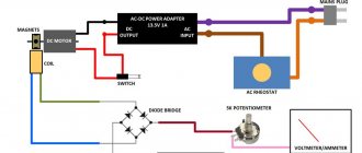
Diagram of a simple homemade walkie-talkie:
where A1 is one common antenna for sending and receiving a signal, SA1 is a power switch, and switch SA2 will connect a homemade radio station to a current source: while sending a signal to the transmitter, and accordingly to the receiver while receiving.
The following figure clearly shows the winding diagram of the coils, the basis for which will be plexiglass, polystyrene or, in extreme cases, cardboard cylinders with a diameter of 0.8 cm and a height of 2 cm, and as a winding - 1 layer of copper wire with a diameter of 0.5 mm, laid in what is called turn to turn . Coils L5 and L1 of your simple homemade walkie-talkie with your own hands should have ten turns each, coil L2 should consist of four turns and is located between the halves of winding L3, consisting of eight turns and having a wire tap in the middle. For those who don’t understand simple radio circuits with their own hands, coils L3 and L2 are wound on the same base.
L4 and L6 are a 200-turn winding of 0.1 mm wire around a housing of MLT-0.5 type resistors with a minimum resistance of 1 MOhm.
If you have read to these lines, then you probably understand at least something about electrical engineering, and therefore place the parts on textolite boards (one of them will be with a master oscillator, and the other with a low-frequency amplifier and receiver) on one side and connect them on on the other side with an insulated wire with a diameter of 0.2-0.3 mm, it should not be difficult for you, as well as connecting the batteries using a stranded wire insulated with vinyl chloride. You can make a printed circuit if you have a foil getinax, and the frame of your simple homemade walkie-talkie can be done with centimeter-long scraps of copper wire driven into holes with a diameter of one millimeter.
It remains to make sure that the windings of the chokes and coils are mutually perpendicular, the handle of the capacitor C15 is located on the front panel of the radio station, and the master oscillator is separated from other parts of your simple homemade walkie-talkie with your own hands by a tin screen, which in turn is connected to the “+” power supply.
The absence of a microphone can be successfully corrected by having a pair of high-impedance headphones, and instead of a telescopic antenna from a radio, you can use a meter-long brass tube with a diameter of 0.5 cm.
Setting up and debugging a homemade walkie-talkie
Even if you regularly attended all the classes of the circle of young radio amateurs, it is not a fact that your simple do-it-yourself walkie-talkie will immediately work as it should.
Debugging a homemade walkie-talkie begins with improving the quality of signal reception, for which replace R10 with a variable resistor of 33-47 kOhm and wait until the noise becomes as loud as possible. Now change the level of inductance L5 with a tuning core, achieving better signal quality, and finally change the variable resistor back to a constant one with the desired resistance.
If the timbre of your voice is greatly distorted when transmitting a signal, select resistors R1 and R3 more carefully, and to debug the generator and antenna, assemble a wave meter, the electronic circuit of which is shown below. The basis for a coil L of ten turns of 1.2 mm wire will be a frame with a diameter of 2.2 cm, where the third turn from the bottom is a tap. Capacitor C1 needs to be made tuning, with an air dielectric, and its handle should be placed opposite the current frequency of the signal transmitter of your homemade walkie-talkie, making sure that its coil L3 is located next to the L coil of the wave meter, thereby making it a kind of indicator. Now, instead of C9, trying capacitors of different capacities, you need to achieve the maximum deviation of the needle on the wavemeter division scale, and, bringing the latter directly to the antenna itself and rotating the tuning core L1, adjust the antenna to the resonance frequency of the circuit L3C8C9 until the needle on the wavemeter scale shows the maximum deviation.
How to make a radio station with your own hands
You can download free circuit diagrams for making many types of receivers and transmitters yourself at home, from a homemade radio station to radios and walkie-talkies of various types >.
How to make an antenna for a walkie-talkie
If you are the owner of a walkie-talkie, then it will be no secret to you that homemade antennas for these devices are more effective than factory ones. The size of the homemade product, by the way, can be set within 9-25 cm. You will need:
- connector suitable for your walkie-talkie;
- a piece of any thick cable (only insulation is needed from it);
- PEV wire 0.25-0.7 mm;
- heat shrink;
- glue.
The manufacturing process looks like this:
- Pull all contents out of the cable without damaging the outer tube of insulating material.
- At this stage, check how well this tube fits into the connector - ideally it should fit into it.
- On the tube, 4-5 mm away from the level of the connector, you need to make a hole for the wire, where the latter should be placed - inside the pipe.
- Solder the central pin of the connector to the end of the wire, and then glue the tube into the last one.
- The PEV wire protruding from the tube should be wound in equal turns from the connector outward. The winding length is 10-25 cm. The thicker the cable, the longer the winding.
- Secure the skeins with glue to prevent them from unwinding.
- Test the device and trim the winding if necessary.
Algorithm for creating a 50 MHz walkie-talkie
If you purchased a ready-made kit for creating a walkie-talkie with your own hands, you will need the following diagram. The names of the elements must be indicated on your board and diagram attached to the device for making a simple walkie-talkie.
First, start installing resistors and forming the electrodes of this element. Using a soldering iron, the resistor must be soldered to the board, and the protruding electrodes must be cut off with wire cutters. Carefully and carefully install all components, relying on the drawn outline on the board.
Start soldering the extension coil L 1, and then the capacitors. The next step is to solder the electrolytic capacitors. Since they have a certain polarity, it is necessary to properly fit the negative electrode into the board.
Using a soldering iron, attach the contour coil T 1 and the body of the switching element S 1. Proceed to soldering the transistors, relying on the contour drawn on the board. You need to solder the cut parts of the electrodes remaining from step 1 to the board. Do this so that jumpers J 1 are formed.
Now you can check the quality of the work performed. If necessary, wipe the board with an alcohol solution, and later install the on/off button. Attach the finished board to the case using self-tapping screws.
Now you can install one of the main elements of the walkie-talkie - the antenna. On top of it there should be a small plastic cap, on the other side you need to solder a conductor that will connect the antenna to the board. Using the remaining pieces from the conductors, attach the S 2 switch to the board and check its functionality.
Place the terminals in the battery compartment. Now you need to solder the conductors responsible for the speaker and power supply system. If you have no doubt that you did everything correctly, connect a battery to the mechanism and check it. The finished device should make a hissing sound.
Assemble the second radio in the same way as the first. To ensure that the devices operate with the same cleanliness, remove one board from the fastener. We hope that these detailed instructions for creating a walkie-talkie with your own hands helped you understand the creation of this mechanism.
How to make an antenna for a walkie-talkie
If you are the owner of a walkie-talkie, then it will be no secret to you that homemade antennas for these devices are more effective than factory ones. The size of the homemade product, by the way, can be set within 9-25 cm. You will need:
- connector suitable for your walkie-talkie;
- a piece of any thick cable (only insulation is needed from it);
- PEV wire 0.25-0.7 mm;
- heat shrink;
- glue.
The manufacturing process looks like this:
- Pull all contents out of the cable without damaging the outer tube of insulating material.
- At this stage, check how well this tube fits into the connector - ideally it should fit into it.
- On the tube, 4-5 mm away from the level of the connector, you need to make a hole for the wire, where the latter should be placed - inside the pipe.
- Solder the central pin of the connector to the end of the wire, and then glue the tube into the last one.
- The PEV wire protruding from the tube should be wound in equal turns from the connector outward. The winding length is 10-25 cm. The thicker the cable, the longer the winding.
- Secure the skeins with glue to prevent them from unwinding.
- Test the device and trim the winding if necessary.
Zello-walkie-talkie application
The most convenient and easiest way to experience the beauty of talking on a walkie-talkie is to install an application with this function on your smartphone. The leader among them is Zello, which can also be installed on a laptop or PC. The program is completely free for all existing operating systems. Zello is often used by mobile software developers - it allows them to add the function of communicating via walkie-talkie to their applications.
Zello uses Wi-Fi or mobile Internet to transmit voice. The application also supports Bluetooth headset. Your voice message is first saved by the system and then sent to the recipient. Zello supports communication between 800 interlocutors, displays their connection status, stores voice message histories, and creates special password-protected channels.
Voxer walkie-talkie
Another way to answer the question “How to make a walkie-talkie from a smartphone?” is a Voxer application, absolutely free for iPhone and Android owners. Transferring data via mobile Internet or Wi-Fi will also not bring you additional waste. The application can be called a walkie-talkie conditionally - it does not provide the ability to talk in real time, but quickly sends voice messages from user to user.
Some of the features of this walkie talkie app include the following:
- The ability to record a voice message and save it inside the program at times when the gadget is not connected to the Internet.
- Reproduction of the interlocutor's voice in two or three times acceleration.
- Storing the history of voice messages.
- Ability to indicate your location to your interlocutors.
- In addition to the walkie-talkie mode, this application can be used as a convenient messenger - through it you can send text messages, video, audio or photos.
A similar app to Voxer would be HeyTell. It is also absolutely free and works in all data transfer modes. It is distinguished by more flexible settings and the presence of three privacy categories for your conversations.
DIY stereo transmitter circuit diagram
The scheme is simple, especially if you understand its operation. I suggest you immediately visually divide it into the left side with one transistor and the right side with two transistors. The transistor VT1 assembles a transmitter and a receiver at the same time. When the switch closes contacts “1”, the radio is in receive mode and this transistor operates in supergenerative detector mode. And when the contacts close to mode “2”, this is transmission and the transistor works as a master oscillator. With this, I think it’s clear. A simple low-frequency amplifier is assembled on transistor VT2, VT3, which, depending on the position of the switch, either amplifies the signal from the microphone and transmits it to the transmitter, or amplifies the signal from the supergenerative detector and transmits it to the loudspeaker. By the way, the loudspeaker and microphone are one and the same element - a high-impedance DEM telephone capsule. Coil L1 is wound on a frame with a diameter of 8 mm with a ferrite core turn to turn and has 9 turns of PEL wire with a diameter of 0.5 mm. Coil L2 is wound on top of coil L1 and has 3 turns of the same wire. Coil L3 has a diameter of 5 mm and contains 60 turns of PEL wire with a diameter of 0.5 mm. As an inductor L4, you can use the primary winding of the output transformer of a transistor receiver. The antenna was made by me from a thick aluminum wire, with a piece of insulation, on top of which the L3 coil was wound. I made such a walkie-talkie back in school, but then I already changed all the transistors to more modern ones with high gain. For example, I replaced VT1, VT2 with KT361, and VT3 with KT315. Now I would, of course, change the power polarity and the polarity of the capacitors, replace all transistors from the npn structure to pnp, and pnp to npn. Well, I would install modern transistors. There are no particular requirements for transistors, so absolutely any will do. The author of the diagram says that the range of action of radiums of the same type in open areas is 100-200 meters. I accelerated such radios to 500 meters, for this I used modern transistors, increased the antenna to 900 mm, plus increased the generator current by replacing the 100 Ohm resistor with a 50 Ohm one. Someone will say that it’s all due to the enlargement of the antenna, with which I disagree and will say that with the “native” antenna I was able to communicate over 300 meters. If you assembled the walkie-talkie correctly and from serviceable parts, then the whole setup will come down to tuning coil L1 at a frequency of 27 MHz. This can be done with a subline core or a capacitor in the circuit.
Schematic diagram
Figure 1 shows a diagram of a type “D” radio station with a communication range of at least 80 m. The transmitter and receiver use the same RF stage on transistor VT1. When receiving, it operates in super-regeneration mode, and when transmitting, in continuous generation mode with quartz frequency stabilization and collector modulation.
Let's consider separately the operating modes of the radio station. In the receiving mode, the signal received by the antenna WA1 through the extension coil L1 and the anti-parasitic resistor R1 is supplied to the coupling coil L2 of the super-regenerative detector - transistor VT1.
For direct current, the transistor mode is set by the base divider R6, R8 and resistors R4 and R2, which, together with capacitors C5 and C2, set the quenching frequency. Circuit elements L3 and C1 adjust the detector to the required frequency. The electrical circuit, consisting of SZ, R3 and C7, sets a deep positive feedback.
During a flash, due to an increase in the collector current of transistor VT1, C2 is slightly discharged, and C5 is recharged. This leads to a decrease in the current VI and disruption of generation. After this, through resistors R2 and R4, C2 and C5 are recharged, respectively.
Rice. 1. Schematic diagram of a small-sized radio station.
Recharging occurs until the collector current VI reaches the value at which the next flash is formed. Oscillograms at characteristic points of the receiver are shown in Figure 2. From capacitor C2, the detected signal, together with a sawtooth damping signal, goes through capacitor C4 to the volume control R3.
Next, the signal passes through a low-frequency filter assembled at R14, СІЗ, С14, which cuts the blanking frequency, the useful audio frequency signal is sent to the ultrasonic sounder. The AF amplifier is assembled on two transistors VT2 and VT3. The output stage operates in class A with a collector current of about 20 mA. The dynamic head BAI is included in the final stage of the ultrasonic sound amplifier through the output transformer T1.
In transmission mode, the collector current VT1 increases, because its base bias is determined by resistor R7, and the positive feedback loop is closed through C7, ZQ1 and C8. Power is supplied to the collector VT1 through the secondary winding of transformer T1.
Rice. 2. Oscillograms at characteristic points of the receiver and transmitter.
In this case, the VTI transistor goes into stable generation mode with quartz frequency stabilization. The dynamic head BAI is connected to the base VTZ through resistor R15.
With this inclusion of VA1, it is possible to obtain an amplitude of the low-frequency voltage on the collector VT2 of 1.2 V, which is sufficient for effective modulation of the high-frequency signal generated by the transmitter on VT1.
The SA2 button is used to transmit a call signal or Morse code. When you press the button, the ultrasonic sounder is excited at a frequency of 1000 Hz. In Fig. 13.4.c shows oscillograms at characteristic points of the transmitter.
Antenna
The next stage is creating and configuring the antenna. Let's look at how to make an antenna for a walkie-talkie. So, after the radio body is assembled, you will need to make exactly 11 turns of wire with a thickness of 0.5 mm for the L1 coil. This uses a range setting of 27-30 MHz. If precise adjustment of the range is needed, then it is necessary to use tuning capacitors C1 when receiving data, as well as C2 when transmitting data. In addition, the reception mode of switch SA1 should be taken into account. The range should be adjusted using a factory-made control receiver. You can simplify this task by taking out your headphones, so the setup will be much faster.
So, what do you need to make a walkie-talkie?
To create a walkie-talkie you will need the following items:
- 4 MP-42 transistors and 3 P416B transistors;
- Resistors. You will need a lot of them: two pieces each. 3K, 160K, 4.7K, one each – 22K, 36K, 100K, 120K, 270K, and six pcs. 6.8 K;
- Capacitors: two 10 MK 10 V, 3300, 1000, 100, 6, 5-20, 22, 10 and one 5 MK 10 V – 4; 0, 0, 47 MK.
- Telescopic antenna;
- Microphones and speakers;
- Textolite boards - 2 pcs.
- Soldering iron;
- Socket;
- Wire cutters.
Almost all of the above is included in the special kit for radio amateurs JC986A. The further algorithm will be based on this set.
It is worth considering that creating your own walkie-talkie requires skills in working with a soldering iron and knowledge of how to determine the values of the elements.
How to assemble a simple radio receiver?
There are several radio receiver circuits:
- detector;
- direct amplification;
- (super) heterodyne;
- on a frequency synthesizer.
Receivers with double and triple conversion (2 or 3 local oscillators in a circuit) are used for professional work at the maximum permissible, ultra-long distances.
The downside of the detector receiver is low selectivity: signals from several radio stations can be heard simultaneously. The advantage is that there is no separate power supply: the energy of the incoming radio waves is enough to listen to the air without powering the entire circuit. At least one repeater must be broadcasting in your area - in the range of long (148-375 kilohertz) or medium (530-1710 kHz) frequencies. When you are 300 km or more away from it, you are unlikely to hear anything. It should be quiet around - it is better to listen to the program using headphones with high (hundreds and thousands of ohms) impedance. The sound will be barely audible, but both speech and music will be understandable.
The detector receiver is assembled as follows. The oscillating circuit consists of a variable capacitor and a coil. One end of it is connected to an external antenna. Grounding is supplied through the building circuit, and the heating network pipes are supplied to the other end of the circuit. Any RF diode is connected in series with the circuit - it will isolate the audio component from the RF signal. A capacitor is connected to the resulting assembly in parallel - it will smooth out the ripples. To extract sound information, a capsule is used - the resistance of its winding is at least 600 Ohms.
If you disconnect the earphone from the DP and send a signal to a simple audio amplifier, then the detector receiver will become a direct amplification receiver. By connecting a MF or LW radio frequency amplifier to the input - to the circuit - you will increase the sensitivity. You can move up to 1000 km from the AM repeater. A receiver with a simple diode detector does not work on the (U) HF band.
To improve adjacent channel selectivity, replace the detector diode with a more efficient circuit.
To ensure selectivity in the adjacent channel, a local oscillator, a mixer and an additional amplifier are needed. A local oscillator is a local oscillator with a variable circuit. The heterodyne receiver circuit works as follows.
- The signal comes from the antenna to a radio frequency amplifier (RFA).
- The amplified RF signal passes through a mixer. The local oscillator signal is superimposed on it. A mixer is a frequency subtractor: the local oscillator value is subtracted from the input signal value. For example, to receive a station on 106.2 MHz in the FM band, the local oscillator frequency must be 95.5 MHz (10.7 remains for further processing). The value 10.7 is constant - the mixer and local oscillator are adjusted synchronously. Mismatch of this functional unit will immediately lead to the inoperability of the entire circuit.
- The resulting intermediate frequency (IF) of 10.7 MHz enters the IF unit. The amplifier itself performs the function of a selector: its bandpass filter cuts the spectrum of the radio signal to a band of only 50-100 kHz. This ensures selectivity on the adjacent channel: in the densely packed FM range of a large city, radio stations are located every 300-500 kHz.
- Amplified IF is a signal that is ready to be transferred from the radio frequency region to the audio frequency region. The amplitude detector converts the AM signal into audio, highlighting the low-frequency envelope of the radio signal.
- The resulting sound signal is sent to a low-frequency amplifier (LF) - and then to a speaker (or headphones).
The advantage of the (super) heterodyne receiver circuit is satisfactory sensitivity. You can move tens of kilometers away from the FM transmitter. Selectivity on the adjacent channel will allow you to listen to the radio station you like, and not to the simultaneous cacophony of several radio broadcasts. The disadvantage is that the entire circuit requires power - several volts and up to tens of milliamps of DC.
There is also selectivity along the mirror channel. For AM receivers (LW, MW, HF bands) the IF is 465 kHz. If in the CB range the receiver is tuned to a frequency of 1551 kHz, then it will “catch” the same frequency at 621 kHz. The mirror frequency is equal to twice the IF value subtracted from the transmitter frequency. For FM (FM) receivers operating in the VHF band (66-108 MHz), the IF is 10.7 MHz.
Thus, a signal from an aviation radio (“mosquito”) operating at 121.5 megahertz will be received when the receiver is tuned to 100.1 MHz (minus 21.4 MHz). To eliminate the reception of interference in the form of a “mirror” frequency, an input circuit is connected between the RF amplifier and the antenna - one or more oscillating circuits (a coil and a capacitor connected in parallel). The disadvantage of a multi-circuit input circuit is a decrease in sensitivity, and with it the reception range, which requires connecting an antenna with an additional amplifier.
The FM receiver is equipped with a special cascade that converts FM into AM waves.
The disadvantage of heterodyne receivers is that the signal from the local oscillator without an input circuit and in the presence of RF feedback enters the antenna and is re-radiated into the air. If you turn on two such receivers, tune them to the same radio station, and place them side by side, close together, a slight whistling of a changing tone will appear in the speakers of both. In a circuit based on a frequency synthesizer, a local oscillator is not used.
In FM stereo receivers, after the amplifier and detector, there is a stereo decoder. Stereo signal encoding at the transmitter and decoding at the receiver is carried out using pilot-tone technology. After the stereo decoder, a stereo amplifier and two speakers are installed (one for each channel).
Receivers that do not have stereo decoding function receive stereo broadcasts in monaural mode.
To assemble the receiver electronics, do the following.
- Drill holes in the workpiece for the radio board, checking the drawings (topology, arrangement of elements).
- Place radio elements.
- Wind the loop coils and magnetic antenna. Place them according to the diagram.
- Draw the tracks on the board, checking the topology from the drawing. Paths are made both by cutting and etching.
- Solder the parts onto the board. Check the correct installation.
- Solder wires to the antenna input, power supply and speaker output.
- Install controls and switches. A multi-range model will require a multi-position switch.
- Connect the speaker and antenna. Turn on the power supply.
- The noise of an untuned receiver will appear in the speaker. Turn the tuning knob. Tune to one of the available stations. The sound of the radio signal should be free of wheezing and noise. Connect an external antenna. You need to adjust the coils and shift the range. Choke coils are adjusted by rotating the core, frameless coils are adjusted by stretching and compressing the turns. They require a dielectric screwdriver.
- Select an extreme frequency on the FM modulator (for example, 108 MHz) and move the turns of the local dyne coil (it is located next to the variable capacitor) so that the upper end of the receiver range stably receives the modulator signal.
Assemble the body:
- Mark and cut plywood or plastic into 6 edges of the future body.
- Mark and drill holes for the corners.
- Cut out a large round gap for the speaker.
- From the top and/or side, cut out slots for the volume control, power switch, band switch, antenna and frequency control knob, guided by the assembly drawing.
- Install the radio board on one of the walls using “pile” type screw racks. Align the controls with the technological holes on the adjacent sides of the housing.
- Mount the power supply - or USB board with lithium-ion battery (for the mini radio) - away from the main board.
- Connect the radio board to the power supply board (or to the USB controller and battery).
- Connect and secure the magnetic antenna for AM and the telescopic antenna for FM. Securely insulate all wire connections.
- If a loudspeaker model is being manufactured, install the speaker on the front edge of the case.
- Using the corners, connect all the edges of the body to each other.
For the scale, calibrate the adjustment knob and place a mark in the form of an arrow next to it on the body. Install an LED for illumination.
8 photos
Recommendations for Beginners
- To avoid overheating diodes, transistors and microcircuits, do not use a soldering iron with a power of more than 30 watts without flux.
- Do not expose the receiver to precipitation, fog, frost, or acid fumes.
- Do not touch the high voltage terminals of the power supply when the device under test is energized.
Don't part with your loved ones or new life for old things
Unfortunately, there are hundreds and thousands of such and similar cases. The small (up to 1,000 rubles) cost of such devices suggests that the owner will replace such a phone without regret, since the profitability of the repair will outweigh the cost of the product itself.
Nevertheless, such “lame ducks” - radiotelephones with minor breakdowns, are quite suitable for breathing new life into them with the hands of a radio amateur. For example, it is not at all difficult to make a remote signaling device for opening the front door out of a “toy”.
You can go even further and teach the “lame duck” to notify with sound about any other change in the controlled space within the apartment or office. The main thing is that the transmitting and receiving paths are working properly, and the “handset search” function is working. Next, I will tell you how to turn such a semi-functional wireless kit into a useful household item.
iPTT - walkie-talkie for iOS
Even a small child can figure out how to make a walkie-talkie on an iPhone or iPad using this application - it’s so easy to use. By the way, iPTT is the first application of its kind in the AppStore, and it’s completely free.
Using this program, you can create a direct communication channel with both an individual recipient and a group of people. You can also select the “whisper” mode - confidentially communicate with one person from the group.
An application similar in functionality to iPTT will be TiKL Touch Talk Walkie Talkie. It is available for free not only for gadgets on iOS, but also on Android.
Debugging a homemade walkie-talkie
Even if you carefully followed the specified algorithm, the equipment may not work properly. In order to adjust the operation of the mechanism, use a variable resistor and wait for the maximum volume of the hiss of the radio.
Using a tuning core, change the inductance level until the signal is correct. After this, do not forget to return the original resistor and adjust its resistance.
If your voice emitted by the second walkie-talkie is severely distorted, select other resistors and start creating a wave meter, the diagram of which you can find on the Internet along with photos of homemade walkie-talkies. By the way, you need to check the quality of communication at a distance of 5, then 10 and 20 meters; it is better to do this in an open space.
We have described a step-by-step algorithm on how to make a walkie-talkie with your own hands. It should help you create your own mechanism to ensure communication with family or friends during a hike, tourism, fishing or contact with a child.
Remember to take precautions when operating this equipment to avoid the risk of injury such as burns or electric shock.
Settings
If you assembled the radio correctly and from serviceable parts, then the entire setup will come down to setting the L1 coil to a frequency of 27 MHz. This can be done with a subline core or a capacitor in the circuit. One of the most popular amateur radio designs is the pocket radio. Of course, in our era of the total proliferation of mobile phones and pagers, the manufacture of homemade communication equipment has lost its relevance. However, in some cases, an FM radio may be indispensable, since it works regardless of the coverage of cellular stations. And the money in the account tends to run out at the most inopportune moment - for example, when listening to a room for a long time. This is where our simple, proven FM radio, based on a 4-transistor transmitter and receiver at a frequency of 100-105 MHz, comes in handy. Recently this design was published on our friendly website, but now we present the circuits in good quality, translated into Lay format by our respected comrade Alex1. The figures below show a diagram of the receiving and transmitting parts of the radio station, respectively. Winding data of coils and chokes: receiving L1 and L2, 8 turns of PEV0.6 each on a 4mm mandrel. Transmitting - 10 turns with a tap from the middle at a diameter of 4 mm. The chokes are 5-10 µH each, they are wound on 0.25-watt resistors 100-500 Ohms with a 0.2 mm wire in the amount of 50 turns. The verified version can be downloaded in the archive.
The FM band was not chosen by chance. It will be easiest for beginning radio amateurs to work with it, since the transmitter can be set up using a regular FM broadcast receiver. And after setting up the transmitter, we ensure that the receiving unit is operational. Also suitable for this is listening to FM radio broadcasting stations 88-108 MHz. Only after this you need to increase the frequency to 110-120 MHz to prevent accidental listening to your conversations on other receivers.
The operation of the units has no special features, and any “bug builder” with little experience will be able to run them without problems. The radio is powered by a 9-12V battery. Moreover, power supply from a stationary power supply is possible. This will turn it into a broadcast radio station (remember about the power limitation, according to the law). Well, the RX part works great as an FM radio receiver, which makes it possible to simply listen to music with it :)
Articles and Lifehacks
A smartphone is a multifunctional phone, the capabilities of which go far beyond “just making a call,” so the question is how to make a walkie-talkie from a phone
, we can solve it today thanks to many applications. It would seem, why make a walkie-talkie out of a fully functional phone if you can’t use other features in this mode? But this device has a number of advantages:
Ability to communicate with many people at the same time; - a closed communication channel that is completely inaccessible for listening; — no tariffs for call duration, etc.
Of course, in ra mode
Types of programs that turn a phone into a walkie-talkie
There are many mobile applications that allow you to simulate the operation of walkie-talkies. Some of them are very popular and have many advantages, others are less interesting, but are attractive due to their ease of use or lack of fees. So, first of all, programs distinguish between paid and free.
The former, as a rule, pay the operator, while the latter work for free via mobile Internet or Wi-Fi. Another important difference is the platform on which the application runs. Most are written for Android and iOS, but there are also those that work on the old Symbian, and there are even walkie-talkies that are provided by telecom operators, so they will be useful for any phone model.
Which program to choose to turn your phone into a walkie-talkie
To make a walkie-talkie from a phone, it is important to understand not the principle of implementing this process, but which program to choose. So, if your smartphone runs Android and iOS, you can choose between Zello and Voxer. The first allows 800 devices to work simultaneously (for comfortable use, it is better to reduce the number to three hundred), connecting via the Internet, you can also use it from a tablet and PC. It is also compatible with Bluetooth headsets, has high channel protection and other properties. The second can already unite only 100 people via the Internet and is used only on phones. But it already transmits photos and other media, allows you to save recordings, use it offline and then send it over the network.
For Symbian, Walkietooth and Push-To-Talk are recommended. The first one is quite old, but works offline. It unites only two people, and the message can only be 10 seconds long, but this is an indispensable option in conditions where there is no connection. The second one already uses the Internet and is more interesting in terms of functions.
Thus, a mobile walkie talkie is a very useful feature that can be used and relevant today.
Even though in our age of portable gadgets, walkie-talkies are not so relevant, it is still sometimes interesting, and sometimes necessary, to use them. Here we will look at how to make the simplest models of these devices, as well as related issues related to them.
In addition
In connection with the increasing use in everyday life of a large number of a wide variety of radio-electronic equipment that have sources of electromagnetic radiation, several resolutions have been adopted in Russia on this issue.
In particular, “Special conditions for the acquisition of radio-electronic equipment and high-frequency devices” (approved by Decree of the Government of the Russian Federation on July 17, 1996 No. 832), the Federal Law “On Communications”, etc. In accordance with the current legislation, for the purchase of radio-emitting devices it is necessary to obtain permission from the State Supervision for communications in the Russian Federation (main department or its territorial bodies).
For household equipment that explicitly contains radio transmitting devices, it is not necessary to obtain permits only for cordless telephones operating in the frequency bands 814.815 MHz, and 904.905 MHz with a power of no more than 10 mW for children's radio intercoms and radio-controlled toys operating in frequency band 26975. 27283 kHz with a radiation power of no more than 10 mW.
Since 1994, in the 27 MHz range (personal communications range), it is allowed to use the 26970. 27860 kHz frequency band for individual citizens and legal entities for the development, mass production, purchase and operation of radio stations with a radiation power of no more than 10 W. To operate at these frequencies, Glavgossvyaznadzor issues a permit using a simplified procedure.
Literature: V.M. Pestrikov. Encyclopedia of amateur radio.
Necessary first steps before opening
The first thing to start with is completing the necessary documentation. First of all, you need to open a legal entity, for example, a company, the charter of which will indicate the following types of activities:
- creation of television and radio projects;
- advertising of a commercial and political nature;
- television and radio broadcasting;
- activities related to the media;
- the possibility of purchasing studio space for radio stations and various facilities used for radio broadcasting.
Photos of walkie-talkies with your own hands
Modern element base makes it possible to create radio-electronic devices with excellent technical characteristics, minimal dimensions and low power consumption.
Of course, for radio amateurs living far from large cities and regional centers, the possibility of purchasing foreign integrated circuits is practically unrealistic, even though they are relatively inexpensive. However, this does not mean that the design of devices using modern ICs should be stopped.
Radio amateurs are offered the option of a portable radio station, very similar to the “Hummingbird” radio station. Compared to the “Hummingbird”, the described design has a higher output power, better sensitivity of the noise suppression system (NSS), and also uses a slightly different connection of the IC and transmitter transistors.