Running turn signals on WS2812 and Arduino tape
Arduino: 1.8.6 Hourly Build 2017/10/20 02:33 (Windows 7), Board: "Arduino/Genuino Uno" D:\arduino\iop\arduino-nightly\arduino-builder -dump-prefs -logger=machine -hardware D:\arduino\iop\arduino-nightly\hardware -tools D:\arduino\iop\arduino-nightly\tools-builder -tools D:\arduino\iop\arduino-nightly\hardware\tools\avr -built -in-libraries D:\arduino\iop\arduino-nightly\libraries -libraries D:\arduino\iop\arduino-nightly\libraries\libraries -fqbn=arduino:avr:uno -ide-version=10806 -build-path C:\Users\305E~1\AppData\Local\Temp\arduino_build_878607 -warnings=none -build-cache C:\Users\305E~1\AppData\Local\Temp\arduino_cache_271047 -prefs=build.warn_data_percentage=75 -prefs =runtime.tools.arduinoOTA.path=D:\arduino\iop\arduino-nightly\hardware\tools\avr -prefs=runtime.tools.avrdude.path=D:\arduino\iop\arduino-nightly\hardware\tools \avr -prefs=runtime.tools.avr-gcc.path=D:\arduino\iop\arduino-nightly\hardware\tools\avr -verbose D:\arduino\arduino-nightly\libraries\ad\ad.ino D :\arduino\iop\arduino-nightly\arduino-builder -compile -logger=machine -hardware D:\arduino\iop\arduino-nightly\hardware -tools D:\arduino\iop\arduino-nightly\tools-builder - tools D:\arduino\iop\arduino-nightly\hardware\tools\avr -built-in-libraries D:\arduino\iop\arduino-nightly\libraries -libraries D:\arduino\iop\arduino-nightly\libraries\ libraries -fqbn=arduino:avr:uno -ide-version=10806 -build-path C:\Users\305E~1\AppData\Local\Temp\arduino_build_878607 -warnings=none -build-cache C:\Users\305E~ 1\AppData\Local\Temp\arduino_cache_271047 -prefs=build.warn_data_percentage=75 -prefs=runtime.tools.arduinoOTA.path=D:\arduino\iop\arduino-nightly\hardware\tools\avr -prefs=runtime.tools .avrdude.path=D:\arduino\iop\arduino-nightly\hardware\tools\avr -prefs=runtime.tools.avr-gcc.path=D:\arduino\iop\arduino-nightly\hardware\tools\avr -verbose D:\arduino\arduino-nightly\libraries\ad\ad.ino Using board 'uno' from platform in folder: D:\arduino\iop\arduino-nightly\hardware\arduino\avr Using core 'arduino' from platform in folder: D:\arduino\iop\arduino-nightly\hardware\arduino\avr Detecting libraries used… “D:\arduino\iop\arduino-nightly\hardware\tools\avr/bin/avr-g++” -c -g -Os -w -std=gnu++11 -fpermissive -fno-exceptions -ffunction-sections -fdata-sections -fno-threadsafe-statics -flto -w -x c++ -E -CC -mmcu=atmega328p -DF_CPU =16000000L -DARDUINO=10806 -DARDUINO_AVR_UNO -DARDUINO_ARCH_AVR "-ID:\arduino\iop\arduino-nightly\hardware\arduino\avr\cores\arduino" "-ID:\arduino\iop\arduino-nightly\hardware\arduino\ avr\variants\standard" "C:\Users\305E~1\AppData\Local\Temp\arduino_build_878607\sketch\ad.ino.cpp" -o "nul" "D:\arduino\iop\arduino-nightly\hardware \tools\avr/bin/avr-g++" -c -g -Os -w -std=gnu++11 -fpermissive -fno-exceptions -ffunction-sections -fdata-sections -fno-threadsafe-statics -flto -w -x c++ -E -CC -mmcu=atmega328p -DF_CPU=16000000L -DARDUINO=10806 -DARDUINO_AVR_UNO -DARDUINO_ARCH_AVR "-ID:\arduino\iop\arduino-nightly\hardware\arduino\avr\cores\arduino" "-ID: \arduino\iop\arduino-nightly\hardware\arduino\avr\variants\standard" "-ID:\arduino\iop\arduino-nightly\libraries\Adafruit_NeoPixel-master" "C:\Users\305E~1\AppData\ Local\Temp\arduino_build_878607\sketch\ad.ino.cpp" -o "nul" "D:\arduino\iop\arduino-nightly\hardware\tools\avr/bin/avr-g++" -c -g -Os - w -std=gnu++11 -fpermissive -fno-exceptions -ffunction-sections -fdata-sections -fno-threadsafe-statics -flto -w -x c++ -E -CC -mmcu=atmega328p -DF_CPU=16000000L -DARDUINO= 10806 -DARDUINO_AVR_UNO -DARDUINO_ARCH_AVR "-ID:\arduino\iop\arduino-nightly\hardware\arduino\avr\cores\arduino" "-ID:\arduino\iop\arduino-nightly\hardware\arduino\avr\variants\standard " "-ID:\arduino\iop\arduino-nightly\libraries\Adafruit_NeoPixel-master" "-ID:\arduino\iop\arduino-nightly\libraries\Adafruit_ADXL345-1.0.0" "C:\Users\305E~1 \AppData\Local\Temp\arduino_build_878607\sketch\ad.ino.cpp" -o "nul" "D:\arduino\iop\arduino-nightly\hardware\tools\avr/bin/avr-g++" -c -g -Os -w -std=gnu++11 -fpermissive -fno-exceptions -ffunction-sections -fdata-sections -fno-threadsafe-statics -flto -w -x c++ -E -CC -mmcu=atmega328p -DF_CPU=16000000L -DARDUINO=10806 -DARDUINO_AVR_UNO -DARDUINO_ARCH_AVR "-ID:\arduino\iop\arduino-nightly\hardware\arduino\avr\cores\arduino" "-ID:\arduino\iop\arduino-nightly\hardware\arduino\avr\ variants\standard" "-ID:\arduino\iop\arduino-nightly\libraries\Adafruit_NeoPixel-master" "-ID:\arduino\iop\arduino-nightly\libraries\Adafruit_ADXL345-1.0.0" "C:\Users\ 305E~1\AppData\Local\Temp\arduino_build_878607\sketch\ad.ino.cpp" -o "C:\Users\305E~1\AppData\Local\Temp\arduino_build_878607\preproc\ctags_target_for_gcc_minus_e.cpp" In file included from D:\arduino\arduino-nightly\libraries\ad\ad.ino:3:0:
D:\arduino\iop\arduino-nightly\libraries\Adafruit_ADXL345-1.0.0/Adafruit_ADXL345_U.h:26:29: fatal error: Adafruit_Sensor.h: No such file or directory
#include
compilation terminated.
We use the Adafruit_NeoPixel-master library version 1.0.3 from the folder: D:\arduino\iop\arduino-nightly\libraries\Adafruit_NeoPixel-master We use the Adafruit_ADXL345-1.0.0 library version 1.0.0 from the folder: D:\arduino\iop\arduino -nightly\libraries\Adafruit_ADXL345-1.0.0 exit status 1 Compilation error for Arduino/Genuino Uno board.
Requirements
- Chevrolet Cobalt car in LTZ or Ravon R4 of any configuration;
- Any programmable microcontroller, I use Arduino UNO ;
- MCP2515 - CAN controller with SPI interface;
- DFPlayer Mini - hardware MP3 file player with a serial control interface;
- Any speaker for playing sounds.
The cost of such pleasure is as follows: Arduino ( 250 rubles ), MCP2515 ( 130 rubles ), DFPlayer ( 60 rubles ), speaker ( 50 rubles ). Total 490 rubles.
SWCAN bus and codes used in it
I will not go into detailed details about the bus; for our task, it is enough to know the following about it: it is represented by one wire, operates at a speed of 33.3kbps, and also contains commands for displaying system messages.
On the Internet I managed to find two codes corresponding to turning the turn signals on and off, but for me the sounds of unlocked doors and an unfastened seat belt are also critical. Therefore, I had to resort to independently “catching” the necessary codes. To do this, I used the Can Hacker and uploaded the corresponding sketch to Arduino.
After driving for literally five minutes, creating a situation to reproduce the sounds I needed, I derived the required values. I’m happy to share them with you (if suddenly you find some other interesting meanings, don’t be lazy to share them with us  ):
):
| Turn signal (enable): | Extended ID: 0x10400060 DLC: 5 Data: 0x82 0x08 0x01 0xFF 0xD4 |
| Turn signal (turn off): | Extended ID: 0x10400060 DLC: 5 Data: 0x81 0x08 0x01 0xFF 0xD5 |
| Open driver's door on ignition (turn on): | Extended ID: 0x10400040 DLC: 5 Data: 0x86 0x3C 0xFF 0xFF 0x58 |
| Open driver's door on ignition (turn off): | Extended ID: 0x10400040 DLC: 5 Data: 0x86 0x3C 0x00 0xFF 0x58 |
| Odometer reset (single click): | Extended ID: 0x10400060 DLC: 5 Data: 0x85 0x1E 0x01 0x33 0x38 |
| Unfastened seat belt at speeds above 20 km/h (turn on): | Extended ID: 0×10400058 DLC: 5 Data: 0×87 0×65 0×64 0xFF 0×05 |
| Unfastened seat belt at speeds above 20 km/h (turn off): | Extended ID: 0×10400058 DLC: 5 Data: 0×87 0×65 0×00 0xFF 0×05 |
| Triple squeak when the door is open while moving (one time): | Extended ID: 0x10400060 DLC: 5 Data: 0x86 0x28 0x04 0xFF 0x88 |
| Driving with parking brake (enable): | Extended ID: 0×10400060 DLC: 5 Data: 0×86 0x1E 0xFF 0xFF 0×78 |
| Driving with parking brake (off): | Extended ID: 0×10400060 DLC: 5 Data: 0×86 0x1E 0×00 0xFF 0×78 |
The data obtained is sufficient, which means we move on to programming the microcontroller.
Scope of application
Addressable LEDs are used where conventional types of linear luminaires fail and cannot cope with the task. Main scope of use:
- creation of full-color modules;
- design of lighting devices such as “soft lights”;
- in the design of interior areas, facade decoration or other elements;
- in advertising structures;
- for creating LED screens. Which are popular when decorating show business events or advertising campaigns.
Addressable LEDs are relatively expensive, which significantly reduces the spread and demand for such designs. In addition, the need to use additional devices (controller), load software into them and other difficulties discourage the mass user.
Now the timings
Initially, there is a log on the leg.
unit. To switch the LED to signal receiving mode, you must apply a logical zero for 5 ms. After this come the data bits: to transmit a “zero” character, you must submit a logical one, and immediately submit a logical zero. To transmit a “single” character, you must submit a logical one, wait 3 μs, and submit a logical zero. The interval between signals is from 6 to 20 µs. You can see time intervals on oscillograms in different time bases (Fig. 3, Fig. 2, Fig. 1). After the last information bit is supplied to the bus, a logical one must be applied. The colors set this way will remain lit until you turn off the power or update the color pattern with a new data packet.
And the last nuance - on my tape, when controlling the LEDs in this way, if no data was sent for a long time, and when you try to start transmitting a new data packet, the first LED receives 24 bits, further bits begin to be transmitted to the next LEDs, but does not change its color.
So far I have dealt with the problem in this way: in the initial state there is a log. one, I give an initialization signal (5 ms), 24 bits - a data packet for the first LED, wait 30 μs, again give an initialization signal (5 ms), and send information bits for all LEDs.
Buy addressable LED strip
ws2812 tapes are quite common on the Russian market; they can be easily found in numerous specialized stores. We can recommend the online store Giant4.Ru with a fairly wide range of different LED strips and quite low prices comparable to Ali. If you have the opportunity and desire to wait for goods from Aliexpress, then below we have put together some popular options from reliable suppliers:
| Addressable LED strip 1m/4m/5m WS2812B 30/60/144 pixels,IP30/IP65/IP67 DC5V | LED strip DC5V WS2812B 1m/4m/5m 30/60/74/96/144 pixels/leds/m from a reliable supplier | Addressable LED strip DC5V 1m/4m/5m WS2812B |
How addressable LED strip works
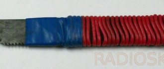
The principle of operation of the tape is as follows. It is divided into segments, each of which contains an LED and a capacitor. They are all connected in parallel, and data is transferred sequentially from one segment to another. Management is carried out by a controller in which the operating program is prescribed. You can control the tape through the Arduino platform.
Address tape marking:
- Black PCB / White PCB – substrate colors;
- 1m/5m – length of address tape;
- 30/60/74, etc. – how many LEDs are there per 1 meter of strip;
- IP30, IP65, IP67 – degree of moisture and dust resistance of the tape =.
Addressable LED strips are used to assemble full-fledged modules, in the construction of lamps with soft lights control, for decorative lighting, and in the construction of diode screens for street advertising.
- Ws2812b
Video instructions and videos
Training video on the HomeMade channel:
Video on creating a ticker based on the ws2112 tape
Connection
Final connection diagram
Let's start with the CAN decoder. Before starting to work with it, following the advice of other users, I immediately soldered the quartz resonator from 8 MHz to 16 MHz . MCP2515 board has two outputs towards the bus: CAN High and CAN Low . We will work with the SWCAN , which is single-wire in nature. This means we connect CAN High to the bus, CAN Low to ground. There are already options here:
- Take SWCAN from the diagnostic block, pin No. 5. Throw some earth there;
- Take SWCAN from the connector for the radio, in it it is numbered No. 14, and ground No. 38:
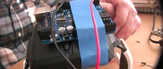
The other side of the MCP2515 is connected to our microcontroller - Arduino UNO . We do this as shown in the diagram:
- INT => D2;
- SCK => D13;
- SI - D11;
- SO - D12;
- CS - D10;
- GND - GND;
- VCC - 5V.
The MP3 player is controlled via the serial port via the RX and TX . In fact, RX is not used, the control is one-way. In the case of Arduino, you can use either a physical interface located on the D0 (RX) and D1 (TX) pins of the Arduino, or use the SoftwareSerial to raise the software interface on any digital pin. I chose the second option and used pin D6 . When I first connected, I encountered interference on the speaker; the solution turned out to be to connect the TX pin through a 1kOhm resistor. Connect the player like this:
- VCC - 5V;
- GND - GND;
- TX - D6;
- SPK_1 and SPK_2 - to the speaker.
This concludes the connection and we move on to the theory about the SWCAN bus.